-

Win a Free Custom Engraved Brass Coin!!!
As a way to introduce our brass coins to the community, we will raffle off a free coin during the month of August. Follow link ABOVE for instructions for entering.
-

PRE-ORDER SHIPS IN SCALE TODAY!
The beloved Ships in Scale Magazine is back and charting a new course for 2026!
Discover new skills, new techniques, and new inspirations in every issue.
NOTE THAT OUR FIRST ISSUE WILL BE JAN/FEB 2026
- Home
- Forums
- Ships of Scale Group Builds and Projects
- Modelship Dockyard PoF HMS Enterprize 1774 - 1/48
You are using an out of date browser. It may not display this or other websites correctly.
You should upgrade or use an alternative browser.
You should upgrade or use an alternative browser.
There is still plenty of room, Russ.I'm a little late to the party, but I hope there's room at the bar. Should be a fun build!
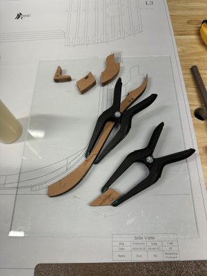
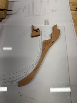
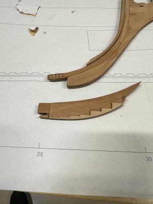
I'm currently in the process of removing the char from the pieces for the cutwater and then will glue them together.
A picture will follow.
Today I'll be working on the rabbet on the cutwater and probably start the keel build. 
Hi Jeff. Found the new Group Build and your build-log. Set my chair and follow it with great interest.
Regards, Peter
Regards, Peter
welcome aboard !Hi Jeff. Found the new Group Build and your build-log. Set my chair and follow it with great interest.
Regards, Peter
Hope you enjoy a bumpy ride.
Good morning. So far all looks mighty fine. That rabbet line is so cool. It will still be a difficult job to get the rabbet sized and cut/scrapped in but what a pleasure. Enjoy. Cheers Grant
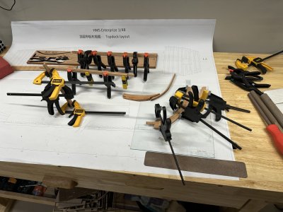
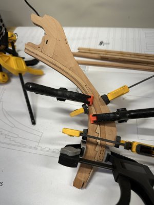
well, i have the deadwood assembled and waiting for the glue to dry to taper it again since I added parts G1-1.
that will be tomorrow. i would post a pic but right now it just looks like a bunch of clamps.
I'll post a pick tomorrow when I can show it without clamps and then tomorrow it will also be attached to the cutwater.
that will be tomorrow. i would post a pic but right now it just looks like a bunch of clamps.
I'll post a pick tomorrow when I can show it without clamps and then tomorrow it will also be attached to the cutwater.
In preparing for the deadwood at the stern, I removed the parts to start cleaning them up for assembly. The parts again fit wonderfully, however, some of the parts in the E3 plate are marked wrong. The instructions say to use 2 of number 13, 2 of 15, 2 of 17 and 2 of 18.
what I found were one marked as 13 but the other marked as 6. One marked as 15, but the other identified as 19. One marked 17 and one unmarked. then I found 2 marked as 18. The parts are pretty easy to identify if you don't get confused by the numbers and search through all the rest of the parts looking for the ones marked with the right numbers
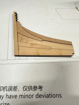
what I found were one marked as 13 but the other marked as 6. One marked as 15, but the other identified as 19. One marked 17 and one unmarked. then I found 2 marked as 18. The parts are pretty easy to identify if you don't get confused by the numbers and search through all the rest of the parts looking for the ones marked with the right numbers

Last edited:
I was a little confused with the term cutwater as I always thought this was just a small piece sometimes on the forward edge of the knee of the head. I did some digging and found that cutwater and knee of the head can be interchangeable terms depending on the source of the definitions. A drawing from Steel, if I remember correctly, is what got me confused. Live and learnIf you look closely at the two pieces that are next to attach to the cutwater, you can see the line for the location of the rabbet.
Allan
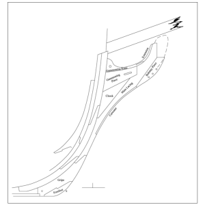
I agree with you. I had not heard the term before I started this kit and I had to do a little research. To be honest, the assembly is more than just the cutwater because it includes the gripe and more. By the way, the kit also points out puting a taper into the knee (tapered toward the fore) and also at the sternpost (tapered toward the keel). I knew you would like that.I was a little confused with the term cutwater as I always thought this was just a small piece sometimes on the forward edge of the knee of the head. I did some digging and found that cutwater and knee of the head can be interchangeable terms depending on the source of the definitions. A drawing from Steel, if I remember correctly, is what got me confused. Live and learnNo matter, this looks to be a very fine kit.
Allan
View attachment 512206
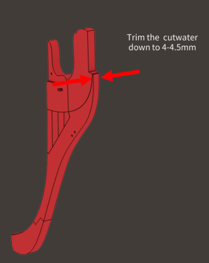
This has to be one of the most researched kits available and they are very receptive to open discussion. I discussed the incorrect number of cabins with them directly and they sent me a very kind thank you and will be correcting this via the instructions.
Allan
Allan
- Joined
- Mar 1, 2022
- Messages
- 685
- Points
- 308

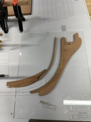
Here are some pics of the cutwater construction.
So far, so good.Still a LONG way to go. It is going together very well. The next step is pretty easy too but the one after that I'm withholding judgement at this stage.
View attachment 511400View attachment 511401
Hi Corsair. May I ask you how thick are transoms? Thanks in advance!In preparing for the deadwood at the stern, I removed the parts to start cleaning them up for assembly. The parts again fit wonderfully, however, some of the parts in the E3 plate are marked wrong. The instructions say to use 2 of number 13, 2 of 15, 2 of 17 and 2 of 18.
what I found were one marked as 13 but the other marked as 6. One marked as 15, but the other identified as 19. One marked 17 and one unmarked. then I found 2 marked as 18. The parts are pretty easy to identify if you don't get confused by the numbers and search through all the rest of the parts looking for the ones marked with the right numbers
View attachment 512173
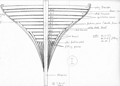
Sure, can you show me what you mean by "transoms"?Hi Corsair. May I ask you how thick are transoms? Thanks in advance!
So, here is a few more pics of the ongoing build. These parts are for both the bow and the stern.
I have also glued the pieces of the keel together but no picture of that since it just looks like a stick.
You can see pieces of the keel at the top of the middle picture, if you really want to see them.
The flat portion of the keel measures about 72 cm (or a little over 28 inches if you prefer).
I'm trying to work out in my head how to make the kerfs in the bottom of the keel and make them look good.


I have also glued the pieces of the keel together but no picture of that since it just looks like a stick.

You can see pieces of the keel at the top of the middle picture, if you really want to see them.
The flat portion of the keel measures about 72 cm (or a little over 28 inches if you prefer).
I'm trying to work out in my head how to make the kerfs in the bottom of the keel and make them look good.


Last edited:
If you are referring to the sided dimension of the transoms at the stern, from the original contract, the five transoms are described as follows:May I ask you how thick are transoms?
WING TRANSOM … The Wing transom to be sided 11½ ins, & moulded at the ends 13 ins, in the Middle 20 ins No Chocks to be admitted on the Aftside, & to be bolted to the Post with 2 bolts of 1¼ inch diameter & to be left 13 ins in the middle for the better room for the bolts.
FILLING TRsm To have two Transoms between the Wing & deck Transoms sided 10 ½ ins & to be left for air between the wing & filling & each other 4 ½ ins & filling & deck planks 5” & to be to be bolted to the post with one bolt of one inch diameter. The Chocks on the Aft side, if any not to exceed 12 ins,
DECK TRsm The Deck Transom to be sided 11 ins & moulded as broad as may be for the better fastening of the plank of the Deck, bolted to the post with one bolt of one inch diameter.
OTHER TRsm To have one whole Transom below the deck Transom free from shakes to be sided 10 ins to lye 3” clear of the deck Transom & both this & the deck Transom kindly grown as not to require the Chocks of the Breech to be too large.
Hope this helps.
Allan
- Joined
- Mar 1, 2022
- Messages
- 685
- Points
- 308

Thanks Allan! Most useful and appreciated. Regards, AlbertoIf you are referring to the sided dimension of the transoms at the stern, from the original contract, the five transoms are described as follows:
WING TRANSOM … The Wing transom to be sided 11½ ins, & moulded at the ends 13 ins, in the Middle 20 ins No Chocks to be admitted on the Aftside, & to be bolted to the Post with 2 bolts of 1¼ inch diameter & to be left 13 ins in the middle for the better room for the bolts.
FILLING TRsm To have two Transoms between the Wing & deck Transoms sided 10 ½ ins & to be left for air between the wing & filling & each other 4 ½ ins & filling & deck planks 5” & to be to be bolted to the post with one bolt of one inch diameter. The Chocks on the Aft side, if any not to exceed 12 ins,
DECK TRsm The Deck Transom to be sided 11 ins & moulded as broad as may be for the better fastening of the plank of the Deck, bolted to the post with one bolt of one inch diameter.
OTHER TRsm To have one whole Transom below the deck Transom free from shakes to be sided 10 ins to lye 3” clear of the deck Transom & both this & the deck Transom kindly grown as not to require the Chocks of the Breech to be too large.
Hope this helps.
Allan


