Danish Bomb Vessel 1771, "Den Gloende", POB, 1:48

Don, I have not heard anything from Joseph since he last posted here. He had asked me if I would send him my drawing so he could do a 3d and I said sure. It hasn't really effected my plan much.

All, I did a little work last night but not much. My strategy to not get stuck with builders block where you don't get anything done is to do something every day. Even if I don't feel like it. On days when I don't have much time I still do something. A lot of the time when I don't really feel like working on it I get the bug once I get started.

So last night I just cut and glued the supports for the aft mortar bed, and marked the gun port and strake locations on the last 5 bulkheads.

IMG_4253%20%281280x992%29-XL.jpg


Then today before I left for work I trimmed the paper off the transom beams. Not much but even a little progress each day adds up.

IMG_4254%20%28593x800%29-XL.jpg


I almost didn't get this posted because I went through the first 24 paes of Zoly's Ontario build.
 
Got some work done over the weekend. Doesn't look like much partly because I cut out quite a few parts for later like upper braces for the stern galley etc that I didn't take photos of. The weather was really nice so I worked outside for most of the day which should speed some of the future steps along.

I scribed the last 5 bulkheads by taking a dial caliper and marking a line down the sides of the frames. The lines are all short from where they need to be finished I just wanted to trim them down to reduce the sanding after they are installed.
now005%20%281280x1274%29-XL.jpg


Here's the bow after sanding and installing.
now003%20%281280x871%29-L.jpg

And the aft end. The red lines are here the transom beams attach.
now002%20%281280x798%29-L.jpg


I also used a sanding drum in the Dremel tool to shape the transom beams.

now001%20%281280x759%29-L.jpg


My next step is to place spacers between the bulkheads at the outside edge so everything will be straight.
 
On Saturday I had some time to work on the ship. I wanted to cut a couple thin strips to use to basically mark the side of the ship to make sure the gun port alignment would look good. So I got out my Byrnes saw. And next thing you know I was totally out of control. An hour and a half later I had the following. I cut 8 Cherry planks for the whales, a .25" x .25" cherry piece for the keel, two rabbet strips, 4 thin boxwood strips for marking the gun port alignment etc. and about 40 3/64" Alaskan Cedar planks. I also cut some parts for the stern on the scroll saw. Here it is all piled on and around the model.

den008-X2.jpg


I didn't take any photos of this but, the next thing I did was take a 1/8" x 1/4" strip to square up the backbone. I measured the distance between the bulkhead at the center of the ship along the backbone and then cut two equal length pieces and glued one on each side. I didn't take any photos before but there was an easily visible curve along the center of the ship which is gone now.

As a side note I thought I would mention even though I have the Byrnes table saw, I still use my little Proxxon shown below for cutting strips to length, and other light duty one time cut sort of stuff. Largely because I keep a fine tooth blade on it for really clean cuts, and a 36 tooth Carbide on the Byrnes.

den003-L.jpg


The next thing I did was glue the stern timbers on. Here is really the first design error I found since I started building this. The stern timbers extend past the back of the backbone because I didn't take into account the angle on the stern post in my design. Not a big deal just need to grind it down but thought I'd show it to everyone.

den001-XL.jpg


I also used my Ships of Scale clamps to add the cheeks on the front. I'm calling the clamps that because I saw them here on this web site. They're great clamps and reasonably priced from Menards.

den002-L.jpg


Yesterday I planked the mortar beds with some very thin walnut planking from the scrap bin, and glued them in. I did not do any type of seams on the planking because this will be under the mortar in the bottom of an octagonal hole so probably 95 covered. You can also see the side braces I added the day before to straighten the keel.

den007-L.jpg


And the larger View

den010-XL.jpg


I glued a ledge on the back of one of the bulkheads. It is curved to match the crown of the deck, so the subdeck piece will be glued down to match the arc of the bulkheads.

den006-L.jpg


And finally roughed in the stern timbers to match the bulkhead and stern post, and glued on the rabbet strips. When I glued the rabbet strip on I realized the rabbet was just slightly narrower than the backbone. Don't think this will cause any problems, but the reason is the plywood I used is .208" thick and the keel will be .25" thick.

den004-XL.jpg


If I were building a kit, I would be very confident that the next step I should work on is filling in the bow and stern blocks and then fairing the hull, before I put anything on it that I might eventually break off. However; with this not being a kit, I think I'm going to approach it a little differently. The one thing I haven't felt confident with on this whole process is the construction of the upper stern area around the cabins. So I'm going to work on framing the stern to the point that I feel confident this little project is going to be successful before I spend hours sanding the hull smooth. I'm also thinking I may frame the gun ports before I do any fairing, to strengthen the ears on the bulkheads.

So here's where I'm at now. I have cut out the formers for the cabin area etc, as well as cut out the wing transom. I cut the wing transom in from two 1/8" pieces of basswood and the soaked them in water for about an hour and clamped them to a piece of wood that was cut to match the camber of the rest of the deck. The wing is on the workbench held by the clamp.

Hoping to get some of this put together tonight, here's how it sits now.

den009-XL.jpg
 
I took the plunge last night and just started putting the upper stern together. I think my design might be a bit over complicated but I'm now confident it will work. It's ugly but everything will be covered up, so cosmetically it doesn't really matter. Though I must confess I considered taking some cell phone photos that don't show every minute rough detail.

den021-XL.jpg


Here's another view

den022-X3.jpg


Here's the overall as it sits now.

den023-XL.jpg


Next up I'll go ahead and add the bow blocking and get the hull faired and cleaned up. Then I'll frame the gun ports.
 
Some time in the middle of last week I cut the wing transom off with a jewelers saw. I meticulously checked and re-checked the rear structure as I built it until I got to the last piece, which was the wing transom. I the just glued it on by eye. You can see in the second to last photo in last weeks post that it was lower on the left side. That is not an optical illusion. So I got that on straight last week.

Over the weekend, I got some more work done. I thought about going right to fairing the hull, but I had already broke off and had to repair three ears on bulkheads, so I switched gears and started working on the rails to strengthen the ears. I didn't take a photo till I had gotten to the rear railing and finished for the night. I used basswood on the bottom so I could shape it and walnut on the top rail because it was what I had a scrap of, that was the right size. Here it is clamped up to dry.

den030-XL.jpg

Here's the full length in the morning.
den031-XL.jpg

Saturday I spent quite a bit of time getting the foam on the front and rear. My initial plan was to fill the next space forward from the rear, and the next space back from the front. However, my foam cutter wouldn't work because the transformer was dead. So I had to do it the old fashioned messy way with a knife and a file. The planks lay nice all around the nose and rear when I was testing so I think I'll just skip the extra blocking.
Here's the front
den032-X2.jpg


And the little area on the lower stern.

den033-XL.jpg


I also cut and fit in a repair section on the bottom of the bulkhead. The tip of this bulkhead was cut in a bad spot in the plywood that pretty much crumbled when I was gluing it on. I still need to rework the fairing in this. I forgot about it yesterday.
den034-X2.jpg


After getting these in place I started sanding and sanded and sanded, you get the picture. I also attached the stern post which is made from cherry.

den036-XL.jpg


Beginning yesterday about noon I started by adding the posts on the sides of the gun ports. I didn't take a photo till I was starting on the sweep ports. I did the sweep ports by gluing a channel as seen below.
den037-XL.jpg


I then took the C channel and cut it at an angle with the tilting table on my Byrnes saw. I had to mention that because it's the first time I found a use for the tilting table. Then glued them on and once again sanded and sanded and sanded till the sides of the rails were flat.
den038-XL.jpg

Here's the front view now
den039-X2.jpg

And a view from the back
den041-XL.jpg


I'm hoping to get some time tonight and get the blocking for the masts in. I keep worrying about forgetting it, but still haven't done it. Then I'd like to get the front railing structure framed in.
 
Minor update, last night I managed to place the blocking below the deck for the Main an Mizzen Masts. Cut the dowels long just to get the location right they're obviously way too tall.

IMG_4269%20%281280x1173%29-X2.jpg


And also glued in the rear sub deck. This will hold the front wall of the cabin on the stern, as well as locating the aft pumps.

IMG_4270%20%28796x1024%29-X2.jpg
 
I did a little more work a week ago but never got the photos posted. I kind of got sidetracked by helping a friend build a guitar, and a Black Pearl Kit. At any rate here's a minor update on this ship. I cut out, cleaned up, and sanded the stem and then attached the stem and keel to the ship.

den051-XL.jpg


Here's a closeup of the stem. The stem and keel are made of cherry, I've been pretty much just using whatever I have laying around as far as woof type is concerned, it should be interesting too see how this looks when it's planked etc. I cut the slot on my mill with a downcutting mill for wood and plastic that Donnie pointed me to. It worked awesome with no chipping etc.

den052-X3.jpg
 
Very good looking basis - looks very stiff
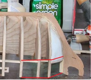
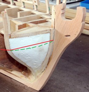
I have only a feeling, so maybe you check the form of the bow, especially the filling piece. But it can be also because of the perspective of the camera.
Especially bomb vessels were not fast ships, so their bow was very round (green line)
Maybe you check the lines of the vessel and compare with your bow, not that you get a buckle in the planking later on
den051-XL.jpg den052-X3.jpg
 
Uwe,

I think that is mostly because of the camera angle the sharp curve begins clear back at the next frame to the rear. I actually did some work on it over the weekend just hadn't got it posted.

I had to add some supports at the rear to form the gallery and have something to attach the whael too. I also painted the gun ports and where the two windows will be at the stern area. Here's the new rear pieces and painted ports.

IMG_4276%20%281280x810%29-XL.jpg


IMG_4281%20%281280x949%29-L.jpg


Here's the bow with the upper whales attached. You can see here the bend actually starts two frames back. It's a smooth bend without any kinks. The front is really wide and fat, though not flat I'll get a photo from the top tonight. You can really see why these were known for having poor sailing qualities.

IMG_4278%20%281245x1280%29-X2.jpg


Here's a photo down the side. The wales follow the deck line back to about the rearmost gun port and then sweep up, this is shown on the sheer plan. I spent a lot of time looking at this location being as it will set the lay of the rest of the planking.

IMG_4279%20%281280x535%29-XL.jpg
 
Here's a photo from a different perspective so folks can see the foam isn't nearly as flat as it looks in most of the photos. The clamp I was using did pull the plank in a little at the first bulkhead. It's not noticeable with the bare eye, I'll see if it shows up when I put the plank below it on.

IMG_4283%20%281280x843%29-L.jpg


Another odd issue with scratch building is the lack of instructions or guidance. Just like with rigging there are a lot of different orders you can use to build something. One build I have says to put in the false deck and plank the deck before the sides and my other references shows planking the sides at this point. I'd be interested in peoples thoughts on which way to go from here, I can see advantages to both. I'm even considering planking the bulwarks first so I don't break the rail while working on the bottom.
 
I've been away from the forum for a while. done a lot of other projects and I've been working on a ZHL Black Pearl all Scenario at the same time. So last night I finally decided to get back to work on my scratch build. Scratch building is rewarding but also time consuming. This seems odd to me but according to the cross sections on the original plans there a 3 of these thicker planks ("whales" I think?) running down the sides. I decided to start by putting them on where they are curved along the bow. I cut these from Cherry on my table saw so they are a little rough.

DG100-XL.jpg


Took a couple better photos after it dried. After a little sanding I am still having this dream of possibly pulling off a single layer of planking, this is my first scratch build a ship and also my first attempt at not double planking.

DG101-XL.jpg


Here's a frontal view.

DG102-XL.jpg


My plan at this point is to switch to planking up the Gunwales to the top. The main reason is I've already broke off and had to repair 4 or 5 of the ears sticking up above the deck. I'd like to get that reinforced so I can lay it upside down to work on the lower hull. Tonight I also need to take a closer look at the fantail and how everything will be tied together back there.
 
Quick update from last night. I decided to plank the lower stern. I've been concerned for quite a while about how the hull planking will be curved on the rear area. One big enemy of completing ship models is when you get to something you're not sure how to accomplish, so you just quit. I learned long ago better to do it wrong than do nothing. At the very least you'll learn you need to do it differently.

So last night I just plowed forward and attached the planking on the rear. As a matter of practicality the lower hull planks need something solid to attach to where they terminate below these horizontal stern planks. With my current construction I decided I would either need to attach to the upper transom beam, or I would need to add a piece between the wing transom and the top transom beam. Being as the original plans don't show a beam between the two I decided the planking must have been attached to the upper transom beam. Here's a photo reposted from above, the wing transom is the arched one and the next down is where I believe the lower planks were attached.

IMG_4281%20%281280x949%29-L.jpg


I was concerned this wasn't right because the 3 thick wale planks clearly shown on all of the cross section plans, have to terminate in this area. The one you can see already attached in the photo below being the top whale plank.

IMG_4461%20%281280x960%29-XL.jpg


I went back and took a look at some of the photos I had downloaded when I was trying to find references for Danish ships and several of them are in this same configuration with a wide whale band having the lower planks beginning the wrap under the stern. So to be honest I started out just trying to make it work, but think I have actually got it substantially right.

I don't know if I'll have time tonight, but I hope to get the other whale planks on tonight or tomorrow.
 
I forgot to post this photo. Back in January, or there about, I ordered some cannon and carriages from from @Dave Stevens (Lumberyard) . I got them months ago and never posted, but wanted to mention they look great. The standard loadout lists 4-12 pound and 6-4 pound canon and there are 8 mounts for swivel guns. The plans list a couple alternate loadouts that are really confusing. The bomb ships transited without the Mortars, the mortars were placed on tender ships that carried the mortars and more ammunition. When the mortars were loaded aboard; they most likely removed some of the cannon that would have been near the mortal locations when the mortars were not on board. So now I just have to turn the mortar barrels on the lathe and make them from scratch.

i-g5KKx45-L.jpg
 
So I got some more planking done this weekend. I need to go back through some planking tutorials before I do the bottom. Probably should have done that for the top. In order to get the planks to sit along the bulwarks where they come around the bow I had to do a compound bend. So I thought I'd show real quick how I bend planks the wrong direction. Like the lower one below.

dg113-XL.jpg


I just place two c clamps on my steel workbench and use a styling (curling) Iron, while bending the plank. The styling iron doesn't have a clamp doohickey on it. Not a big deal but some people looking at this thread may not have seen this done.

dg114-L.jpg


Then the plank will go around the bow and lean in toward the center of the ship at the same time.

dg117-L.jpg


I managed to get the lower stern planked to my satisfaction. I made a mistake on my first try, hence the putty on the port side, but managed to also get the planks to bend up around the stern. This was the one thing I was really concerned I wouldn't be able to make work. At this point I'm confident I can turn this into a descent finished Model. All of my previous models had a flat section on the stern so the planks didn't have to make this radical bend.

dg116-XL.jpg


And here's some overall photos of the progress this weekend.

dg110-XL.jpg


dg111-XL.jpg


dg112-XL.jpg
 
Back
Top