Fokker Spin III, scale 1:48, scratch build

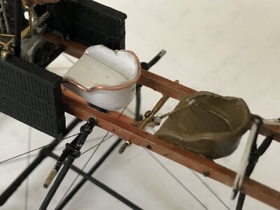
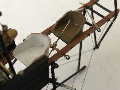
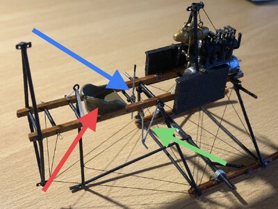
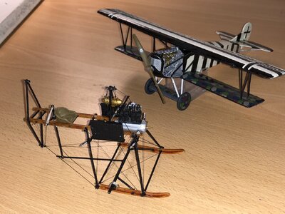
The pilot’s seat saw completion. It’s build from a formed 0,5mm brass wire and some sturdy paper, which I used for mast hoops on another build. Quite an undertaking, since the brass wire has to be formed by hand, which is not exactly my forte. Combining the brass with the paper worked quite well, but it took forever before I had something acceptable.

I also revised the aft shock absorber; the bungee cord lay close to horizontal, whereas it should have an angle of about 60 degrees with horizontal.

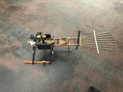
Below the Spin With the pilot seat and revised aft shock absorber. In the background the Rhodens’ Fokker D.VII. (Both in 1:48)
IMG_1952.jpeg
 
Today I fabricated the passenger seat, which came out better than the pilots’ seat, currently no plans to redo the latter.
Seat dimensions, approx 10x10

I also worked on the control column. The version in the picture will face a redo, but it gives an idea towards what I’m working to. The column will be rotating in two axes; X-and Y-axis, when Z is vertical.

IMG_1953.jpeg

IMG_1954.jpeg
 
Today I fabricated the passenger seat, which came out better than the pilots’ seat, currently no plans to redo the latter.
Seat dimensions, approx 10x10

I also worked on the control column. The version in the picture will face a redo, but it gives an idea towards what I’m working to. The column will be rotating in two axes; X-and Y-axis, when Z is vertical.

View attachment 451349

View attachment 451419
That’s looking very nice, Johan. The pilots’ seat is more used, especially on all the test flights. You have to pamper a passenger, he/she got the better seat. So the outcome is realistic.
My reference is the serafil wire ……… then that are tiny parts!
Regards, Peter
 
Today I fabricated the passenger seat, which came out better than the pilots’ seat, currently no plans to redo the latter.
Seat dimensions, approx 10x10

I also worked on the control column. The version in the picture will face a redo, but it gives an idea towards what I’m working to. The column will be rotating in two axes; X-and Y-axis, when Z is vertical.

View attachment 451349

View attachment 451419
Good morning Johan. Wow…those seats are amazing- I don’t know how you did it with wire and paper, however you owned it. Cheers Grant
 
That’s looking very nice, Johan. The pilots’ seat is more used, especially on all the test flights. You have to pamper a passenger, he/she got the better seat. So the outcome is realistic.
My reference is the serafil wire ……… then that are tiny parts!
Regards, Peter
Good morning Johan. Wow…those seats are amazing- I don’t know how you did it with wire and paper, however you owned it. Cheers Grant
Wonderful work, Johan very nicely done seats, good idea with the wire and paper.
Nice tiny details and a passenger seat must look good, there must be a reason to get into this plane as passenger, the seat will do it.
Thanks for your compliments, gentlemen.

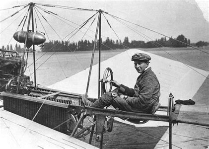
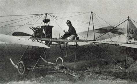
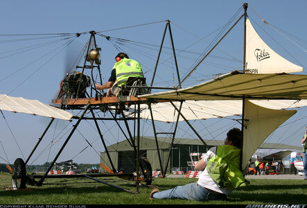
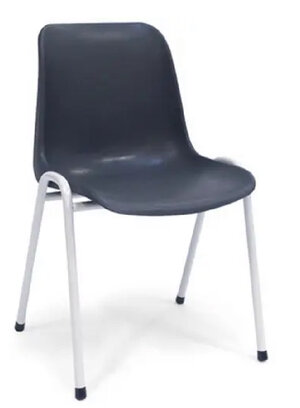
Those seats are something else. There are at least three possible seat configurations and maybe even more, but that's unconfirmed. The initial seat consisted of a frame in a curved U-shape with wooden planks across. The other seat was a kind of wicker seat (possibly), which probably was a bit more comfortable than the initial seat. The third option stems from the (restored) 1936 replica and suggests the seat of a chair, commonly seen in canteens in the Netherlands.

The original seat of the Spin ( with a young Anthony Fokker at the controls):
IMG_0497.jpeg

The “wicker” seat of the Spin III:
IMG_0498.jpeg

And the borrowed canteen chair of the replica:
IMG_0499.jpeg

Commonly used canteen chair:
IMG_0496.jpeg
 
Last edited:
The build has now shifted towards the fabrication of the elevator and rudders.
I made an elevator frame from dia 0,5mm longerons, a tube dia 1,0mm for a front spar and a 0,3mm thick rear spar. The trailing edge was made using the trusted Serafil. Initially I considered soldering the frame assembly, but the heat transfer rate of brass is way too much, so I opted for CA glue. This is where I’m at:
IMG_1969.jpeg
 
My eyes are always drawn to the gold gas tank and its apparent suspension off the upper frame. Curious way of attachment, seems like the tank could swing knocking around on the frame? You have a clever assortment of materials making up the elevator. It's all looking great Johan.
My guess is the fuel tank was made from copper. The suspension is a bit of a mystery, the two cables from the top to the fuel tank are a given. There is pictorial evidence suggesting that there are four cables frome the two bands around the tank to the struts. That is, the pictures from the replica shows these cables. The drawings I have are so obscure that I can't distinguish one or the other. Complicating matters is the lack of space around the tank, preventing me from running lines from the tank to the struts.
 
The build has now shifted towards the fabrication of the elevator and rudders.
I made an elevator frame from dia 0,5mm longerons, a tube dia 1,0mm for a front spar and a 0,3mm thick rear spar. The trailing edge was made using the trusted Serafil. Initially I considered soldering the frame assembly, but the heat transfer rate of brass is way too much, so I opted for CA glue. This is where I’m at:
View attachment 451674
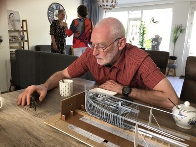
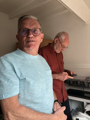
Henk and I where privileged to see this morning the results till now of the build of Johan’s Spin. And it’s looking much more impressive then what you see on the pictures. And I can tell now: there are already a lot of tiny and fragile parts. But the serafil wires holds the structure very well together. And ……. The suspension behind the aft seat works :D …. The controle column works :D …..
Very nice to see, Johan.
Regards, Peter
 
Hey Johan,

Nice that we spoke again, it was very pleasant and informative as usual.

Yvon also thought it was a nice day and enjoyed having you there.

Very nice to see your progress.

Live gives a better impression of your construction.

I find what you show very impressive,

Regards
De Haasjes
 
Henk and I where privileged to see this morning the results till now of the build of Johan’s Spin. And it’s looking much more impressive then what you see on the pictures. And I can tell now: there are already a lot of tiny and fragile parts. But the serafil wires holds the structure very well together. And ……. The suspension behind the aft seat works :D …. The controle column works :D …..
Very nice to see, Johan.
Regards, Peter

Hey Johan,

Nice that we spoke again, it was very pleasant and informative as usual.

Yvon also thought it was a nice day and enjoyed having you there.

Very nice to see your progress.

Live gives a better impression of your construction.

I find what you show very impressive,

Regards
De Haasjes

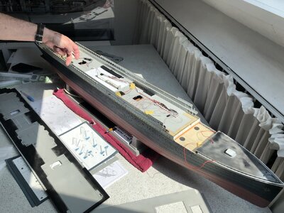
Dear Peter and Henk, for sure we did have a wonderful meeting where we got reaquinted with one another’s work.
From the one of a kind build of the Balder (Peter) to Henk’s minutieus work on his Titanic to the tiny Spider, currently my build.
A heartfelt thanks to Henk and his Admiral for their hospitality.

IMG_1971.jpeg

IMG_1972.jpeg

IMG_1973.jpeg
 
The build has now shifted towards the fabrication of the elevator and rudders.
I made an elevator frame from dia 0,5mm longerons, a tube dia 1,0mm for a front spar and a 0,3mm thick rear spar. The trailing edge was made using the trusted Serafil. Initially I considered soldering the frame assembly, but the heat transfer rate of brass is way too much, so I opted for CA glue. This is where I’m at:
View attachment 451674
Good morning Johan. This is incredible and detail on such a small “spider” is mind blowing. I’m impressed. Cheers Grant
 
Back
Top