I love those photos very much! Of course, I saw the models in the build logs, but when our forum members meet each other - this is golden! I am happy for you Johan, Peter, and Henk!!
- Home
- Forums
- Ships of Scale Build Logs
- Super Detailing Static Models / Other Genres
- Historical Trailways, Guns, Aircraft, and Cars
You are using an out of date browser. It may not display this or other websites correctly.
You should upgrade or use an alternative browser.
You should upgrade or use an alternative browser.
- Joined
- Sep 3, 2021
- Messages
- 4,440
- Points
- 688

This week saw a lot of work on the empennage and a start on the wing.
The covering of the horizontal tail plane was subject to some deliberations. My initial plan was to use Amati cloth, pre-treated with diluted woodglue and stain, followed by bonding to the framework. During our meeting at Henk's place the other week Peter suggested to use tissue paper instead. Initially I was rather anxious of this idea (which was used by Peter on his Bluenose model to make sails), but after dragging my feet for a couple of days, I decided to give it a shot.
I cut and split some tissue, draped it over the horizontal tail and applied the diluted woodglue mix. After having applied two layers of the mix, I painted the tissue twice with Vallejo paint. This gave a rather nice result, so I decided to make the upper- and lower rudder, lo and behold, split rudders are nothing new, and gave those a similar treatment.
The rudders pivot on an axle, which in turn is supported on three points. One of those points is on the rear spar of the horizontal, the other two are above and below the rudders supported by spars coming from the aft fuselage. That whole construction needs to be supported by numerous cables, to provide the necessary stability.
The rudders themselves were made from a tube, dia 1mm and provides the hinge line, also attached to the tube is a cantilever for rudder control, one single rib and two threads on the upper and lower edge of the rudder. That framework again is covered by tissue, folded over the hinge axle, resulting in a double layered skin. Further treatment the same as the horizontal stabilizer.
The lower rudder seems to be a little bit different from the upper rudder. The only reason I came up with to justify this is to have more pitch-up control.
As I mentioned, construction on the wing als started. The wing is of a two spar, multi-rib lay-out, a configuration still in use today, although... Each wing half has four ribs spread out over the span of the wing,which at a later stage will have cables attached to hold up the wing. The other ribs have a very rudimentary aerodynamic shape and will later be covered with one layer of tissue. The four main ribs are soldered to the spars, the others ribs will be bonded with CA adhesive; the rib pitch is too small to solder the ribs.
The two wing halves with the four main ribs are complete, now the process of bonding the form ribs is in progress.
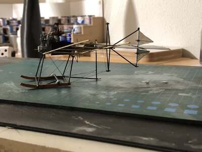
Below a picture, showing the current status. The empennage is 80% complete, with flight control wiring and stability wiring still to be added. Also in this picture the two wing halves, with the start of the installation of the form ribs.
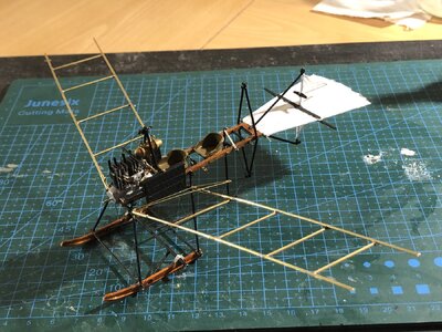
A better view of the upper- and lower rudders.
The covering of the horizontal tail plane was subject to some deliberations. My initial plan was to use Amati cloth, pre-treated with diluted woodglue and stain, followed by bonding to the framework. During our meeting at Henk's place the other week Peter suggested to use tissue paper instead. Initially I was rather anxious of this idea (which was used by Peter on his Bluenose model to make sails), but after dragging my feet for a couple of days, I decided to give it a shot.
I cut and split some tissue, draped it over the horizontal tail and applied the diluted woodglue mix. After having applied two layers of the mix, I painted the tissue twice with Vallejo paint. This gave a rather nice result, so I decided to make the upper- and lower rudder, lo and behold, split rudders are nothing new, and gave those a similar treatment.
The rudders pivot on an axle, which in turn is supported on three points. One of those points is on the rear spar of the horizontal, the other two are above and below the rudders supported by spars coming from the aft fuselage. That whole construction needs to be supported by numerous cables, to provide the necessary stability.
The rudders themselves were made from a tube, dia 1mm and provides the hinge line, also attached to the tube is a cantilever for rudder control, one single rib and two threads on the upper and lower edge of the rudder. That framework again is covered by tissue, folded over the hinge axle, resulting in a double layered skin. Further treatment the same as the horizontal stabilizer.
The lower rudder seems to be a little bit different from the upper rudder. The only reason I came up with to justify this is to have more pitch-up control.
As I mentioned, construction on the wing als started. The wing is of a two spar, multi-rib lay-out, a configuration still in use today, although... Each wing half has four ribs spread out over the span of the wing,which at a later stage will have cables attached to hold up the wing. The other ribs have a very rudimentary aerodynamic shape and will later be covered with one layer of tissue. The four main ribs are soldered to the spars, the others ribs will be bonded with CA adhesive; the rib pitch is too small to solder the ribs.
The two wing halves with the four main ribs are complete, now the process of bonding the form ribs is in progress.
Below a picture, showing the current status. The empennage is 80% complete, with flight control wiring and stability wiring still to be added. Also in this picture the two wing halves, with the start of the installation of the form ribs.

A better view of the upper- and lower rudders.

Very nice Johan!
That’s looking very nice, Johan. I am glad you give the tissue-option a try.This week saw a lot of work on the empennage and a start on the wing.
The covering of the horizontal tail plane was subject to some deliberations. My initial plan was to use Amati cloth, pre-treated with diluted woodglue and stain, followed by bonding to the framework. During our meeting at Henk's place the other week Peter suggested to use tissue paper instead. Initially I was rather anxious of this idea (which was used by Peter on his Bluenose model to make sails), but after dragging my feet for a couple of days, I decided to give it a shot.
I cut and split some tissue, draped it over the horizontal tail and applied the diluted woodglue mix. After having applied two layers of the mix, I painted the tissue twice with Vallejo paint. This gave a rather nice result, so I decided to make the upper- and lower rudder, lo and behold, split rudders are nothing new, and gave those a similar treatment.
The rudders pivot on an axle, which in turn is supported on three points. One of those points is on the rear spar of the horizontal, the other two are above and below the rudders supported by spars coming from the aft fuselage. That whole construction needs to be supported by numerous cables, to provide the necessary stability.
The rudders themselves were made from a tube, dia 1mm and provides the hinge line, also attached to the tube is a cantilever for rudder control, one single rib and two threads on the upper and lower edge of the rudder. That framework again is covered by tissue, folded over the hinge axle, resulting in a double layered skin. Further treatment the same as the horizontal stabilizer.
The lower rudder seems to be a little bit different from the upper rudder. The only reason I came up with to justify this is to have more pitch-up control.
As I mentioned, construction on the wing als started. The wing is of a two spar, multi-rib lay-out, a configuration still in use today, although... Each wing half has four ribs spread out over the span of the wing,which at a later stage will have cables attached to hold up the wing. The other ribs have a very rudimentary aerodynamic shape and will later be covered with one layer of tissue. The four main ribs are soldered to the spars, the others ribs will be bonded with CA adhesive; the rib pitch is too small to solder the ribs.
The two wing halves with the four main ribs are complete, now the process of bonding the form ribs is in progress.
Below a picture, showing the current status. The empennage is 80% complete, with flight control wiring and stability wiring still to be added. Also in this picture the two wing halves, with the start of the installation of the form ribs.
View attachment 453378
A better view of the upper- and lower rudders.
View attachment 453380
Regards, Peter
It looks like the frame was designed using actual birds. The tail section especially looks close to that of some fan-shapes you can see in some birds such as a bow tailed grackle.
- Joined
- Sep 3, 2021
- Messages
- 4,440
- Points
- 688

The Dutch Flying Spider...The tiny little spider got wings.
Thanks Paul.Very nice Johan!
The tissue is a nightmare to work worth, but it definitely pays dividends.That’s looking very nice, Johan. I am glad you give the tissue-option a try.
Regards, Peter
Very much so, Dan. I think that in those early days of aviation a lot of features were copied from our (feathered) avians.It looks like the frame was designed using actual birds. The tail section especially looks close to that of some fan-shapes you can see in some birds such as a bow tailed grackle.
Still a lot of innovation went into those strange looking contraptions. One of those being warping of the wing and in this case the tail for pitch and roll control; one of the ongoing R&D programs when I left the company was a study to introduce warping control surfaces to modern day aircraft. Fokker also incorporated a swept back wing into his Spin design and a rather high angle of incidence. This led to a very stable design and is said to alleviate the need for roll control, so no ailerons.
Thanks, ShotaJohan, I like your project, it's unique!
Baai Baai mooi- Johan. The guys who flew these little planes has some serious courage- they do look like they will just fold in half. Brilliant detail Johan. Cheers GrantThis week saw a lot of work on the empennage and a start on the wing.
The covering of the horizontal tail plane was subject to some deliberations. My initial plan was to use Amati cloth, pre-treated with diluted woodglue and stain, followed by bonding to the framework. During our meeting at Henk's place the other week Peter suggested to use tissue paper instead. Initially I was rather anxious of this idea (which was used by Peter on his Bluenose model to make sails), but after dragging my feet for a couple of days, I decided to give it a shot.
I cut and split some tissue, draped it over the horizontal tail and applied the diluted woodglue mix. After having applied two layers of the mix, I painted the tissue twice with Vallejo paint. This gave a rather nice result, so I decided to make the upper- and lower rudder, lo and behold, split rudders are nothing new, and gave those a similar treatment.
The rudders pivot on an axle, which in turn is supported on three points. One of those points is on the rear spar of the horizontal, the other two are above and below the rudders supported by spars coming from the aft fuselage. That whole construction needs to be supported by numerous cables, to provide the necessary stability.
The rudders themselves were made from a tube, dia 1mm and provides the hinge line, also attached to the tube is a cantilever for rudder control, one single rib and two threads on the upper and lower edge of the rudder. That framework again is covered by tissue, folded over the hinge axle, resulting in a double layered skin. Further treatment the same as the horizontal stabilizer.
The lower rudder seems to be a little bit different from the upper rudder. The only reason I came up with to justify this is to have more pitch-up control.
As I mentioned, construction on the wing als started. The wing is of a two spar, multi-rib lay-out, a configuration still in use today, although... Each wing half has four ribs spread out over the span of the wing,which at a later stage will have cables attached to hold up the wing. The other ribs have a very rudimentary aerodynamic shape and will later be covered with one layer of tissue. The four main ribs are soldered to the spars, the others ribs will be bonded with CA adhesive; the rib pitch is too small to solder the ribs.
The two wing halves with the four main ribs are complete, now the process of bonding the form ribs is in progress.
Below a picture, showing the current status. The empennage is 80% complete, with flight control wiring and stability wiring still to be added. Also in this picture the two wing halves, with the start of the installation of the form ribs.
View attachment 453378
A better view of the upper- and lower rudders.
View attachment 453380
- Joined
- Sep 3, 2021
- Messages
- 4,440
- Points
- 688

Thank you so much, Grant.Baai Baai mooi- Johan. The guys who flew these little planes has some serious courage- they do look like they will just fold in half. Brilliant detail Johan. Cheers Grant
It’s amazing how much some well placed brace wires turn the flimsy looking planes into sturdy constructions.
Still, I wouldn’t be able to find the courage to fly a contraption like the Spin…
- Joined
- Sep 3, 2021
- Messages
- 4,440
- Points
- 688

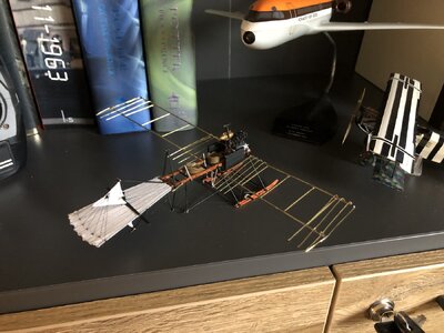
After hours of fiddling with Serafil, the wires for controlling the rudders and the warping horizontal stabilizer, I now finally have functional, by means of the control stick, control surfaces.
The winghalves are also taking shape, although process is slow. I tried two brass wire types, soft and though, but the tough one is hard to form, whereas the softer brass type deforms too easily. In all, to get nice looking wings is one heck of a challenge.
Stick to the right, rudders to the right:
(Status of the wing can also be seen.)
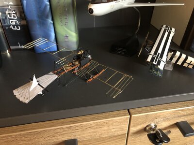
Stick to the left, rudders to the left:
The winghalves are also taking shape, although process is slow. I tried two brass wire types, soft and though, but the tough one is hard to form, whereas the softer brass type deforms too easily. In all, to get nice looking wings is one heck of a challenge.
Stick to the right, rudders to the right:
(Status of the wing can also be seen.)

Stick to the left, rudders to the left:

Last edited:
Just a BIG WOW for your fully functional rudder, Johan. A great detail.After hours of fiddling with Serafil, the wires for controlling the rudders and the warping horizontal stabilizer, I now finally have functional, by means of the control stick, control surfaces.
The winghalves are also taking shape, although process is slow. I tried to brass wire types, soft and though, but the tough one is hard to form, whereas the softer brass type deforms too easily. In all, to get nice looking wings is one heck of a challenge.
Stick to the right, rudders to the right:
(Status of the wing can also be seen.)
View attachment 454102
Stick to the left, rudders to the left:
View attachment 454103
Regards, Peter
- Joined
- Oct 28, 2018
- Messages
- 685
- Points
- 403

Nice work Johan,
I heard you before about fat fingers.
There is little to be seen...
I know how incredibly small this is, so there is a lot of appreciation, there is nothing wrong with your fingers.
Despite the fact that I am on 'follow-up mode', I do not get any notifications via my email, so a late response.
Regards
Henk
- Joined
- Sep 3, 2021
- Messages
- 4,440
- Points
- 688

No worries, Henk, I experience the same with a number of builds I follow. It’s been going on for a while now.Despite the fact that I am on 'follow-up mode', I do not get any notifications via my email, so a late response.
- Joined
- Sep 3, 2021
- Messages
- 4,440
- Points
- 688

Just a BIG WOW for your fully functional rudder, Johan. A great detail.
Regards, Peter
Thanks, gentlemen, it’s appreciated.Nice work Johan,
I heard you before about fat fingers.
There is little to be seen...
I know how incredibly small this is, so there is a lot of appreciation, there is nothing wrong with your fingers.
Despite the fact that I am on 'follow-up mode', I do not get any notifications via my email, so a late response.
Regards
Henk
It’s challenging to get things to work at this scale, but o so satisfying.
Thanks to the challenges, given by some of our fellow builders, this little Spin is turning out to be way better than I anticipated.
Hello Johan,
Incredible work on your rudder operation and horizontal stabilizer. I can’t wait to see how you will develop the wing warping.
Bill
Incredible work on your rudder operation and horizontal stabilizer. I can’t wait to see how you will develop the wing warping.
Bill
- Joined
- Sep 3, 2021
- Messages
- 4,440
- Points
- 688

Thanks, Bill.Hello Johan,
Incredible work on your rudder operation and horizontal stabilizer. I can’t wait to see how you will develop the wing warping.
Bill
Funny you should mention the wing warping. The earliest Spin had directional- and roll control by warping the wings, but no rudders, whereas later models had no control through wing warping, but instead had rudders for directional- and roll control.
Roll stability was obtained by both a large wing dihedral angle (10 degrees) and a swept back wing, also 10 degrees.
As a consequence the Spin was difficult to fly in adverse weather conditions and also when having to take off and land with a cross wind component. In later designs, like the (in)famous Fokker Eindecker, Fokker again used the warped wing design for roll control.
- Joined
- Sep 3, 2021
- Messages
- 4,440
- Points
- 688

The pictures below show the installed brace wires on the empennage of the Spin, with the wires for rudder- and elevator control.
(Did I already mention that those macro pics are killing?)
View from the bottom/right looking up/left:
In the center of the picture is the aft skid, to protect the lower rudder. In the left hand side of the picture the shock absorber can be seen. Its location is just aft of the pilot seat.
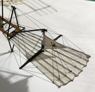
Now looking from left/up to down/right:
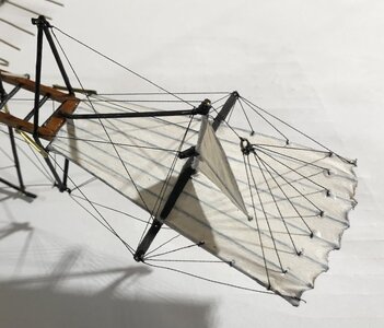
(Did I already mention that those macro pics are killing?)
View from the bottom/right looking up/left:
In the center of the picture is the aft skid, to protect the lower rudder. In the left hand side of the picture the shock absorber can be seen. Its location is just aft of the pilot seat.

Now looking from left/up to down/right:

- Joined
- Sep 3, 2021
- Messages
- 4,440
- Points
- 688

My experience with tweezers has gone up a notch or two…the details you make with your big fingers, wow.


