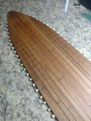
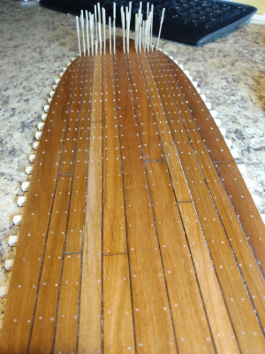
Gunboat Philadelphia 1776 POF, Pseudo Admiralty Style... from Smithsonian Plans

Joined
Apr 12, 2025
Messages
42
Points
48

1776 Gunboat Philadelphia
"Short in life, 'Long' in history!"

A Build Log
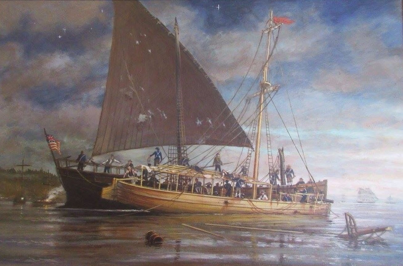
1eb68f6300baaacad39c2c0ef986da76.jpg.2032dbf29ded0bd67a67c617a730bd9f.jpg
Painting: "The sinking of the Gunboat Philadelphia"... by Ernest Haas


In 1776, the British planned to split the American colonies by advancing south from Canada, via Lake Champlain and the Hudson River. Colonel Benedict Arnold was tasked with delaying that imminent British invasion and recognized the strategic importance of Lake Champlain. Arnold took command of a small flotilla of curious vessels in order to effectively impede that British advancement. Arnold's fleet consisted of 15 vessels, including 8 gunboats. Seeing how this is a 'gunboat' build, I'll exclude mention of the 'other' vessels. The eight gunboats built were named Spitfire, Philadelphia, Congress, Washington, New York, Jersey, Connecticut and Lee. These gunboats were all hastily constructed late during the summer of 1776 in Skenesborough, New York... now known as Whitehall, in a location at the southern end of Lake Champlain.

Due to extreme urgency, these gunboats were likely built from green wood. There's also a good chance that no true shipwrights were actively involved in the actual construction of these vessels, evidence being via the unusual manner in which these boats were built. The construction of these gunboats was probably performed by local 'carpenters' who had very little experience as shipwrights, but actually knew quite a lot about building disposable, cheap and effective 'flat bottomed river batteaux's' that were used extensively in the fur trade as well as general cargo transport along the rivers located in that region. This is just logical speculation, of course. Very few records exist. It's difficult to really know for sure.

On October 11, 1776, Arnold positioned his fleet in a narrow part of Lake Champlain, near Valcour Island. This positioning was strategic, forcing the British to sail into a confined space where their larger fleet's numerical superiority would be rendered much less effective. The battle began when the British fleet, under General Guy Carleton and commanded by Captain Thomas Pringle encountered Arnold’s fleet. Despite being outnumbered and outgunned, Arnold's forces fought tenaciously. After a day of intense fighting, Arnold's fleet suffered very heavy damage. Recognizing the dire situation, Arnold ordered a nighttime retreat. The Americans effectively managed to slip past the British fleet during the night, but the British weren't fooled, and their pursuit continued. Several of Arnold's vessels were overtaken and destroyed or captured during this battle. The game was over, and the Philadelphia was one of the vessels that was sent to the bottom of Lake Champlain. Arnold soon ran his remaining vessels aground and burned them to prevent them from being captured by the British.

This battle delayed the British advance, buying critical time thus allowing the American forces to better prepare their defenses further south. Though the battle of Valcour Island was actually a tactical defeat, Arnold's leadership and the bravery of his men were instrumental in preventing an immediate British invasion of which contributed to the eventual American victory in the Saratoga campaign that took place the following year. Arnold's actions, in 1776, particularly his bold and tenacious defense at the Battle of Valcour Island showcased his initial dedication to the American cause... before his later infamous defection to the British.

Today, the Gunboat Philadelphia is noted for its historical significance and is preserved and displayed at the Smithsonian Institution’s National Museum of American History. Its recovery in 1935, along with its conservation efforts have since provided valuable insights into naval warfare and shipbuilding practices, as they were in that region, during the Revolutionary War period.

That's the brief history, now... "Let's make some sawdust!"
 
Armed with a few books, a good set of drawings from the Smithsonian, a set of calipers, a calculator and a brand-new box full of wood sheets and misc. sized strips of wood desperately wanting to become something of interest... I hereby declare this new build log as being ready and "Go for Launch!"

Please be forewarned. The Gunboat Philadelphia was hastily built, and in such... a lot of traditional practices typically observed in Navel Architecture were not utilized in the construction processes of this vessel, nor in the construction of her seven sisters. Haste was the "Order of the day" and 'time was of the essence'! Corners had to be cut, and 'cut they were'! If you see something that does not seem quite right in my build, well... you are probably correct! I'll be building this model just as its real life counterpart was 'actually' built, not how such a boat really 'should have' been built back in 1776. These gunboats simply were not built in tradition ways, nor were they built to last. They were built solely for a specific and temporary military purpose... and nothing else!

I'll be building this as a 'Navy-Board' style model. It will have full masting and rigging with furled sails. I'll also be leaving her sides open to expose the framing, interior structures, etc. Likewise with the decking. I'll be leaving parts of the deck planking off to expose the internals, with exception to the areas supporting the cannons, of course. I don't yet have a clear image as to where this model will actually wind up. I only have a mental concept of the effect that I wish to achieve once all is finally said and done.

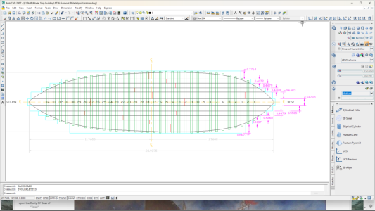
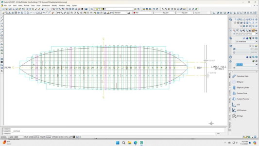
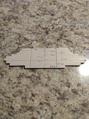
Below is the current state of my CAD file showing the layout of the bottom of this vessel and the size of the strakes, number of planks per strake, and the positioning of the floor timbers. The red lines on the strakes denote where planks were actually joined to make up the individual strakes. These planks were not joined in the middle of the floor timbers. The floor timbers were too narrow for that due to the 1" diameter treenails used to attach the planks. Instead, the planks were joined together via 1.5" thick 'Butt-Block Splices' located 'between' floor timbers and/or wherever the joints landed, and butt-blocks could be effectively placed. If you look closely, you will also note that the bottom planking strakes are of various widths. Not a lot of consistency at all. I suppose that the builders were just using whatever widths of lumber that they had on hand in order to simply fill in the bottom of the boat. Last but not least... the floor timbers, themselves, 'also' vary in 'their' widths too! Not a lot of consistency there, either.
Even though these 'oddities' might look a bit 'off-putting' to some folks, I'm going to do my best to reflect them as they truly are/were in this scale build.

1744562352103.png
 
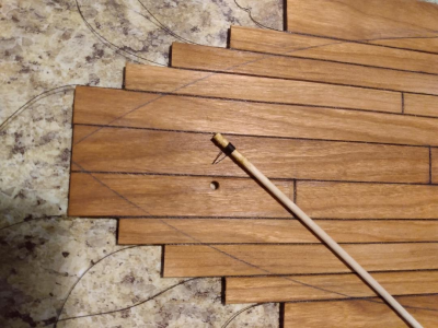
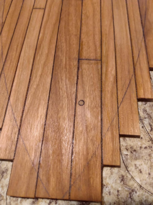
As she was built, the Gunboat Philadelphia was started with the bottom planking being laid down. The flooring timbers were then positioned atop the bottom planking and temporarily 'toenailed' to the bottom planking, just to hold things together, until the bottom planking was effectively attached to the floor timbers via 1" wooden trunnels. Evidence of these temporary toenails are noticeably present on the actual Philidelphia as she sits in the museum today. After the bottom planking and flooring timbers were securely tree nailed together, the temporary toenails were removed, and the bottom was cut to its shape. Some folks wonder if this gunboat was built right side up, or upside down and flipped. The boat was a bit too big and awkward to be flipped. It was built right side up. Evidence of 'this' is due to a 2.75" diameter hole that was drilled through the bottom planking, approximately 48" forward of the sternpost... a hole that was plugged prior to launch. This hole was likely used as a drain to remove rainwater while the boat was being built in its upright position.
 
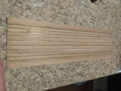
Bottom planking Strakes have all been cut to various widths, as shown in the drawing.

1744562619716.png

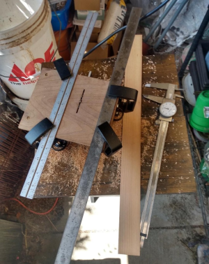
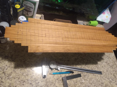
I used my cheap 4" Amazon table saw, steel rules for front and back gauging, and small 'C'-Clamps to hold my gauges in place. I use the calipers to set the cutting width of my pieces. It's kinda 'fiddly' to set up for each cut but works very well and is actually quite accurate for such a 'redneck' rig like this! "Who needs an expensive table saw!" ;)

1744562897622.png
 
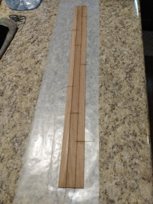
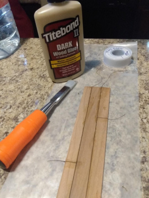
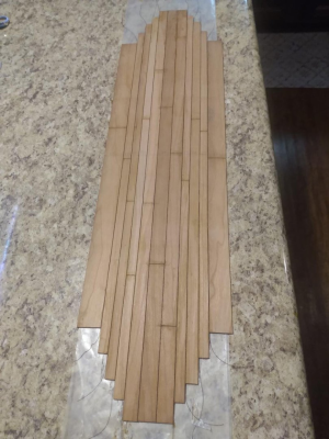
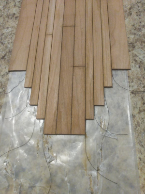
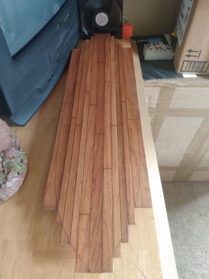
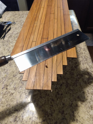
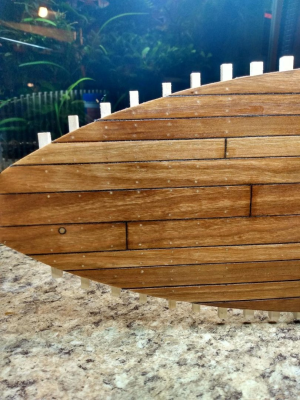
Beginning the bottom planking and caulking. I'm starting from the center of the bottom and working my way 'outwards'. The bottom is being assembled 'upside-down' (unlike the 'real' building method of this vessel). I'll add two strakes every day until the oversized bottom blank is completed and caulked, then I'll cut out the shape of the bottom. I'll only do two strakes per day because I'm trying to avoid any distortion and/or warpage due to the long joints and glue runs. I'll be gluing the new strakes to an already glued up 'sub-assembly' that has cured and is rather stiff.

The strakes are full length. I'm adding the illusion of 'planks' within those strakes via a chisel. The 'caulking' is .0078" diameter "Tuff-Cord" that would represent a 3/16" caulking seam on the full-sized vessel. I lightly sanded the edges of all the strakes to form the tiny groove needed to accept the tuff-cord. To insert the caulking, I run the thread through a puddle of glue, lay it in place at the start of a groove and just run my finger down the thread's length. The thread pretty much finds the grooves all by itself. I then give it a wipe with a paper towel, to remove excess glue, and let everything dry. The tag ends are cut after drying. The caulking is fairly secure once the glue dries, but it will also be sealed in permanently with a clear topcoat after the bottom is completed and finish sanded, prior to cutting out the shape of the bottom.

1744562977562.png

1744563005718.png
 
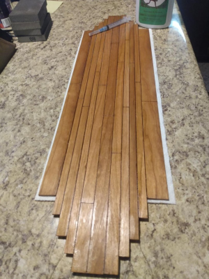
Bottom planks/strakes have now been glued up and the 'Oakum' caulking has been hammered into the caulking seams. Next up... I need to better seal those oakum caulking seams with a proper topcoat 'bead' of 'pitch'.... stay tuned!

1744563185015.png

1744563208377.png
 
What I've done is put a light coat of Tung Oil on the entire bottom to somewhat seal the wood. I've also filled the caulked seams with a thick layer of Tung Oil to represent a 'pitch' cap/layer atop the simulated oakum. I chose Tung Oil because it has a rich, dark, somewhat copperish color to it if applied thick. The thick Tung Oil atop my black thread Oakum should produce a nice looking and well blended color for my caulking seams. Once the thick tunnels filled with Tung Oil have finally cured within my caulking seams, I'll sand the bottom to lighten up the color of the planks and strakes. This should produce a very nice contrast between the lighter colored surface of my planks and the darker, multi-colored caulking seams. You'll also note how covering the 'Tuff-Cord' Oakum with Tung Oil 'pitch' produces a 'rippled' surface within the caulking seams. This is another effect that I am desiring. I've made pitch before, back in my flintknapping and primitive archery days. It's hard to get hot, tacky and gummy pitch smoothed out to a slick, smooth finish. I'm sure that shipbuilders once had the same problem. This is where the 'Tuff-Cord' comes in handy. The Tung Oil will soak in and take on the same surface shape of the cord. After a couple of thick applications, the ripples will smooth out a little, but not entirely. The caulking channels will always have a slight ripple effect to them, unlike the end result should plain glue be used as a filler. Yes, it's a lot of extra work, but I feel as though the end result/effect will be well worth the additional effort.

Here's the bottom... Tung Oil drying.

1744563429962.png

1744563542347.png
 
Outline of hull bottom. When this photo was taken, Tung oil was drying, hence the small fan in the background.

1744563646525.png
 
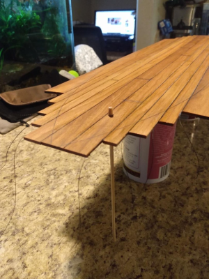
It's time to add that drain hole and make a plug for the bottom. I can't have my gunboat filling up with rainwater while it's being built!

1744563781089.png
 
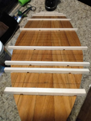
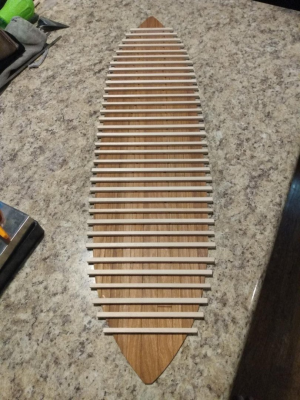
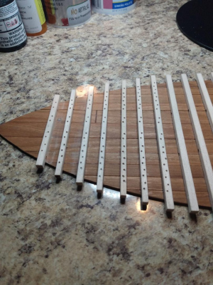
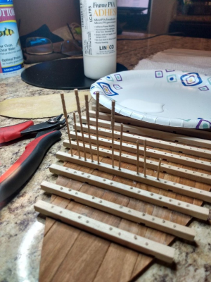
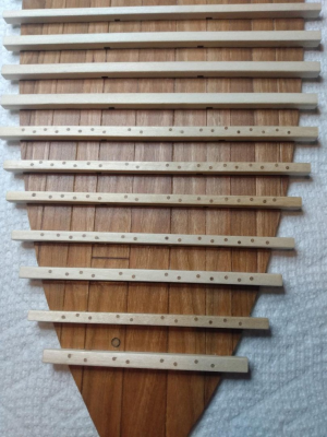
Flooring timbers and limber hole details have been worked out. The flooring timbers will remain long, as shown, until the frames have been installed. I'll then fair the ends of those flooring timbers to match the geometry created by the frames. The frames themselves will 'NOT' be faired. They will remain square and be placed perpendicular to the inner face of the outer planking. Not fairing the frames saved an enormous amount of time when this boat was being built. There was no time available for such a laborious task as fairing frames! Note that the limber channels are offset from the centerline of the boat. In a flat-bottomed boat, even slight inclines, as well as the natural movement of the boat can cause water to collect in various places. Offset limber holes help to ensure that water drains more efficiently towards the bilge area, or the 'bailing-well' as is the case with the Philadelphia. The five 'magenta' colored flooring timbers are the timbers that I'm going to temporarily leave out while testing the bottom for warpage. They will be installed once it is determined whether or not stiffeners will be needed.

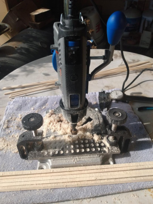
Time to get busy cutting and milling the flooring timbers...

1744564132833.png
 
Back
Top