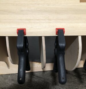
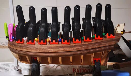
HIGH HOPES, WILD MEN AND THE DEVIL’S JAW - Willem Barentsz Kolderstok 1:50

With regards to point #1 I can tell you unequivocally that is not the case. Kolderstok simply does not make mistakes like that - I will stand and fall by that.
With regards to point #2, it is certainly possible that I made a mistake BUT again, if I did make a mistake there, the deck would not have fit as perfectly as it did.
Always interesting to know how things are made. It is no rocket science :)
When drawing the bulkheads of a ship (I use a CAD-program for this) I only draw one side. Same goes for the decks, only one side is drawn.
Then I mirror the drawings in the centerline, thus getting a perfect symetrical piece.
The drawing is send to the laser cutter, and they cut it all in a perfect shape.
 
Last edited:
Always interesting to know how things are made. It is no rocket science :)
When drawing the bulkheads of a ship (I use an CAD-program for this) I only draw one side. Same goes for the decks, only one side is drawn.
Then I mirror the drawings in the centerline, thus getting a perfect symetrical piece.
The drawing is send to the laser cutter, and they cut it all in a perfect shape.
I can only second that Hans.
 
Interesting and informative discussion regarding fairing techniques. I use something similar to what Maarten uses.
I use a 1" wide (actually I have several pieces with different widths and lengths) flexible metal strip with sandpaper adhered to one side. it's flexible enough that it forms easily to the curves but stiff enough that keeps my finger from deflecting the strip between bulkheads. It is a little more difficult to hold than the foam but so far, the results are good. Normally I hold the strip at the ends which have a small tab bent up and let the grit do its thing without putting excessive pressure on the strip. I've never used just a flat block of wood for sanding anything other than a flat piece. As they say, "Different strokes for different folks".:rolleyes:
Interesting tool.
Keep in mind a flat block will still only make line contact on a curve. So as you sand and roll across the frame, it will create an angle towards the adjacent frames while creating a flat surface for the plank along that angle.
So that’s why a flat file or sanding block still works on frames, because we want a flat surface for the plank to sit on. At mid ships where the frames are the same size, a flat block is the obvious choice. However you could use a round dowel wrapped with sand paper, it’s all still line contact regardless, because you are sanding a curved surface! ;)
Anyway, most importantly, I think a sanding tool should be fairly rigid to maintain the proper angle between frames. But if the hull is faired properly and there is enough contact area for the plank to be glued, then that will be sufficient, regardless of how you got there. ;)
In conclusion, I think the end goal is to fair the hull as accurate as possible to have the best planking outcome. And the better the frames are faired, the less sanding you will have to do! ;)
 
I should also mention an important technique I use. I don’t clamp my planks to the frames, however because I don’t use filler blocks, I will clamp the plank I’m adding to the previous plank in any areas that the new plank wants to bow or dip, and therefore doesn’t align with the plank next to it. This will cause a lot of sanding and can also distort the shape of the hull. So I clamp if needed as shown below…
2AB1843C-C651-4878-A5BB-BEBD1C53187E.jpeg
 
I should probably elaborate on the technique I learned, by using a sweeping motion. What I should have attempted to explain, is that while you roll down the frames from keel to deck, you also push towards the center of the ship some. So it’s an arcing motion, which I described as sweeping motion. So you are not going straight down from keel to deck, and not going straight from bow to stern, but rather a combination of both in one sweeping motion. So I should have said a sweeping motion in an arc. I think this helps the planks sit properly at any angle. I hope that makes sense? ;)
Dean, this makes perfect sense to me. Okay
 
@JDS73 Dirk's build log on how we sometimes have to take a step backwards to fix something that is not right or that we are not happy with.
And still I'm angry abouth Corel and there bad drawings ROTF. But I'm also angry abouth myself to. Because I was not sharp enough to see the major fault I made at the bow.
But now, in this stage, I can make jokes abouth it.

I deside to let the PW for a couple of weeks and do something els, like 2 Aibrush clinics and a other project (not wood). Clear my mind and try to find a solution to restore my fault.

Thanks again for your motivational posts in my building log and PM. If you did not did that, I think that I never had the motivation to go on with this model..
 
Last edited:
The yellow line represents the actual plank on the model. The green block indicates what I would call the fairing area of a sanding block for instance. I was taught to do fairing in a relatively straight line starting from bow to stern using a non-flexible sanding block and then moving up and down the hull in zones - but always working from the bow to the stern. But here you can see that on all the bulkheads marked with red lines, the plank falls out of the green block - so it is not in that particular fairing zone. And to make matters worse, on all those bulkheads the contact points are at a point where the bulkheads are considerably wider (more bulbous) than on the parts that fall in the green block.
Heinrich, the fairing area represented in green is not the correct area, IMHO. While you have to fair all the frames, you will never be able to fair them at once. The technics are to use only two or three neighboring frames (under pressure) for a single path. The fairing stick (not the block) must be straight and long enough to cover a max of three neighboring frames, it is also should be no wider than 1 or 1.5 inches wide. You can start from the stern towards the bow section and the motion should go from the top bottom of the hull at the same time. The foamed stick should be only used on curve\concave surfaces (Stern and Bow sections).
 
And still I'm angry abouth Corel and there bad drawings ROTF. But I'm also angry abouth myself to. Because I was not sharp enough to see the major fault I made at the bow.
But now, in this stage, I can make jokes abouth it.

I deside to let the PW for a couple of weeks and do something els, like 2 Aibrush clinics and a other project (not wood). Clear my mind and try to find a solution to restore my fault.

Thanks again for your motivational posts in my building log and PM. If you did not did that, I think that I never had the motivation to go on with this model..
Hello Dirk. I am very glad that my posting convinced you to carry on with your Prins Willem. This is why I do these build logs and why I take time with them to explain as much as I can - even my own mistakes! And with a Kolderstok model - you cannot blame the manufacturer. So, if something goes wrong, as in my case, there is only yourself to blame :D - not always easy, but always necessary!
 
Heinrich, the fairing area represented in green is not the correct area, IMHO. While you have to fair all the frames, you will never be able to fair them at once. The technics are to use only two or three neighboring frames (under pressure) for a single path. The fairing stick (not the block) must be straight and long enough to cover a max of three neighboring frames, it is also should be no wider than 1 or 1.5 inches wide. You can start from the stern towards the bow section and the motion should go from the top bottom of the hull at the same time. The foamed stick should be only used on curve\concave surfaces (Stern and Bow sections).
Hi Jim. Thank you for your contribution. The fairing area in green was not intended to show the area that will be covered at one time - it merely represents the TOTAL area that will be faired if you continue with linear fairing only - that is why doing it only like that, is not adequate. It was thus intended to show that following that process, would be incorrect. I agree 100% that the fairing tool has to cover three frames at the same time.
 
View attachment 277626

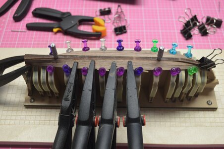
Same here only on a lot smaller scale. ;) Especially needed when you can't glue to bulkheads
Great minds think alike Ron! :) I must say your psychedelic-colored push pins are very snazzy - however those long-nosed clamps really look to be very handy to get into all those inaccessible places. I need to get some of those - so thank you for posting that picture and showing our members yet another variation on the correct theme to follow - it is much appreciated! Thumbsup
 
Then - to add some confusion in this nice fairing tutorial: the real Dutch ships from the 17th century were almost never exact symetrical :)
Hans, you are right and it is yet another example of how we as modelers are trying to create perfect models of imperfect subjects in real life. We are a strange bunch of bunnies indeed! ROTF
 
Great minds think alike Ron! :) I must say your psychedelic-colored push pins are very snazzy - however those long-nosed clamps really look to be very handy to get into all those inaccessible places. I need to get some of those - so thank you for posting that picture and showing our members yet another variation on the correct theme to follow - it is much appreciated! Thumbsup

Shhhh, I borrowed those from the Admirals cork board. Have since purchased my own. :)
 
Back
Top