• Ships of Scale has incorportated an extra level of security when you log In. Please follow on-screen prompts to acknowledge that you are not a robot via a "Check Box" or a "Pictorial Check Box Puzzle". This is needed due to higher level of AI Activity Security.
  • SUBSCRIBE TO SHIPS IN SCALE TODAY!

    The beloved Ships in Scale Magazine is back and charting a new course for 2026!
    Discover new skills, new techniques, and new inspirations in every issue.

    NOTE THAT OUR NEXT ISSUE WILL BE July/August 2026
  • Win a Free Custom Engraved Brass Coin!!!
    As a way to introduce our brass coins to the community, we will raffle off a free coin during the month of August. Follow link ABOVE for instructions for entering.

His Majesty's Ship Fowey (44) 1744 by AllanKP69

They can be printed on regular paper then glued to the wood but once the paper is wet with glue I find it is hard to work with. The label paper does not stretch or twist like paper with glue in my experience.

I overcame the rag-like properties of timber patterns on printer paper by using the top-of -the -line 96% white paper and giving it a heavy coat of brushing lacquer. I attach the patterns using Best Test rubber cement. Use a smooth but liberal coat on the timber stock and on the pattern back. Let it dry. Then join the two. The grab is instant so there is no fine adjustment.
When the patterns have done their job an old used Gem blade starts the separation. Most of the time the whole pattern peals right off. Th Gem blade gets under any stubborn shards. My thumb removes the rubber cement from the wood.

One 4oz applicator bottle - a quart to refill it - a quart of n-heptane to keep the cement at brushing consistency - cheap bulb pipettes to add the solvent.

The lacquer - The solvent is fierce. I use it in open air. I tape down all four edges of my patterns sheet with old fashioned crepe paper masking tape to a sheet of contractors demo model floor protection brown paper cut from a roll. Dry lacquer under the paper is a bear to defeat. NO aerosole lacquer EVER. My lungs are not evolved to deal with a coating of nitrocellulose. It is better not to turn materials that are not otherwise volatile into something that is. The solvent is bad enough - a particle mask will not filter an organic solvent - only activated charcoal or an independent air supply will. But open air and a breeze works and the solvents are heavier than air. A 50 cent 3" brush is good enough to apply the lacquer.
High Gloss - the stuff with added dirt does not hurt and if I have to use it - do not stir it. A gallon used to be twice the cost of two quarts, but gallons are now difficult to find and the price - well inflation has really affected it. One heavy coat is enough. More is not better. More makes the surface grabby.

I do not have the reference, and it is not Goodwin, but I remember that the max depth of the timber chock (butt chock) was 50% of the molded dimension where its at.
 
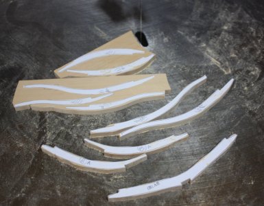
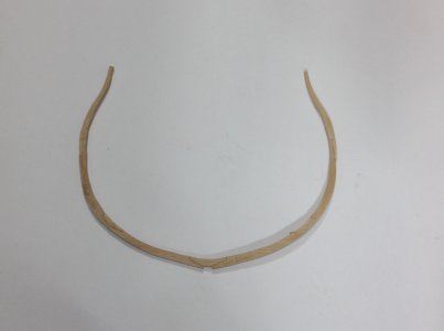
Frames. I am waiting on final decision on the framing dispostion as the team is traveling. In the mean time I can start making the frames. The frame drawings are printed onto label paper. Next step will be to cut each floor and futtock then peel the backing and stick the part onto the pre-thicknessed boards. The floors and first futtocks are the same thickness, 12.5", the second and 3rd futtocks are 11.75" and the top timbers/upper most futtocks are 11" broad. They can be printed on regular paper then glued to the wood but once the paper is wet with glue I find it is hard to work with. The label paper does not stretch or twist like paper with glue in my experience.

Two frame drawing examples before each piece is cut and attached to the wood. The first is from the drawing board. The second is another frame printed on the label paper
View attachment 617474View attachment 617475
Starting with the frame is a interesting and labor intensive part of the build, Allan. Will follow it with great interest. Till now it’s looking very promising.
Regards, Peter
 
the max depth of the timber chock (butt chock) was 50% of the molded dimension where its at
Good point, thanks Dean. I just looked in Goodwin's book The Construction and Fitting of the English Man of War. He describes the timber chock or anchor piece for ships from 1710 to 1750 but I cannot find any information on the sizing in the book. A conundrum as there are about 10 drawings of the chocks in TFFM Volume I and none of them are 1/2 of the molded dimension, but rather, about 2/3 or more. Without confirmation based on contemporary sources I am not sure if 1/2 or 2/3 is correct. The problem gets big when making the frames fore and aft as the chocks need to be cut at the same angle as the bevel of the frame. None of them will be seen from the side once the frames are raised but I would love to find contemporary information on these. I do not have Ollivier's book but if anyone out there has it and it gives this information PLEASE let me know. I checked the scantlings in the Establishments, The Shipbuilder's Repository and David Steel's The Elements and Practice of Naval Architecture and found nothing so far regarding the chocks.

Regarding, glue on drawings is there is an advantage to using contact cement and solvent and bulbs and bottles and does it do a better job? If it does it would definitely be worth a try. Right now I print, cut and peel.

Thanks again Dean

Allan
 
Without confirmation based on contemporary sources I am not sure if 1/2 or 2/3 is correct.
From the practical - it does not matter. The frame chocks will be almost impossible to see anyway.
They only matter on a section model. - You should also consider doing one for the midship in addition.
I do not even consider them for my style. It is the fore quarter and aft quarter where the bevel is significant that cause me to consider them not worth the trouble. In your place, I would consider splitting the difference and do 0.6.

In your place, I would stick with POF, but where the framing is behind planking, I would choose practical over authentic.
No filling frames, combine them into a bend. Or a solid wall and full frames all the way. On a model there is no needed to worry about loss to bevel. Plotting cants and going that complex geometry when it is hidden?
I checked to see if my prejudice against cant frames was shared and found many if not most of the 1670's Navy Board stylized frame masterpieces were full frame up to the hawse. And I believe full frames up to the transoms.


Regarding, glue on drawings is there is an advantage to using contact cement and solvent and bulbs and bottles and does it do a better job? If it does it would definitely be worth a try. Right now I print, cut and peel.
I use rubber cement - the wrinkle-free - paper stuff.
I much prefer Best Test to Elmer's - quality matters here. An even coat, but a thick one too.

It is new to me that DAP contact cement is also a rubber cement, but it is a totally different formulation. That stuff just does not want to go away. It is lousy after 20 years or so for house or furniture construction which is what it is for. It is totally contraindicated for any use on a model. I have up to now used it to bond paper backed and now cloth backed sanding media to the Maple platen on my Larson model thickness sander. No organic solvent that I have tried will totally remove it without a ton of work, but I have never tried n-heptane - so I have some hope there.

I am looking at your pix of your patterns and I am having the thought that by not dissembling the patterns into individual timbers and doing close packing before printing you will use a lost of Avery material that ain't cheap.
I cycle R G B instead of black to idiot proof things -me being the one making idiot mistakes unless I plan against it.
 
In your place, I would stick with POF, but where the framing is behind planking, I would choose practical over authentic.
We are on the same page in a lot of things. That is exactly what will be done. Every third frame, where t will be planked over. This leave less than 3/4 inch assunder so plenty of surface area to glue the planking without worrying about flat sections like the kits that have too few bulkheads.

I checked to see if my prejudice against cant frames was shared and found many if not most of the 1670's Navy Board stylized frame masterpieces were full frame up to the hawse.
The actual ships had all square frames until about 1710 if I remember correctly and that is my plan for now. It made drawing up the frames using the body plan station lines much easier.

you will use a lost of Avery material that ain't cheap.
I stopped using Avery years ago. There are equally good label papers for half the price.

What is RGB. Really Good Build??? :)
 
What is RGB.
Painter19 defaults to the triangle - circle and three slides for color selection.
I am all about quick and dirty so sliding the top one all the way is 255 000 000 = Red
middle G green - bottom B blue
If each face is a different color and cycling thru three I know Red is always deadflat face when R G
Green always when G B and Blue when B R.
More efficient would be Magenta - Cyan - Yellow but this way any one color uses all three nozzles
My Ecotank gets cranky if it sits idle for longer than a week.

I am guessing deadflat so far? I am waiting to see how you do the bevel when both faces' shape is different and how you align the partners in a bend.

Your cut faces are a lot smoother than mine, so I am betting scroll saw?
I use a Taiwanese 9" bench bandsaw with 3-4 TPI - cuts as fast as I care to push thru 0.25" stock.
Castelo is dense.

The actual ships had all square frames until about 1710 if I remember correctly
Well that explains it, and here I have been thinking that they avoided cants because they were too much work to justify the difference in look.
 
I am guessing deadflat so far?
The only frames that will be exposed will be the dead flat frames so the chocks are not an issue. For the rest they will be planked over so I may just go with scarphs. The moulded dimensions of the floors and futtocks will be over sized as needed to account for the angle that will be sanded as needed going aft and forward.
I am betting scroll saw?
You are right, I use a scroll saw. I had a band saw that rarely saw the light of day so I got rid of it years ago. I know there are uses but with a full size table saw, planer and a Byrnes thickness sander I have not missed it to make slats of wood.

Allan
 
Allan,

This only impacts Fowey peripherally. Where the physical remains conflict with the design, this might inform about the reason.

With the Navy Act on the statute books, Anson and Sandwich turned their attention
to the six royal dockyards, the largest employer in the mid-eighteenth-century British
economy, with a labour force of about 7,000 men in 1749. They recognised that there was a
longstanding need to increase the efficiency of the dockyards, whose failings had become
increasingly apparent during the last war. The navy was also faced with the need to make
peacetime economies as the Government sought to reduce the national debt by cutting
expenditure across the board. Although the Navy Board had reduced the dockyard labour
force at the end of the war, numbers were still high compared to earlier periods and the
Admiralty believed there was scope for further reductions. It increasingly questioned the
effectiveness of the Navy Board’s management of the dockyards because it was reluctant to
make further cuts to the labour force or to address concerns about excessive costs and delays
in completing ship repairs. It was also unwilling to deal with a conservative workforce that
was resistant to change. By 1749, the death of Jacob Acworth and the retirement of the
elderly Comptroller Richard Haddock raised hopes that at least one barrier to innovation
had been removed and that Admiralty intervention in the dockyards might produce much-
needed changes.

On 9 June, the Admiralty Board decided on its next steps. With the Navy Board reluctant
to answer its repeated requests for information, Sandwich, Anson and other members of the
Board decided that they would visit every yard themselves.” A visit would be unprecedented
but was essential if the Admiralty were to make an independent assessment of the yards’
performance, which would then place it in a much stronger position in future dealings with
the Navy Board. It is not clear who first proposed the idea of an Admiralty visitation, but
there is no evidence that Anson had any particular interest in dockyard management or
reform and during his eleven-year tenure as First Lord, he never made another inspection
of the yards. Sandwich, on the other hand, introduced annual dockyard inspections when
he returned to the Admiralty as First Lord in 1771.

The Admiralty visitations in the summer of 1749 were intended:
To examine into & become acquainted with the abilities and conduct of the officers,
the sufficiency of the workmen, the condition of the ships and magazines, together
with what works were carrying on, that such reformations might be made as should
be found needful to prevent any unnecessary expense.”*


Inspections were expected to lead to greater productivity as they hoped to ensure:
That the officers paid due obedience to their instructions, that the several rules
& orders for the government of the yards were punctually carried into execution,
that the ships of the Royal Navy were kept in condition for service, and the money
granted [by Parliament] was frugally expended.”

Anson was present at the visits to all six yards, which began with an inspection of the
Woolwich yard towards the end of June.** Although examples of good practice and a trial of
piece work (‘task work’) - payment according to the work produced as a means of increasing
productivity - were found, the visiting party soon uncovered numerous problems and
abuses: standing orders were largely ignored, buildings had been neglected, the men were
poorly supervised and accounts were often in arrears. The was evidence of over-manning,
while the ships in Ordinary (out of service for repairs or maintenance) were not being prop-
erly maintained. There were too many old and underperforming workmen who could not
be removed and for whom there was no pension provision. The dockyard workers’ right to
take ‘chips’ - timber offcuts which they could use to heat their homes - was widely abused
and large quantities of valuable wood were routinely stolen and resold. Another common
abuse was the payment of overtime for hours that had not been worked so that dockyard
managers could match the significantly higher wages paid to shipwrights in private yards,
particularly in wartime.

The inspections were completed by mid-August and a list of 14 recommendations was
agreed upon and sent to the Navy Board in November. The Admiralty believed that the
management of the yards would be strengthened if standing orders were complied with, the
men mustered frequently, and accounts submitted on time. There was scope for reducing
the number of artificers and their servants. Ships should be inspected four times a year and
ships in Ordinary should be better maintained, but vessels that were beyond useful service
were not to have money spent on them. A programme to repair the fleet should be under-
taken. Finally, the Admiralty supported the introduction of piecework in order to increase
productivity.

When the inspection tour was completed, Anson hoped that the ‘public will reap some
benefit’ from the Admiralty’s efforts, but in this he was to be disappointed.*” The Navy Board
did not write to yard officers about the outcome of the visitation until March 1750.

Ref. Anson Royal Navy Commander and Statesman, 1607-1762
Anthony Bruce
Helion & Company Warwick, England 2023

 
Thanks Dean

No posts recently but sooner than later as I have been cutting floors, futtocks, and top timbers. Lot of wood, sawdust, and a few broken scroll saw blades. The dead flat will be as mentioned before, framed with chocks and scarphs and those that will be planked over are all scarphed. With a hot garage I have taken to doing what I can in the house but the making of board stock on the table saw and cutting the parts of the frame with the scroll saw are a bit of a chore with the heat. And of course golf gets in the way in the mornings when the garage is a reasonable temperature. Priorities need to change I guess.......

Allan
 
Last edited:
The frames in the deadflat will be exposed so chocks and scraphs are used. The rest of the frames will be planked over so I went with all scraphs. The siding of the floors and first futtocks is 12.5", the 2nd and 3rd futtocks are 11.75" and the top timbers and upper futtocks are sided 11". The moulded dimensions at the heads of each are taken from the 1745 Establishment. The moulded dimensions are "fat", especially fore and aft of the dead flat so there is material to sand and form the curvature as needed. 24 frames down, more to go.
Allan

1785337144660.jpeg
 
Last edited:
Allan,

Re: your framing question on MSW.

Torrington has stations at 3 bend intervals. 78" except for 0 to 1 which looses 13" because of the skip step necessary to have the floors on the away side of each station.

78" / 6 = 13" You have the necessary 1/2" air gap with every frame. The bends will have 1/2" chocks as "washers" at every thru bolt.
As less technical model would be 13" for each station bend or 12.5" and wider air gaps.

An odd numbered station interval complicates.
It can be:
#1 all bends = 1/2 of bend - bend - bend - 1/2 of bend
or
#2 1/2 of bend - singleton - bend - singleton - 1/2 of bend
or
#3 1/2 of bend - singleton - singleton - singleton - singleton - 1/2 of bend

The bend in the middle of #2 would have to its floor on the wrong side to hold the pattern.

On the sea floor - I am betting that it will be 12.5" 1/2" 12.5" 1/2" 12.5" 1/2" 12.5" 1/2"
or
If I could keep the inspector at bay
12" 1" 12" 1" 12" 1" 12" 1"
The washers/chocks are probably Pine and being 1/2" or 1" got ett fairly quickly.
If twer me in the yard - I would go with all bends. They are probably easier to rotate from flat to vertical without dealing with weakness of a singleton's butt joints.

The final result would look the same. The spacer chocks were probably placed between the singletons and their neighbors at some point in the raising sequence.
 
Thanks Dean. :) :) :)
Torrington has stations at 3 bend intervals. 78" except for 0 to 1 which looses 13" because of the skip step necessary to have the floors on the away side of each station.
Do you have the contemporary information for Torrington (44) 1743 framing? I have her six plans from RMG but nothing that shows the R&S or anything else about the framing unless the distance between the station lines are of significance. The Fowey and Torrington have length on the GD and breadth that are nearly the same so info on Torrington might be very useful.

I am hoping there is enough evidence on the wreck to determine the sequence of frames. Any and all information is GREATLY appreciated

Allan
 
Allan,

All that I have is ZAZ2290.

I have the for
ZAZ2010
ZAZ2177 #
ZAZ2236
ZAZ2278
ZAZ2279
ZAZ2290 #
ZAZ2291
ZAZ2296 #
ZAZ2297
ZAZ2298 #
ZAZ2299 #
ZAZ2300
ZAZ3715
ZAZ3716
ZAZ3717
ZAZ3718
ZAZ3719

The # = there are full size prints

I work under = all of the design plans are copies of the same origin official 1741 Establishments plan.
Most if not all of the sisters in this class were built in private yards
For me, one plan is as good as another - Each yard needed a copy - The "intern" tasked with doing the tracing would probably only draw what was absolutely necessary.

There are no 1741 scantlings - so it was still 1719 40-gun numbers - The difference is about gunports anyway.

The resolution for the NMM JEPG is too low for me to determine the station numbering/lettering.

The station intervals on design plans define the framing.
For 1719 R&S 30" floors sided 11"
Diamond 40 1723 R&S 30" stations 90" intervals
30" - 22" wood = 8" space.

For 1741 R&S 26" := stations at 78" intervals - 3 R&S per interval = 78 / 3 = 26
26" - 22" wood = 4" space

The 1745 Establishment R&S 28" floors sided 12.5" The 78" interval is fixed by the plan.
26" - 25" wood = 1" space which was probably divided into two 1/2" spaces.

The number of guns and thus the weight was increased from 1719 to 1741 The 1745 Establishment could be the formalizing of the scantling changes made for the 1741 design change OR they could have been variations in the increase - "experiments" by the master shipwright in each yard. As I posted above - each yard was probably the private kingdom of its master shipwright. Any predictable standard probably had to wait until 1745 was official.

In my view for you 78" is a fixed point - the sea floor will determine the wood.


editorial:

To me, it says a lot about the relative value afforded to this class that the building was shunted off to private yards - probably those yards with political connections to those MP controlling the purse.

Too short and for the width and too high relative to anything. Hopeless against a frigate with same number of guns. Way to small to be of any use in a line of battle - even though it is officially a 5th rate liner.
I still cannot understand the thinking behind base 10 classification of rates. A full gundeck was 26 or 28 tubes.
Absurd from first proposal - it says much about money - power - and stultified tradition and aristocracy that it continued far past the time when it was known to be non-functional and actually dangerous.
 
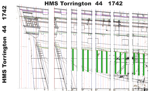
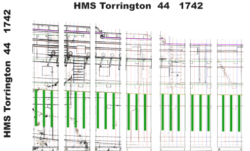
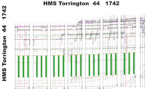
This is probably of little of no use to you but here is my framing plan for the 1741 Establishment 44's:

Torrington Station frames  3.pngTorrington Station frames  2.pngTorrington Station frames  1.png

I use stylized framing. It looks like Navy Board - but is not. The spaces are only in the futtock 1 frame. The actual F1 is only 5" long - and I name it Navall timber - after the timber that lived where futtock 1 lived when the conversion from shell first to frame first occurred.

The green bars are the spaces above the turn of the bilge.
The stations stop short of the beakhead bulkhead. I only use full frames. I want to take the framing all the way to the BH. I had the loft the BH shape.

UPPPS : I did not subtract 28 to AP from ST to AP so there is duplication in the last section aft. The timbers from AP to ST (stern) resemble a DA haircut or wings. Oh yea - I also had to loft the shape for AP.
 
Last edited:
Florida came under British control in 1763. Fowey was lost near what is now south Miami Beach in 1748. The War of Jenkins' Ear ended in 1748. There was more going on than wrong place wrong time in hurricane season.
 
Allan, since, this is a commission, I assume that time is money. Therefore, for the frames that will be planked over, why not use the Hahn method of assembling two ply blanks from mitered straight pieces and then cutting to shape with your scroll saw?

Roger
 
Or, do the framing behind the planking as a solid wall of Yellow Poplar frames using the stations as the only patterns needed.
If the build was 1:60 - I have the patterns already done. It would take a re-do of two steps to get the same for 1:48.
I am willing to donate the time. The most time consuming part is already done. Part two - defining the timbers and placing the locator -alignment pins is about a day's work. Isolating and arraigning the timbers for print out is just tedious rep.
 
Back
Top