
-

SUBSCRIBE TO SHIPS IN SCALE TODAY!
The beloved Ships in Scale Magazine is back and charting a new course for 2026!
Discover new skills, new techniques, and new inspirations in every issue.
NOTE THAT OUR NEXT ISSUE WILL BE July/August 2026 -

Win a Free Custom Engraved Brass Coin!!!
As a way to introduce our brass coins to the community, we will raffle off a free coin during the month of August. Follow link ABOVE for instructions for entering.
You are using an out of date browser. It may not display this or other websites correctly.
You should upgrade or use an alternative browser.
You should upgrade or use an alternative browser.


- Joined
- Apr 20, 2020
- Messages
- 6,425
- Points
- 738

it's looking very impressive
")


Thank you Dave for the pointer. I found it on page 27 of the Anantomy of the Ship. In fact, I see that the ship carried a smaller anchor on the port and starboard sides behind the second large anchor. I won't be installing those, though.
Your model looks very impressive. I am still making the deck and hull fittings and hope to have these in situ by the end of the year.
Your model looks very impressive. I am still making the deck and hull fittings and hope to have these in situ by the end of the year.
Unfortunately my kit arrived without the anchors included, I was instead packed and additional six cannon, not a great help. Blue Jacket did have the four anchors I needed.
Occre usually provide any parts which are broken or missing free of charge under their guarantee scheme. Their website gives more details. There is a form there to be filled out online. Just input the model number of the ship and the parts required. I had to wait about 10 days for mine to arrive. I ordered also a 1:1 scale drawing of the Endeavour looking on the port side, which is now on the wall behind my workbench.
Thanks, good to know. On the anchors. On page 78 of the same book is a drawing of second anchor placement. I am including some pictures of how I installed them.


Thank you Dave for sharing the positions of your anchors with me. I am now clearer how the secondary anchors are tied. Did you drill some extra holes in the deck for the ropes or just hang them on the hull?
A couple of photos attached from me showing the drawing I mentioned earlier and of my anchors. Pity Occre doesn't have drawings onto the bow and stern. I bashed the anchors somewhat, using the original aluminium anchor from Occre, but making my own stocks out of some wood I had from a previous hobby. I went along with Marquart's book and wrapped the anchor rings with sewing thread. I used very thin copper strips to manufacture the bands and the ends of cut-off nails in holes drilled before (0,7mm) to imitate the nails in the blocks. All metal parts burnished to achieve a more or less authentic finish. The only thing I'm not sure off is were the anchors mid 18th century tied using rope or chains to tie them down.
I see you from the photo you didn't use the Occre supports for the hand guns (Falconetts). Nor did I. They were too small and didn't look good. Have a good day.
Nice job on the anchors. I drilled the two holes outside the hull to accept the anchor rope and glued into a 1/4 inch deep hole. On the deck I also drilled two holes to simulate the anchor ropes went through the hull. I then place the anchor ropes into the holes and glued them in place. I them ram the lines thought the winch and down two more drilled holes into the hull.

Last edited:
Here are the anchors I built. I used copper tape for strapping and painted them black. I used cut off nail head for the bolts..JPG")
I drilled small holes into the anchor stocks and cut the heads off the nails provided for planking. I set them into the holes and glued them in. The opposite sides look the same. I shaped the stocks from scrap wood drilled holes to receive the anchor tops. The black straps are made from copper tape used on stained glass. I then painted them black.
I did the same regarding the rivets. However, I made the stocks out of two pieces of wood, made the slots to accomodate the ends of the anchors and glued them together with the anchor in situ using white glue. When dry I then proceeded with drilling the holes for the rivets and manufacturing the bands. I rubbed the burnished anchors to give them an iron look and, finally, I glued the anchors into the stocks using a 2 component glue, before wrapping the rings with thread.
Last edited:
BTW, If you're interested, and maybe you have found it already, there's a good video (
) from Tom Lauria on a useful template to make good belayed rigging lines.
.... not that your loops are bad, Dave. They are good!
I will soon commence fixing blocks to the rings in the deck for the cannons, the rudder and the like. Were the blocks attached directly with rope to the eyes or is it better or more authentic to fix each block to a hook, which was then hooked into the rings?
Continuation of my build log.......
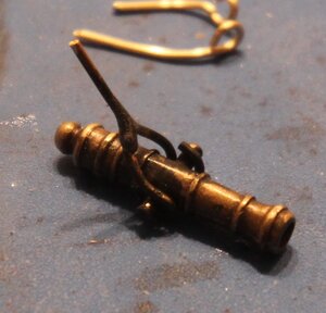
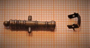
Making the hand cannons or falconettes. The supports supplied by Occre, I felt, were not particularly good, so I decided to make my own. To do this I made fixtures to bend the wire (0,8 mm Dia.) and to hold the three elements of the support for soldering. I noticed after burnishing the supports, the solder would not adhere to the wire. Another lesson learnt. Photo below shows the original support .


For the knob on the end of the handles I cut off the top of railings I had from a RC model I built years ago and soldered them in place.

Making the hand cannons or falconettes. The supports supplied by Occre, I felt, were not particularly good, so I decided to make my own. To do this I made fixtures to bend the wire (0,8 mm Dia.) and to hold the three elements of the support for soldering. I noticed after burnishing the supports, the solder would not adhere to the wire. Another lesson learnt. Photo below shows the original support .
For the knob on the end of the handles I cut off the top of railings I had from a RC model I built years ago and soldered them in place.
Attachments
Next it was the turn of the dead-eyes for the hull. For these I used brass wire, 0,8 mm Dia. I wasn't sure which method to use, as the Endeavour sort of lies on the border of a single tie method, affixed to the hull with a plate, and with chains, which I believe came around the middle of the 18th century.
Below is an image showing the 6 stages of production.

Ready for burnishing and soldering.

The finished product. I will bend them accordingly when fitting to the hull .

Below is an image showing the 6 stages of production.
Ready for burnishing and soldering.
The finished product. I will bend them accordingly when fitting to the hull .
The aluminium anchors supplied by the manufacturer were ok and more or less true to the period in both scale and form. Only two supplied in the kit and I organised two more. The Endeavour carried at least 4 anchors.
The anchor stocks were to be made from several pieces of thin strips and glued together. I didn't like this method, so I decided to make my own stocks out of solid wood. I duly cut up 8 pieces for four anchors, manufactured the slots for the anchor shaft, half deep in each stock half and glued the two halves together. I used thin copper plate for the bands and cut-offs from nails to simulate the rivets. I burnished the metal anchors and rubbed them to give them an iron-look. Following on, I glued in the anchors into the stocks, made 4 rings and wound each ring with garn.
.JPG")
.JPG")
The anchor stocks were to be made from several pieces of thin strips and glued together. I didn't like this method, so I decided to make my own stocks out of solid wood. I duly cut up 8 pieces for four anchors, manufactured the slots for the anchor shaft, half deep in each stock half and glued the two halves together. I used thin copper plate for the bands and cut-offs from nails to simulate the rivets. I burnished the metal anchors and rubbed them to give them an iron-look. Following on, I glued in the anchors into the stocks, made 4 rings and wound each ring with garn.


More to come.
Last edited: