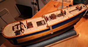
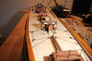
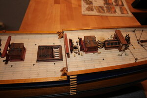
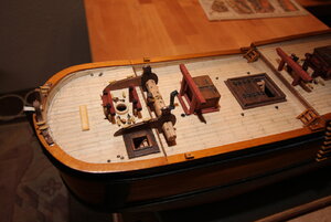
-

Win a Free Custom Engraved Brass Coin!!!
As a way to introduce our brass coins to the community, we will raffle off a free coin during the month of August. Follow link ABOVE for instructions for entering.
-

PRE-ORDER SHIPS IN SCALE TODAY!
The beloved Ships in Scale Magazine is back and charting a new course for 2026!
Discover new skills, new techniques, and new inspirations in every issue.
NOTE THAT OUR FIRST ISSUE WILL BE JAN/FEB 2026
You are using an out of date browser. It may not display this or other websites correctly.
You should upgrade or use an alternative browser.
You should upgrade or use an alternative browser.
Very nicely done. Your deck work is amazing.
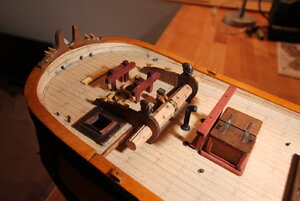
Thank your Dave for the compliment coming from someone who is doing a great job with his own ship. I have a question regarding the blocks on the deck near the bow around the mast between the two stock supports. See photo last but one. Occre say on their drawing showing the deck from above that there are three blocks, but there are 4 eyes. As you are much further into your build, is this correct, or is there a mistake on the drawing?
Very good work, and informative photos - many thanks for taking the Time and Sharing with us
I went with the Occre plans for the block placement on the deck. I reviewed the drawings in AOS book and decided to use the kit plans. It worked out fine when rigged.
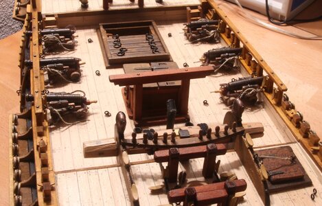
I decided to work from the middle of the deck outwards so that peripheral parts wouldn't get in the way when mounting the deck furniture, cannons etc. Next up was the manufacture of the cannons themselves. The carriages and the barrels originated from a project many years ago and I used these instead of the carriages from the kit manufacturer. I had to mount the railing supports to the hull first, though, to attain the correct position of the cannons on the deck.
The image below shows the steps I took to make the cannons. The image is from Marquardt's book of the Endeavour:
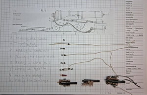
The blocks are 3mm, made from walnut by a company in the Czech Republic. I made the hooks from 0,6 mm Dia. brass wire and then blackened them. The garn is 0,25 hemp. I made the wedges out of left-over wood strips. The wedge handles are made out of toothpicks. I cut the toothpick and turned it down in a Dremel to form the handle using round and square needle files as shaping tools and glued the handle into the end of the wedge. I glued in wood at the front of the carriage as a support for the barrel and filed it down with a round file to the correct height and shape.
Step 8 shows the almost completed cannon set-up. The last step before fitting to the deck will be to mount plates out of copper strip onto the carriages over the spindle ends to retain the barrel in position.
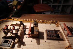
The only thing I am not sure of is how the carriage is secured to the deck using the hook at the back of the carriage. Occre doesn't go in to this in detail. Maybe someone building an Endeavour can give me some pointers, which would be very much appreciated.
I guess the fiddly bit will come when attaching the completed cannons to the decks and railing supports. When finished, I will submit images of them in situ.
The image below shows the steps I took to make the cannons. The image is from Marquardt's book of the Endeavour:

The blocks are 3mm, made from walnut by a company in the Czech Republic. I made the hooks from 0,6 mm Dia. brass wire and then blackened them. The garn is 0,25 hemp. I made the wedges out of left-over wood strips. The wedge handles are made out of toothpicks. I cut the toothpick and turned it down in a Dremel to form the handle using round and square needle files as shaping tools and glued the handle into the end of the wedge. I glued in wood at the front of the carriage as a support for the barrel and filed it down with a round file to the correct height and shape.
Step 8 shows the almost completed cannon set-up. The last step before fitting to the deck will be to mount plates out of copper strip onto the carriages over the spindle ends to retain the barrel in position.

The only thing I am not sure of is how the carriage is secured to the deck using the hook at the back of the carriage. Occre doesn't go in to this in detail. Maybe someone building an Endeavour can give me some pointers, which would be very much appreciated.
I guess the fiddly bit will come when attaching the completed cannons to the decks and railing supports. When finished, I will submit images of them in situ.
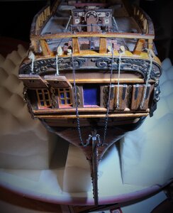
I spent today making the shutters for the stern windows. These were bashed, as Occre doesn't include these in their kit. I went against the manufacturer's instructions and ommited the middle window, as the original Endeavour didn't have this window. I will tie all the ropes, including the rudder chains onto the hull when the rear and side railings have been installed.
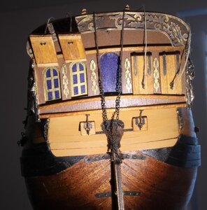

Stern almost completed...
Hi Dave, @Dave Teel
Can I bother your for some information concerning the position of the channels?
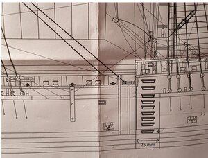
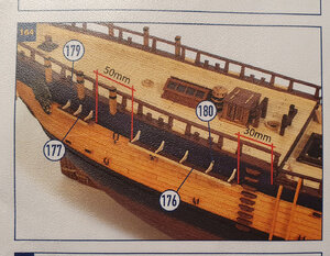
During preparation for the assembly of the mizzen channels onto the hull according to photo 164, I noticed when checking the position of the middle channel that there is a discrepancy in the dimension between the drawing (scale 1:1) and the photo. On the photo the distance from the vertical edge of the deck to the edge of the first mizzen channel is 30 mm. The distance according to the drawing is 25 mm. See images below!
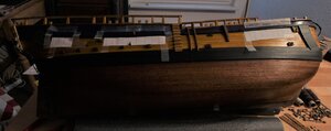 I I understand that I should be following the photos, as the drawing would normally not be available, I believe though this to be an important dimension, as it affects the angle of the dead-eyes to the hull and, ultimately, to the rigging and I want to get it right. Which dimension did you apply to your model and are the distances according to your experience for the other channels in the assembly instructions correct?

Hi Dave, @Dave Teel
Can I bother your for some information concerning the position of the channels?
During preparation for the assembly of the mizzen channels onto the hull according to photo 164, I noticed when checking the position of the middle channel that there is a discrepancy in the dimension between the drawing (scale 1:1) and the photo. On the photo the distance from the vertical edge of the deck to the edge of the first mizzen channel is 30 mm. The distance according to the drawing is 25 mm. See images below!
 I I understand that I should be following the photos, as the drawing would normally not be available, I believe though this to be an important dimension, as it affects the angle of the dead-eyes to the hull and, ultimately, to the rigging and I want to get it right. Which dimension did you apply to your model and are the distances according to your experience for the other channels in the assembly instructions correct?

Last edited:
Moving on to the bow work adding the forward pair of anchors and the bumkins before venturing on to commencing the bowsprit. The bending of the bumkins proved quite difficult, as the wood would curve unnaturally instead of forming a continous curve. I had to make 3 pairs, as the first two weren't right.
The kit says to drill two holes in the deck for the anchor ropes. I found this to be non-satisfatory and so therefore I added a ring to each hole, as this would have been the case on the real ship. I am sure the anchor ropes would have chafed the wood if a strenghening ring had not been added. I also added rings to the holes in the bow where the anchor ropes exit the bow.
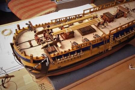
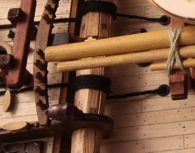
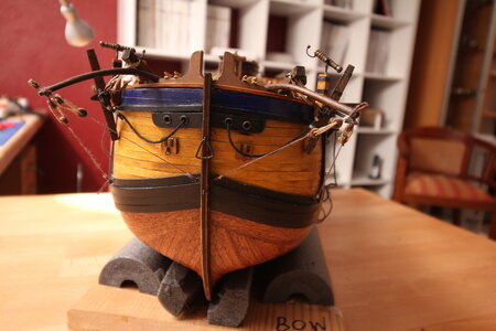
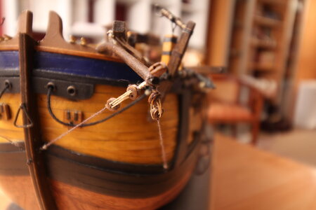
According to the books on maritme history, ships started using chains on their anchors around the mid 18th century. The Endeavour was built around this time, so the question was, use rope or chain to tie the anchors to the hull. I hope I have made the right choice using chain. The rope held by sticky tape in the image below is for the anchor bouy, which will be fixed with its bouy to the shroud later. I'll have to redo the deadeye at the port davit. I missed a hole!
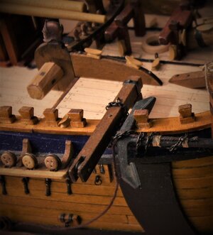
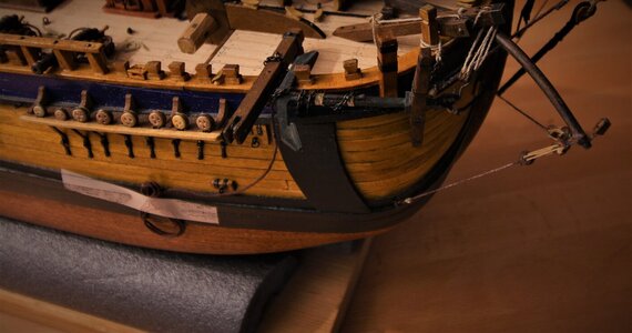
I have alread started work on the masts and bowsprit with boom and details will follow. I will also post some photos of the method I will use to taper the masts and yards.
The kit says to drill two holes in the deck for the anchor ropes. I found this to be non-satisfatory and so therefore I added a ring to each hole, as this would have been the case on the real ship. I am sure the anchor ropes would have chafed the wood if a strenghening ring had not been added. I also added rings to the holes in the bow where the anchor ropes exit the bow.


According to the books on maritme history, ships started using chains on their anchors around the mid 18th century. The Endeavour was built around this time, so the question was, use rope or chain to tie the anchors to the hull. I hope I have made the right choice using chain. The rope held by sticky tape in the image below is for the anchor bouy, which will be fixed with its bouy to the shroud later. I'll have to redo the deadeye at the port davit. I missed a hole!


I have alread started work on the masts and bowsprit with boom and details will follow. I will also post some photos of the method I will use to taper the masts and yards.
Last edited:
- Joined
- Dec 16, 2016
- Messages
- 1,178
- Points
- 493

Hi Dave, I have also had a bad experience with MSW site for posting my Amerigo Vespucci log here. The moderators were quite rude and posted lies about me to make it difficult for me to interact with members. I did get an apology of sorts. They slated this site and it’s moderators, they are blinded with their piracy policies, they have almost a vendetta going on, Our enemies are your enemies!Unfortunately I am banned from that site for building on this one, so I am not able to use the link. But thanks.
Enjoy the relaxed atmosphere of SOS. a more friendly forum
Ken
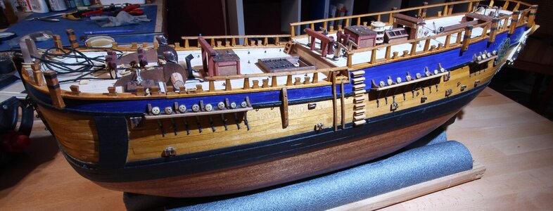
I would like to add a word here concerning the painting and finishing of my ship up to this point in the build.
I shied from paining the lower hull white, as depicted in many images of the Endeavour. I felt it a shame to cover such a large area of wood veneer planking with paint.
I read that the side inner walls to the deck under the railings were painted red to disguise any blood caused by injuries in battle. As far as I know, the Endeavour did not engage in battle during its life. I stand corrected if this fact is not true. I therefore chose not to paint those surfaces and left the wood a natural colour. The railings, the hull and smaller wooden parts were stained twice with diluted light oak. or with mahogony. Doing this once using middle oak would have been to dark. I will use this oak stain as well on all masts and yards. I carried out this operation before I attempted to glue parts with CA glue, as stain will not take to areas that have come in contact with CA glue. In between each staining operation I rubbed each surface down using a used piece of fine Scotch wool. Finally, I added clear satin water-based varnish to all surfaces, including the blocks, but not to the surfaces painted black or blue paint. This left a very slight sheen to the surfaces, without appearing unnatural for a sea-bound ship. Parts still stick to the varnished surfaces when using CA glue.
The paint itself came from Admiralty Colours. One can buy complete sets of this acrylic water-based paint for a designated ship.
All brass fittings, eyes, nails, hinges - lets say all metall work, were blackened using chemicals, as I felt the ship would look better not having shiny metal objects attached, apart from the ship's bell, that is. I rubbed the blackened surfaces with a lint-free cloth to give them the feel of used metal. I learnt a lesson here. Solder will not adhere to blackened (burnished?) surfaces. Molten solder just flows away from them, so I had to complete the plates for the dead-eyes before blackening them. Not a problem, though.
Last edited:
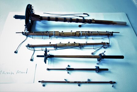
Masts and Yards.
The masts and yards are coming along well.
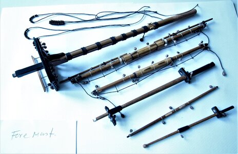
To taper them I used a cheapie wood turning lathe. The lathe had to be modified (extended), as it was too short to accommodate the fore and main masts. The lathe manufacturer supplied a set of brass bushes, each with a different ID and with a hole drilled through the end face to hold the end of the masts and yards at the tailstock.
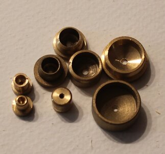
I used these as a template to drill a hole into the centre of the ends of the masts and yards, but not for the tapering step itself, otherwise it would have been necessary to cut off the remaing piece of wood located in the brass bush. I filled the hole in the end of the masts with wood filler and painted over. The holes in the end of the yards are needed for the stunsail hooks later.
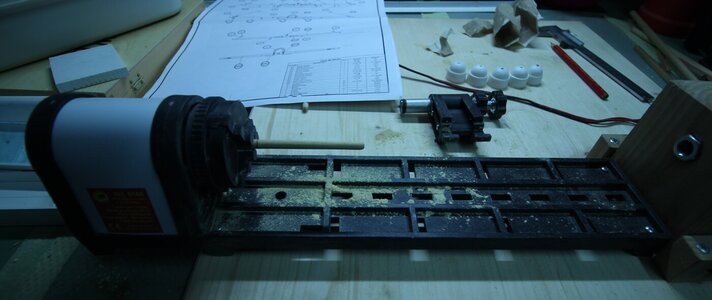
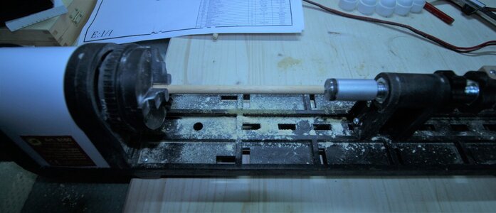
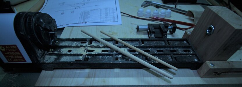
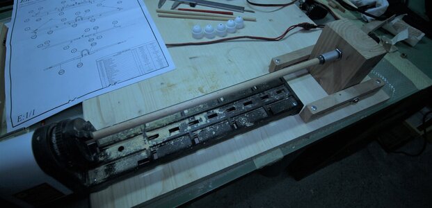
The batons assembled in the middle of the yards were attached using rubber ring seals to hold them into position, making any positional corrections necessary. I dropped some CA glue into the gaps between them and to the end of each piece. Staining was done beforehand and after sanding the edges.
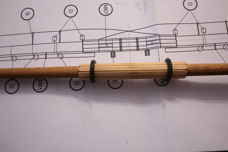
I repeated this procedure for the remaining yards.
The masts.
I have to admit I cheated with the square at the end of each mast. I manufactured the square seperately to the masts and attached each square to its appropriate mast after. To fix the squares to the masts I drilled a 2 mm hole into the end of each mast and square, about 7 mm deep, and using a 2mm rod of brass and CA glue, bonded the two together.
More to come as the yards are still work in progress.
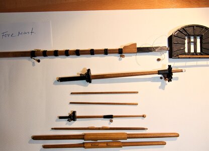
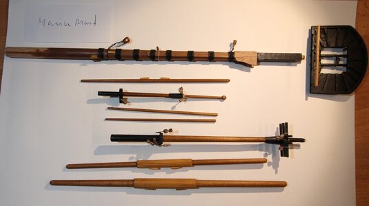
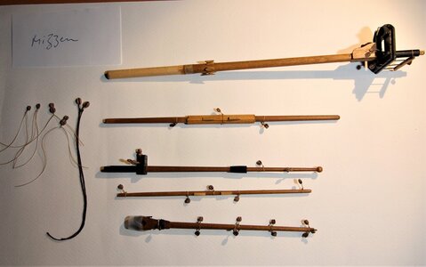
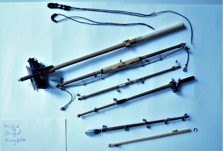
The Gaffel.
The kit manufacturer supplied a flat piece of cast aluminium for the jaw and I wasn't pleased with it. The radius was to big for the diameter of the mounting position on the mizzen and it didn't take the angle of the jaw to the mizzen into account, so it went into the bin. I created the angle of the radius by inserting a flat piece of wood into a drill vice at the required angle and using a flat drill at a high speed carefully driled through the wood. I drilled the two holes for the attaching thread and then proceeded to form the outer shape of the jaw.
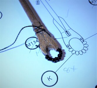
The masts and yards are coming along well.
To taper them I used a cheapie wood turning lathe. The lathe had to be modified (extended), as it was too short to accommodate the fore and main masts. The lathe manufacturer supplied a set of brass bushes, each with a different ID and with a hole drilled through the end face to hold the end of the masts and yards at the tailstock.

I used these as a template to drill a hole into the centre of the ends of the masts and yards, but not for the tapering step itself, otherwise it would have been necessary to cut off the remaing piece of wood located in the brass bush. I filled the hole in the end of the masts with wood filler and painted over. The holes in the end of the yards are needed for the stunsail hooks later.


The batons assembled in the middle of the yards were attached using rubber ring seals to hold them into position, making any positional corrections necessary. I dropped some CA glue into the gaps between them and to the end of each piece. Staining was done beforehand and after sanding the edges.

I repeated this procedure for the remaining yards.
The masts.
I have to admit I cheated with the square at the end of each mast. I manufactured the square seperately to the masts and attached each square to its appropriate mast after. To fix the squares to the masts I drilled a 2 mm hole into the end of each mast and square, about 7 mm deep, and using a 2mm rod of brass and CA glue, bonded the two together.
More to come as the yards are still work in progress.


The Gaffel.
The kit manufacturer supplied a flat piece of cast aluminium for the jaw and I wasn't pleased with it. The radius was to big for the diameter of the mounting position on the mizzen and it didn't take the angle of the jaw to the mizzen into account, so it went into the bin. I created the angle of the radius by inserting a flat piece of wood into a drill vice at the required angle and using a flat drill at a high speed carefully driled through the wood. I drilled the two holes for the attaching thread and then proceeded to form the outer shape of the jaw.

Last edited:
I’m banned there as well. SOS is the place.Hi Dave, I have also had a bad experience with MSW site for posting my Amerigo Vespucci log here. The moderators were quite rude and posted lies about me to make it difficult for me to interact with members. I did get an apology of sorts. They slated this site and it’s moderators, they are blinded with their piracy policies, they have almost a vendetta going on, Our enemies are your enemies!
Enjoy the relaxed atmosphere of SOS. a more friendly forum
Ken
Nice job indeed. The Endeavour was my first build ( Caldercraft), but was removed from a mentioned site I was part of when after a 'ethics' discussion I compaired the administrator with lines from The Holy Grail!. ( something along the lines of " I fart in your general direction.....). There are two colour options from Caldercraft ( White based- assumed as per others of the period ) and now a Brown base ( since some sailor notes discovered mentioned "Covered in the old brown stuff!"
As its your choice, no one will dispute natural wood or recommended paints. I painted mine as the being my first kit, planking was not spectacular. ( The bluff hull is a big challenge to any planker. ( Hence occre's decisison to block fill.
As its your choice, no one will dispute natural wood or recommended paints. I painted mine as the being my first kit, planking was not spectacular. ( The bluff hull is a big challenge to any planker. ( Hence occre's decisison to block fill.
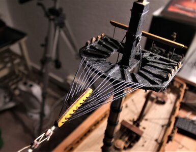
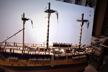
I have completed all masts and yards and commencing with the rigging. Photos to follow. I decided to do the crows feet and associate stays first and attach the gaffel before I tackle the shrouds. I ran into problems with the crows feet and the euphroes. Occre stipulated on the drawings to drill 10 holes into the tops for the fore and main masts, and 6 in the mizze. I am sure the number of holes incorrect, and I noticed this mistake after I having already glued the lower masts into the deck, so it would be difficult to remedy it. I shall leave them as the are.
The rigging plan from Occre is not a great help. No details for instance on how the standing rigging is attached to its appropriate fixing point, so I am using the AOS from Marquardt for reference.
II f anyone out there has a good rigging plan for the Endeavour, irrespective of the manufacturer, I would gladly appreciate a copy. Please send me a personal message if you have one spare.
Last edited:
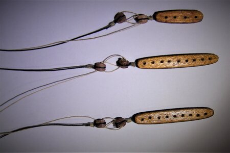
The lighting for the photos is not the best. I photographed the items under LED lighting. My mistake!
I bashed the stun sail stirrups and made these out of metall.
- Joined
- Apr 20, 2020
- Messages
- 6,239
- Points
- 738

Beautiful work, wish you and your family a happy new yearI remanufactured the euphroes to reflect the correct number of holes in each euphroe. The kit manufacturer called for 10 holes only in the tops
View attachment 279502
and assembled them onto the tops before I commenced with the shrouds.
View attachment 279503View attachment 279504


