Thank you very much, Christian!Happy birthday, Sergey
-

Win a Free Custom Engraved Brass Coin!!!
As a way to introduce our brass coins to the community, we will raffle off a free coin during the month of August. Follow link ABOVE for instructions for entering.
-

PRE-ORDER SHIPS IN SCALE TODAY!
The beloved Ships in Scale Magazine is back and charting a new course for 2026!
Discover new skills, new techniques, and new inspirations in every issue.
NOTE THAT OUR FIRST ISSUE WILL BE JAN/FEB 2026
- Home
- Forums
- Ships of Scale Group Builds and Projects
- HMS Alert 1777 1:48 PoF Group Build
- HMS Alert 1777 1:48 Group Build Logs
You are using an out of date browser. It may not display this or other websites correctly.
You should upgrade or use an alternative browser.
You should upgrade or use an alternative browser.
HMS Alert [1777] 1:48 POF by serikoff. (Two hulls: skeleton and fully rigged)
Friends, I am grateful to all of you for your congratulations!
I am very pleased with all your words and wishes.
And all of you are good, peace, health to you and your loved one!
4.7 Lower deck fixation.
Well, we continue the lower deck.
There is inconsistency and contradiction in anatomy.
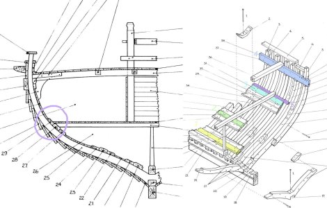
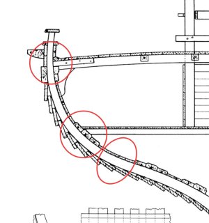
In one plan, the beam of the lower deck lies on the board, and in the background there is a bar that is interrupted (purple). I tried to study the question. And by all standards, beams should come into contact with frames, but not in all cases! At very lower levels in small and medium-sized ships, where the angle of the frame at such an angle that it tends to horizontal, the beams could lie directly on the power boards of the inner skin.
In Alerta, this can be applied to the rear beams on the lower deck (where the powder magazine was). This level is slightly below the main level of the lower deck.
But on the main part of the lower deck, a little different. Since the frame also has a corner with a frame that is not vertical, the entire beam is wide enough to interrupt the skin boards so that we make the side more fragile. Therefore, it is more logical that only part of the beam lies on the frame (and a small board is interrupted. In this case, this is shown in the right plan, purple board). And part of the beams lay on the upper power board. Thus, beams touched the frames, but did not greatly interrupt the power boards.
That's why I did it.

On the lower level of the lower deck, I made a small gap between the beam and the frame, simulating the location under the beam of the board.

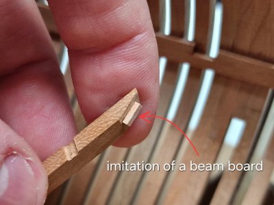
And on the upper level of the lower deck - it will be a little different, but more on that later. In the meantime, what it looks like.
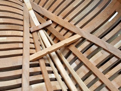
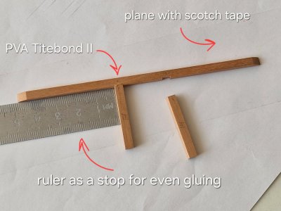
To glue the transverse beams, you need to make suitable grooves and use a ruler to glue them at an angle of 90 degrees.
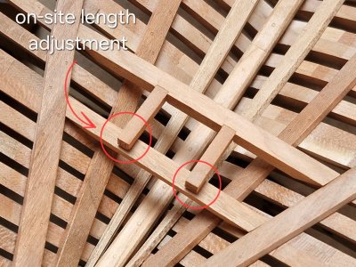
Then I tried everything on in place and clipped to the length I needed.
At the inspection, Nelson said that everything is ok
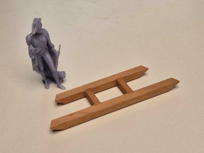
Without glue, I tried everything together.
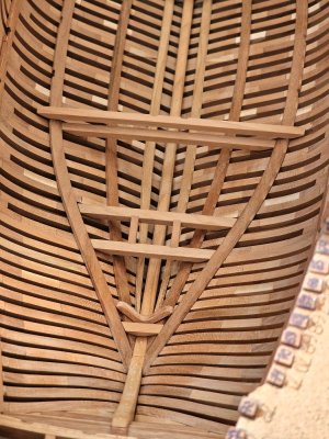
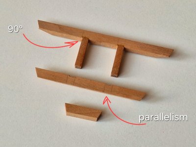
By the way, how the perpendicularity and parallelism of beams is created, everything is simple.
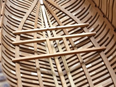
And here's another fragment without glue is approximate in place.

As you can see, beams do not reach the frames as a whole, but I did this to simplify the fit. Only the upper part will be visible and will be in the air (there should be a board). And the area that should touch the frame will be closed by an interrupted board (bar, which is purple in the diagram).
I don't know if this was possible, most likely not (I haven't seen this in anatomies), I'm talking about the fact that beams did not coincide with frames. That is, beams should not logically be in the space between the frames, but in the kit so. I do this because I do not want to deal with fixing all this, it will take a lot of time. But if so, then this is a big miscalculation of the manufacturer, but as it is. continue on.
...
I am very pleased with all your words and wishes.
And all of you are good, peace, health to you and your loved one!
4.7 Lower deck fixation.
Well, we continue the lower deck.
There is inconsistency and contradiction in anatomy.

In one plan, the beam of the lower deck lies on the board, and in the background there is a bar that is interrupted (purple). I tried to study the question. And by all standards, beams should come into contact with frames, but not in all cases! At very lower levels in small and medium-sized ships, where the angle of the frame at such an angle that it tends to horizontal, the beams could lie directly on the power boards of the inner skin.
In Alerta, this can be applied to the rear beams on the lower deck (where the powder magazine was). This level is slightly below the main level of the lower deck.
But on the main part of the lower deck, a little different. Since the frame also has a corner with a frame that is not vertical, the entire beam is wide enough to interrupt the skin boards so that we make the side more fragile. Therefore, it is more logical that only part of the beam lies on the frame (and a small board is interrupted. In this case, this is shown in the right plan, purple board). And part of the beams lay on the upper power board. Thus, beams touched the frames, but did not greatly interrupt the power boards.
That's why I did it.

On the lower level of the lower deck, I made a small gap between the beam and the frame, simulating the location under the beam of the board.


And on the upper level of the lower deck - it will be a little different, but more on that later. In the meantime, what it looks like.

To glue the transverse beams, you need to make suitable grooves and use a ruler to glue them at an angle of 90 degrees.

Then I tried everything on in place and clipped to the length I needed.

At the inspection, Nelson said that everything is ok

Without glue, I tried everything together.

By the way, how the perpendicularity and parallelism of beams is created, everything is simple.

And here's another fragment without glue is approximate in place.

As you can see, beams do not reach the frames as a whole, but I did this to simplify the fit. Only the upper part will be visible and will be in the air (there should be a board). And the area that should touch the frame will be closed by an interrupted board (bar, which is purple in the diagram).
I don't know if this was possible, most likely not (I haven't seen this in anatomies), I'm talking about the fact that beams did not coincide with frames. That is, beams should not logically be in the space between the frames, but in the kit so. I do this because I do not want to deal with fixing all this, it will take a lot of time. But if so, then this is a big miscalculation of the manufacturer, but as it is. continue on.

...
Last edited:
Дякую!!! Allan.
- Joined
- Mar 1, 2022
- Messages
- 679
- Points
- 308

That's a good point. Leaving a gap between the omitted celing and some of the inner structures, as knees or floor timbers, is absolutely right, but not (IMHO...) between beames and frames.
Antscherl's Hoy practicum seems to suggest they were rather mortised into the spirkettings and bolted directly to the main frame.
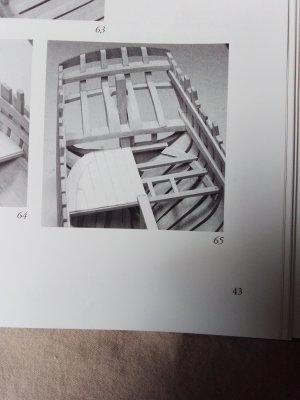
Antscherl's Hoy practicum seems to suggest they were rather mortised into the spirkettings and bolted directly to the main frame.


You are right! But in the kit the manufacturer made it so that most of the beams do not fall on the frames and according to the city then they are fixed to the air. If you miss this point and trust the anatomy (in the image on the left), then you can see that the beams lie directly on the load board with their entire beveled plane. And here either the author of the anatomy is mistaken or on small ships on the deck above the hold it was possible. I understand that this is not logical ... but based on the fact that not all beams fall on the frames, the logic in fastening to the load board does not seem so wrong. Since the load board is 2-3 times thicker than usual, what could withstand the beams of the deck above the hold, where there were no guns or cargo, as on a cargo ship.That's a good point. Leaving a gap between the omitted celing and some of the inner structures, as knees or floor timbers, is absolutely right, but not (IMHO...) between beames and frames.
Antscherl's Hoy practicum seems to suggest they were rather mortised into the spirkettings and bolted directly to the main frame.
View attachment 523884
View attachment 523885
View attachment 523887
- Joined
- Mar 1, 2022
- Messages
- 679
- Points
- 308

You are right! But in the kit the manufacturer made it so that most of the beams do not fall on the frames and according to the city then they are fixed to the air. If you miss this point and trust the anatomy (in the image on the left), then you can see that the beams lie directly on the load board with their entire beveled plane. And here either the author of the anatomy is mistaken or on small ships on the deck above the hold it was possible. I understand that this is not logical ... but based on the fact that not all beams fall on the frames, the logic in fastening to the load board does not seem so wrong. Since the load board is 2-3 times thicker than usual, what could withstand the beams of the deck above the hold, where there were no guns or cargo, as on a cargo ship.
Sorry, now I got it. In that case you are totally right. Anyway I agree no real shipwright of the XVIII century could be so dumb to nail a beam right into the celling alone. Smart recovery, though! Cheers
Happy birthday Sergey!
Bill
Bill
Good evening Sergey. Firstly a big happy birthday for yesterday. I hope you had a wonderful day.Friends, I am grateful to all of you for your congratulations!
I am very pleased with all your words and wishes.
And all of you are good, peace, health to you and your loved one!
Well, we continue the lower deck.
There is inconsistency and contradiction in anatomy.
View attachment 523870
In one plan, the beam of the lower deck lies on the board, and in the background there is a bar that is interrupted (purple). I tried to study the question. And by all standards, beams should come into contact with frames, but not in all cases! At very lower levels in small and medium-sized ships, where the angle of the frame at such an angle that it tends to horizontal, the beams could lie directly on the power boards of the inner skin.
In Alerta, this can be applied to the rear beams on the lower deck (where the powder magazine was). This level is slightly below the main level of the lower deck.
But on the main part of the lower deck, a little different. Since the frame also has a corner with a frame that is not vertical, the entire beam is wide enough to interrupt the skin boards so that we make the side more fragile. Therefore, it is more logical that only part of the beam lies on the frame (and a small board is interrupted. In this case, this is shown in the right plan, purple board). And part of the beams lay on the upper power board. Thus, beams touched the frames, but did not greatly interrupt the power boards.
That's why I did it.
View attachment 523871
On the lower level of the lower deck, I made a small gap between the beam and the frame, simulating the location under the beam of the board.
View attachment 523872
View attachment 523873
And on the upper level of the lower deck - it will be a little different, but more on that later. In the meantime, what it looks like.
View attachment 523874
To glue the transverse beams, you need to make suitable grooves and use a ruler to glue them at an angle of 90 degrees.
View attachment 523875
Then I tried everything on in place and clipped to the length I needed.
View attachment 523876
At the inspection, Nelson said that everything is ok
View attachment 523877
Without glue, I tried everything together.
View attachment 523878
By the way, how the perpendicularity and parallelism of beams is created, everything is simple.
View attachment 523879
And here's another fragment without glue is approximate in place.
View attachment 523880
As you can see, beams do not reach the frames as a whole, but I did this to simplify the fit. Only the upper part will be visible and will be in the air (there should be a board). And the area that should touch the frame will be closed by an interrupted board (bar, which is purple in the diagram).
I don't know if this was possible, most likely not (I haven't seen this in anatomies), I'm talking about the fact that beams did not coincide with frames. That is, beams should not logically be in the space between the frames, but in the kit so. I do this because I do not want to deal with fixing all this, it will take a lot of time. But if so, then this is a big miscalculation of the manufacturer, but as it is. continue on.
View attachment 523881
...
Wow. What brilliant modelling. Thank you so much for sharing in detail your process. I am going to go back and re read some sections- I love the way you sand and polish the wood it gives a wonderful finish. Cheers Grant
But unfortunately I can't say for sure that my version is reliable, but logically and in my opinion it is quite possible. I have already done so and there is no way backSorry, now I got it. In that case you are totally right. Anyway I agree no real shipwright of the XVIII century could be so dumb to nail a beam right into the celling alone. Smart recovery, though! Cheers

Thanks a lot, BillHappy birthday Sergey!
Bill
Thanks for the congratulations, Great! Yes, it was a great day. And thanks for the praise of my review. I hope I am doing everything right and not misinforming anyone, but I try to make the work at least beautiful.Good evening Sergey. Firstly a big happy birthday for yesterday. I hope you had a wonderful day.
Wow. What brilliant modelling. Thank you so much for sharing in detail your process. I am going to go back and re read some sections- I love the way you sand and polish the wood it gives a wonderful finish. Cheers Grant
Thank you for your congratulations and your assessment of my review.Happy belated birthday! Your build is looking very good!
- Joined
- Dec 5, 2022
- Messages
- 1,109
- Points
- 443

Hello Sergey.
Firstly, happy birthday yesterday. I hope you had a great day and were able to enjoy it with your loved ones.
Your model is really beautiful and the way you worked the wood is world class. May I ask how long you spend on your model each day? What a brilliant model! I really like the way you build and explain things to us. I can only learn from you.
I'm always happy to see your progress.
Best regards
Günther

Thank you very much for the congratulations and kind words about my build. Most likely my answer got lost. To your question, how long have I been working on the ship, and you can read it at this link.Hello Sergey.
Firstly, happy birthday yesterday. I hope you had a great day and were able to enjoy it with your loved ones.
Your model is really beautiful and the way you worked the wood is world class. May I ask how long you spend on your model each day? What a brilliant model! I really like the way you build and explain things to us. I can only learn from you.
I'm always happy to see your progress.
Best regards
Günther
Dziękuję bardzo za gratulacje, Mirek!Witaj
Wszystkiego najlepszego Sergey spóźnione ale szczere życzenia urodzinowe. Pozdrawiam Mirek
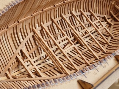
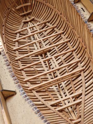
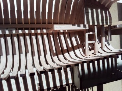
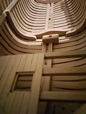
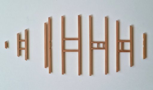
I continue to prepare the lower deck, moving further along the beams.
The knot at the mast attachment point is slightly more complicated. First, you need to remove the rounded corners from the cutter (making them straight) and prepare a thin bar with a protrusion.
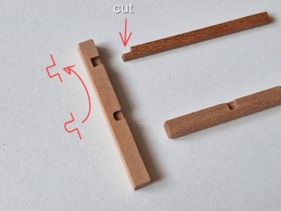
Then I glued one joint on the PVA...
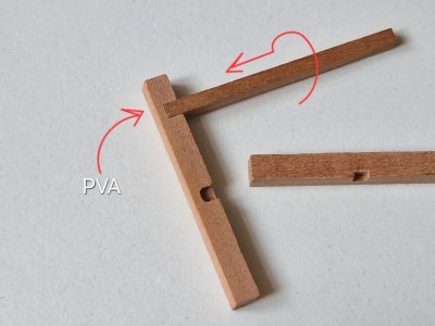
(this connection forms a lock and here the correct geometry and perpendicularity are very important so that there are no gaps).
... and then glued the second connection and it was necessary to cut off the excess, calculating the distance between the parts.
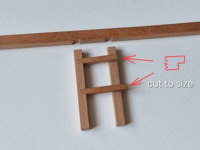
The finished element is first fitted and glued to one beam...
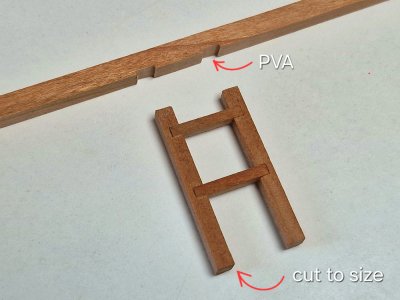
... and then it is adjusted to the distance between the beams, cuted and glued to the second beam. After that, the fit is checked without glue.

Thus, I got three paired designs of beams of the middle segment of the deck.
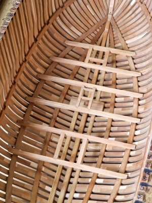
Now, all beams with all horizontal elements are ready!

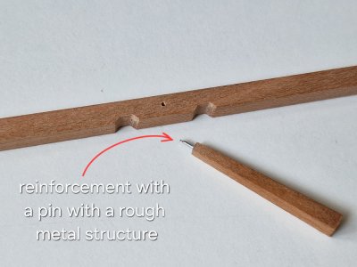
Now, only vertical support racks remain, which were fixed to the center of the beams.
To keep these racks and not fall off, I reinforced the glue seam with a steel pin (with a rough metal texture). And he fixed all this on CA gel.

Then he adjusted the height in place by trimming and checking many times until he achieved a perfect landing.
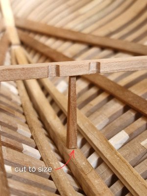
As a result, I got this.
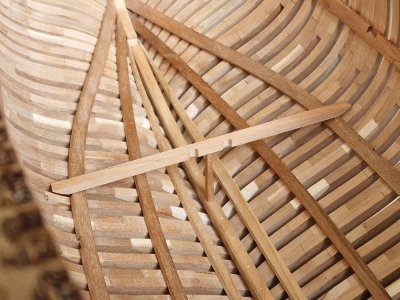
There are similar actions with paired beams.
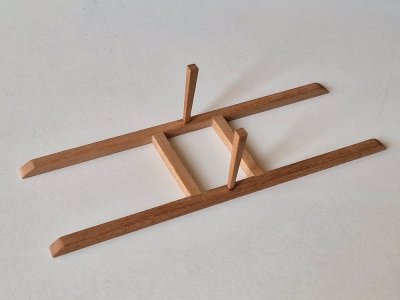
Only kuting in place is harder.


The final fragment of the thaw was a beam, which served to strengthen the connection of beams under the cauldron where food was prepared.
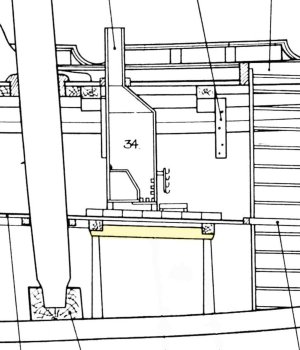
In the drawings, it was slightly different from what the manufacturer offers, I repeated the anatomy option.

I finally checked everything without glue and it will be possible to prepare everything to glue to the ship's hull.
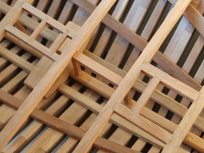
Tomorrow, if everything goes well - first I stick knits, and then all the beams of the lower deck...
P.S. Oh yes, you need not forget the imitation of bolts on all beam connections and elements that were attached to them.
The knot at the mast attachment point is slightly more complicated. First, you need to remove the rounded corners from the cutter (making them straight) and prepare a thin bar with a protrusion.

Then I glued one joint on the PVA...

(this connection forms a lock and here the correct geometry and perpendicularity are very important so that there are no gaps).
... and then glued the second connection and it was necessary to cut off the excess, calculating the distance between the parts.

The finished element is first fitted and glued to one beam...

... and then it is adjusted to the distance between the beams, cuted and glued to the second beam. After that, the fit is checked without glue.

Thus, I got three paired designs of beams of the middle segment of the deck.

Now, all beams with all horizontal elements are ready!


Now, only vertical support racks remain, which were fixed to the center of the beams.
To keep these racks and not fall off, I reinforced the glue seam with a steel pin (with a rough metal texture). And he fixed all this on CA gel.


Then he adjusted the height in place by trimming and checking many times until he achieved a perfect landing.

As a result, I got this.

There are similar actions with paired beams.

Only kuting in place is harder.


The final fragment of the thaw was a beam, which served to strengthen the connection of beams under the cauldron where food was prepared.

In the drawings, it was slightly different from what the manufacturer offers, I repeated the anatomy option.

I finally checked everything without glue and it will be possible to prepare everything to glue to the ship's hull.

Tomorrow, if everything goes well - first I stick knits, and then all the beams of the lower deck...
P.S. Oh yes, you need not forget the imitation of bolts on all beam connections and elements that were attached to them.
Last edited:
- Joined
- Mar 1, 2022
- Messages
- 679
- Points
- 308

Incredibly well executed, I'm speechless...
Thanks to such comments, as @Albert Mary wrote the motivation to show you in even more detail that I am building here.
So, we continue, or rather, we are finishing work on the lower deck, today it will be interesting...
And first, let's close the issue with the knees. I made imitation bolts on them and pasted them into the appropriate places. Earlier I showed a diagram of bolts on knees, nothing complicated here...
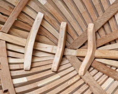
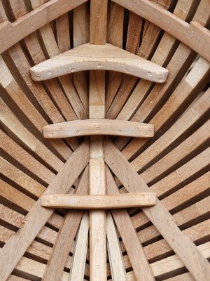
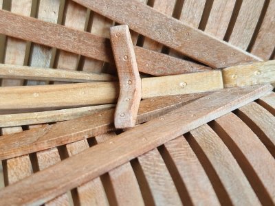
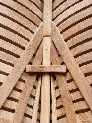
Then he made imitation bolts on beams and Carlings (elings).
Connection between beams and Carlings (elings) took place by cutting in and fastening with two bolts diagonally. The imitation was carried out, as previously described.
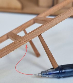
The connection between the beams and the hull did not take place directly to the frames, but to the power rail using two bolts, also placed diagonally.


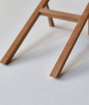
The connection between the Carlings and Ledges (slats thinner) took place by two methods. Or the same as the previous ones...

... or by another kind of cutting-in and glowing from above.
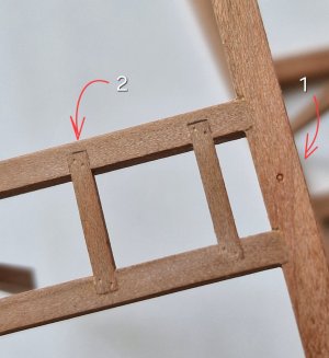
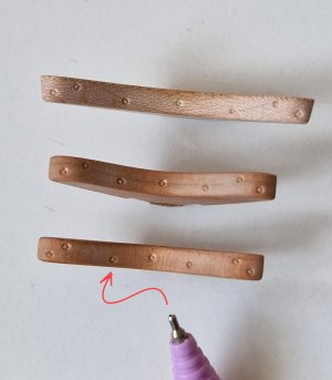
I made an imitation with a needle and then rubbed a little with fine sandpaper so that the dust clogged the holes and when applying oil there would be a round trace (2 in the photo on top, and what is marked 1 is an imitation of a bolt that fixes the support to the beam).
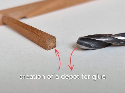
For this support, I make a drill (by 4) a small recess to create a place for glue.
And the only detail that I did not stick was the front beam. Beams, which holds the element from below, which passes through the entire hull of the ship and is fixed on the upper deck. Therefore, I will fix both beams at the same time in order to accurately determine the grooves for fixing Pawl bitt pin.

I glued the rest of the elements according to this scheme.
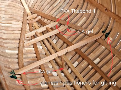
For convenience, so that the beams do not move during fixation, I locked the beams on the sides with ordinary clerical clamps. It's convenient, I positioned bbms without glue, squeezing it on the sides, and then I just took it out, brought in the glue and put the beam in the right place in one motion and pressed it, that's all. Very simple.
Now, a little fixation slideshow... (by tradition).
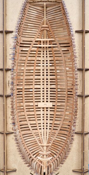
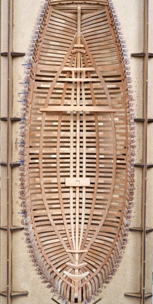
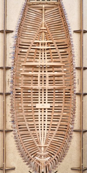
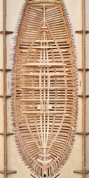
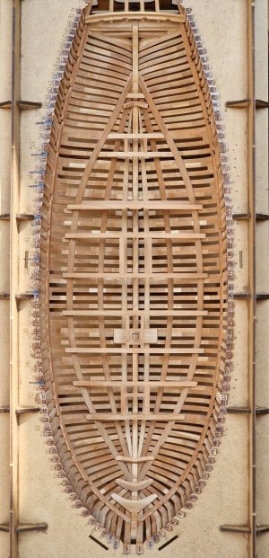
A little later I will post more macro photos from different angles.
So, we continue, or rather, we are finishing work on the lower deck, today it will be interesting...
And first, let's close the issue with the knees. I made imitation bolts on them and pasted them into the appropriate places. Earlier I showed a diagram of bolts on knees, nothing complicated here...


Then he made imitation bolts on beams and Carlings (elings).
Connection between beams and Carlings (elings) took place by cutting in and fastening with two bolts diagonally. The imitation was carried out, as previously described.

The connection between the beams and the hull did not take place directly to the frames, but to the power rail using two bolts, also placed diagonally.


The connection between the Carlings and Ledges (slats thinner) took place by two methods. Or the same as the previous ones...

... or by another kind of cutting-in and glowing from above.

I made an imitation with a needle and then rubbed a little with fine sandpaper so that the dust clogged the holes and when applying oil there would be a round trace (2 in the photo on top, and what is marked 1 is an imitation of a bolt that fixes the support to the beam).
For this support, I make a drill (by 4) a small recess to create a place for glue.

And the only detail that I did not stick was the front beam. Beams, which holds the element from below, which passes through the entire hull of the ship and is fixed on the upper deck. Therefore, I will fix both beams at the same time in order to accurately determine the grooves for fixing Pawl bitt pin.

I glued the rest of the elements according to this scheme.

For convenience, so that the beams do not move during fixation, I locked the beams on the sides with ordinary clerical clamps. It's convenient, I positioned bbms without glue, squeezing it on the sides, and then I just took it out, brought in the glue and put the beam in the right place in one motion and pressed it, that's all. Very simple.
Now, a little fixation slideshow... (by tradition).


A little later I will post more macro photos from different angles.
- Joined
- Mar 1, 2022
- Messages
- 679
- Points
- 308

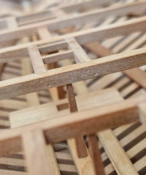
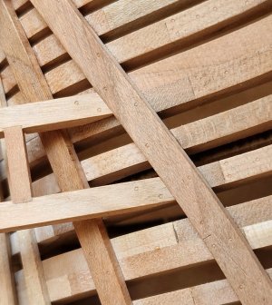
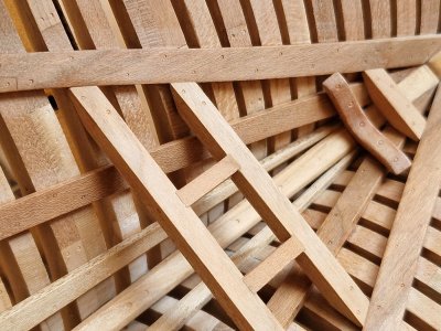
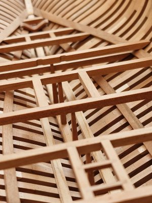
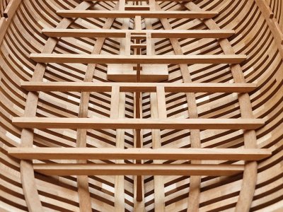
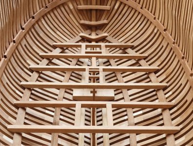
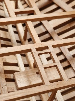
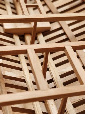
She's coming along so nicely. I like your "faux nailing work" as well. I read that some fear the moment you would go with oil or other finishing treatment, but in that case, untill the moment you won't be able to reach the hold due to the upper structures, you can dye nail heads in black. Cheers!... continuation of the previous post, some macro and beautiful angles...
View attachment 524627
View attachment 524628
View attachment 524629
View attachment 524630
View attachment 524631
View attachment 524632
View attachment 524633
View attachment 524634
View attachment 524635
View attachment 524636
View attachment 524637
View attachment 524638
View attachment 524639
View attachment 524640
View attachment 524641
On this I would like to say that with the lower deck everything... but there are still two stairs left... I have already started doing them, I will show the result soon...


