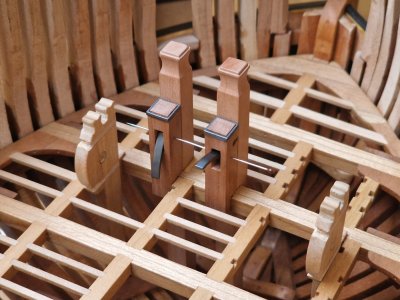
Outstanding ! Truly a museum quality piece of art !

 |
The beloved Ships in Scale Magazine is back and charting a new course for 2026! Discover new skills, new techniques, and new inspirations in every issue. NOTE THAT OUR NEXT ISSUE WILL BE July/August 2026 |
|
 |
As a way to introduce our brass coins to the community, we will raffle off a free coin during the month of August. Follow link ABOVE for instructions for entering. |
|

Wow….. was für ein schönes Bauteil. Ein Modell im Modell. Du kommst deinem angestrebten „Museumsmodell-Stil - Modell“ immer näher. Ein wunderschönes Detail, das Du hier wieder erstellt und gezeigt hast. Beeindruckend. Ich liebe deinen Baustil. Wie Du alle Schritte dazu zeigst und dokumentierst. Das „Eine“ ist das Ergebnis der Erstellung einzelner Schritte. Aber das „Andere“ und meiner Meinung nach das „Wichtigere“ ist zu zeigen, wie man dorthin gekangt, wie es erstellt und umgesetzt wird. Das zeigt Du absolut ausgezeichnet. Ganz großes Kino. Vielen Dank für den dazu notwendigen Aufwand und immer wieder das Zeigen dazu. Das wird ein wunderschönes und qualitativ sehr hochwertiges Modell. Danke!* Da ich keine Fotos hochladen kann, füge ich vorübergehend Bilder aus einer anderen Quelle bei und werde sie ersetzen, sobald es möglich ist, hier Fotos hochzuladen.
Kapitel 26. An Deck (Teil 4)
8/
Ankerwinde. (Schlussfolgerung)
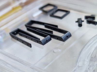
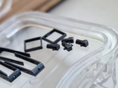
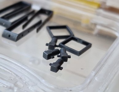
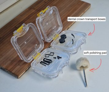
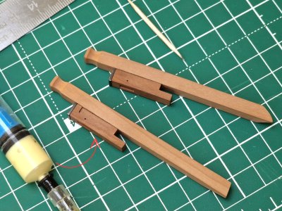
Ich habe die Griffe mit Fünf-Minuten-Epoxidharz festgeklebt, was sich sehr gut eignet, um den richtigen Winkel und die richtige Position festzulegen. Die Haltestifte habe ich mit Titebond II verklebt. Dazu habe ich den Klebstoff mit einem Spritze in das Loch injiziert, bevor ich den Stift eingesetzt und den Überschuss abgewischt habe. Diese Methode ist praktisch, weil sie ein sauberes Auftragen ermöglicht. Da dieses Bauteil nicht verschleißend ist, ist diese Art der Verklebung ausreichend und erleichtert zudem zukünftige Reparaturen. Auf der gegenüberliegenden Seite habe ich eine 0,6-mm-Schraube eingesetzt.
Ich habe außerdem Bolzen (aus 0,5 mm Messingdraht) angebracht. Da der Schiffsrumpf keine Deckplanken hat – das Knie aber am Deck anliegt – habe ich die Bolzen so positioniert, dass sie sichtbar bleiben; Sie sind nicht nur wegen der fehlenden Planken sichtbar, sondern auf einer Seite auch, weil zwischen den Klinkern keine Querverstrebungen vorhanden sind.


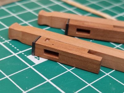
Und hier ist das Ergebnis… Ich habe es endlich geschafft, eine gute Beleuchtung einzurichten, und die Fotos sind ziemlich gut geworden.


Auf dem oberen Foto kann man deutlich sehen, wie die Griffe genau dort glänzen, wo ich freiliegendes Metall simuliert habe – das Ergebnis der ständigen Reibung durch das Drehen der Hände.
Damit wäre die Sache mit diesen Komponenten erledigt; Als nächstes kommt der Verankerungsmechanismus... und da wird es interessanter – und weitaus komplexer.



Congratulations with this now ‘over the year’ project, Sergey.A moment for some useless statistics...
- The project began in mid-March 2025. That was a year and a half ago.
- Today marks exactly the 365th day of work on the two models... which means I’ve spent two out of every three days over the past year and a half working on them.
- Considering I spent 5–6 hours a day on it, that adds up to over 2,000–2,200 hours of work.
- I’ve completed the 26th installment of the build log; each part contains 120–130 photos, bringing the total count to over 3,000 images.
- Hull #1 currently consists of 1,280 parts, plus 200 clinker planking bolts and 800 wooden pegs.
- Hull #2 currently consists of 905 parts, plus 1,914 clinker planking bolts and 2,328 wooden pegs.
This project has been the best therapist for me given the current situation—with my country in the midst of war. It is precisely this project that keeps my mental health intact.
Thank you to everyone who supports me! Thanks for your comments—especially to the most dedicated fans who leave feedback on almost every post. And thanks to everyone who leaves reactions; it really means a lot! I’m glad you enjoy the build log and that I can be of help to you.
Show must go on, so... let’s keep going!!!
View attachment 637133
Es ist schön, dass der Bau des Modells Dich von dem unsagbaren Leid des Krieges ablenkt. Es ist hier im Forum eine ganz spannende Geschichte, deinem Modell zu folgen und zu sehen, wie es immer weiter entsteht. Ich freue mich auf noch viele weitere Berichte dazu. Toll auch deine kontinuierliche Ausdauer mit einer stetig wachsenden Qualität. Es ist eine große Freude den Bericht immer und immer wieder zu studieren. Paß auf Dich auf und bleibe gesund.Ein Moment für ein paar nutzlose Statistiken...
Das Projekt begann Mitte März 2025. Das ist nun anderthalb Jahre her.
- Heute ist genau der 365. Arbeitstag an den beiden Modellen... das heißt, ich habe in den letzten anderthalb Jahren zwei von drei Tagen daran gearbeitet.
Wenn man bedenkt, dass ich täglich 5–6 Stunden dafür aufgewendet habe, summiert sich das auf über 2.000–2.200 Arbeitsstunden .
- Ich habe den 26. Teil des Bautagebuchs fertiggestellt; Jeder Teil enthält 120–130 Fotos, sodass die Gesamtzahl über 3.000 Bilder beträgt.
- Rumpf Nr. 1 besteht derzeit aus 1.280 Teilen, zuzüglich 200 Klinkerplankenbolzen und 800 Holznägeln.
- Rumpf Nr. 2 besteht derzeit aus 905 Teilen, zuzüglich 1.914 Klinkerplankenbolzen und 2.328 Holznägeln.
Dieses Projekt war in der aktuellen Situation – mein Land befindet sich mitten im Krieg – für mich der beste Therapeuten. Es ist genau dieses Projekt, das meine psychische Gesundheit erhält.
Vielen Dank an alle, die mich unterstützen! Danke für eure Kommentare – besonders an die treuesten Fans, die fast jeden Beitrag kommentieren. Und danke an alle, die reagieren; das bedeutet mir wirklich viel! Ich freue mich, dass euch der Baubericht gefällt und ich euch helfen konnte.
Die Show muss weitergehen, also... lasst uns weitermachen!!!
View attachment 637133

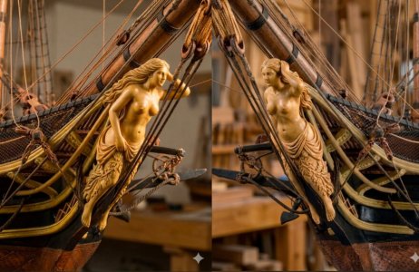
Thanks for the compliment on the figurehead.The figurehead turned out good, with very good looking details. Could you write some more theory about polishing with steel wool- what is the purpose of it?
Sehr interessant. Was alles möglich ist. Beeindruckend!Freunde, @Charlie1805, @Corsair, @Peter Voogt, @Joseph PL und @GrantTyler, vielen Dank für eure freundlichen Worte; es ist mir eine wahre Freude, sie zu lesen!
* Ich habe die folgenden Informationen aus einem anderen meiner Threads erneut veröffentlicht, damit sie auch hier verfügbar sind; ich bin wirklich erstaunt darüber, was heutzutage mit KI möglich ist.
Dank eines Forumsmitglieds @g8rfan99 besitze ich nun ein 3D-Modell der Galionsfigur der Brigg *Le Faune* – ein Projekt, das ich vielleicht in Angriff nehmen werde, sobald ich alle meine aktuellen Projekte abgeschlossen habe. Die Figur ist in unglaublich hoher Auflösung gerendert und besticht durch hervorragende Details.


Ich habe die Position berechnet, und sie ist perfekt für dieses Modell. Anders als die „Entenfigur“ auf *Le Cygne* ist diese Form nicht nur schön, sondern benötigt auch nicht die Art von Locken am Oberkopf, die man über dem Schwan sieht; stattdessen liegt das Haar des Mädchens ordentlich in diesem Bereich.


Die Figur beeinträchtigt weder die Takelage noch den Bugspriet und ergänzt den Bug perfekt. Kurz gesagt, sie gefällt mir sehr gut. Und sollte ich nach meinen aktuellen Projekten doch noch ein weiteres Modell bauen, wird es definitiv die *Le Faune* sein, basierend auf der Monografie des Schwesterschiffs der Brigg *Le Cygne*.
Nur zur Erinnerung: Diese 3D-Figur wurde mit dem 3D-KI-Tool MeshyAI erstellt und aus einem Bild generiert, das eine andere KI – Gemini – anhand meiner Beschreibung erstellt hat… es ist absolut umwerfend… zu denken, dass so etwas heutzutage möglich ist!
View attachment 637484
Es ergibt sich eine fantastische, gleichmäßige Oberfläche. Deine Großaufnahmen zeigen dies beeindruckend.Danke für das Kompliment zur Galionsfigur.
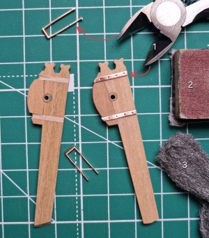
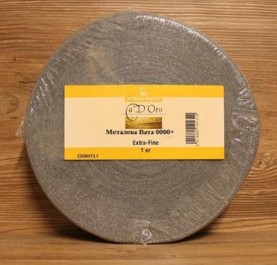
Zu Ihrer Frage: Ich verwende die Stahlwolle, die auf dem Foto zu sehen ist. Meistens nutze ich die Körnung 000. Körnung 00 ist für die erste Reinigung und das Schleifen, Körnungen ab 0000 für das Feinpolieren, aber 000 ist meine Standardkörnung. Ich kaufe sie meterweise, da eine große Spule teuer ist und ich nicht so viel brauche. Und vor allem – wofür ist sie gut? Erstens runden Sie Ecken und Kanten leicht ab – etwas, das mit Schleifpapier schwer vorhersehbar zu erreichen ist. Zweitens entfernten sie die Kratzer, die Schleifpapier hinterließ. Ja, das geht auch mit feinem Schleifpapier, aber das funktioniert am besten auf flachen Oberflächen; Bei komplexen Formen kann es schwierig sein. Und drittens sehen Sie mit Stahlwolle behandelte Teile edel aus – es gibt einfach keinen Vergleich zu unbehandelten Teilen. Nach dem Einölen fühlt sich die Oberfläche samtig an und sieht hervorragend aus. Man sollte es aber nicht übertreiben. Eine zu stark polierte Oberfläche (insbesondere durch die Verwendung von Stahlwolle der Körnung 0000+) wird sehr glänzend, und das Öl verstärkt diesen Effekt. Daher ist etwas Experimentieren nötig. Dennoch gebe ich jedem einzelnen Teil den letzten Schliff mit Stahlwolle der Körnung 000.
View attachment 637540


Do you use it on wood too or only metal parts?Thanks for the compliment on the figurehead.
Regarding your question: I use the type of steel wool shown in the photo. I mostly use grade 000; grade 00 is for initial cleaning and sanding, and grades 0000+ are for spot polishing, but 000 is my go-to grade. I buy it by the meter because a huge spool is expensive and I don't need that much. And most importantly—what is it for? First, it slightly rounds off corners and edges—something that is hard to do predictably with sandpaper. Second, it removes the scratches left by sandpaper. Yes, you can do that by stepping down through abrasive grits, but that works best on flat surfaces; it can be difficult with complex shapes. And third, parts treated with steel wool look rich—there is simply no comparison to parts that haven't been treated this way. After applying oil, the surface has a velvety feel and looks excellent. However, you shouldn't overdo it. A surface that is too highly polished (especially after using 0000+) becomes very shiny, and the oil amplifies that effect, so you need to experiment a bit. That said, I do give the final finish to absolutely every part using grade 000 steel wool.
View attachment 637540
Serikoff, entschuldige bitte daß ich mit meiner Antwort vorgreiffe. Bei unbehandeltem Holz unbedingt „Proben / Test“ durchführen, da einige Hölzer „Gerbsäure“ enthalten und dies zu blauen Verfärbungen am Holz führen könnte > klassisch wäre dafür „Eiche“ ( wird allerdings kaum im Modellbau 1:48 verwendet) Dies nur als kleiner HinweisVerwenden Sie es auch für Holz oder nur für Metallteile?
It can be used on most woods as well as metals. Consider it as something finer than the sand paper you use.Do you use it on wood too or only metal parts?

I use steel wool for both wood and copper. In the review, I often showed photos of the cotton wool next to the wood I was treating. I also use it on plastic; however, since I’ve only worked with very small parts so far, I haven’t used it much yet—but in the future, I’ll show what can be done with steel wool on plastic.Do you use it on wood too or only metal parts?
Manchmal kann sich Stahlwolle in den großen Poren des Holzes verfangen und rosten, dies trifft jedoch nur auf bestimmte Holzarten zu, die in unserem Hobby üblicherweise nicht verwendet werden.Bei unbehandeltem Holz unbedingt „Proben / Test“ durchführen, da manche Hölzer „Gerbsäure“ enthalten und dies zu blauen Verfärbungen am Holz führen könnte > klassisch wäre dafür „Eiche“ ( wird allerdings kaum im Modellbau 1:48 verwendet) Dies nur als kleiner Hinweis

You are absolutely right.It can be used on most woods as well as metals. Consider it as something finer than the sand paper you use.
Sorry Serikoff, I hope I didn't step on your toes.

Absolutely beautiful and very well thought out !Chapter 27. On the Decks (Part 5)
Аnchоr Windlass.
1/
View attachment 638445
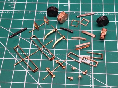
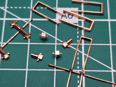
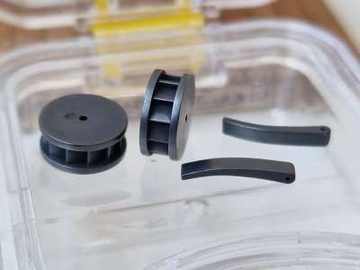
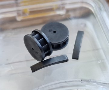
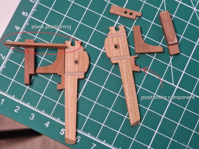
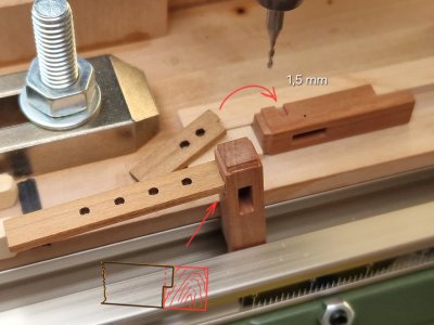
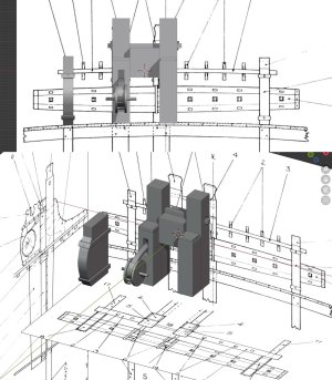
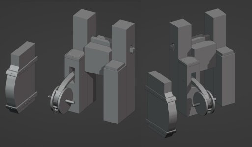
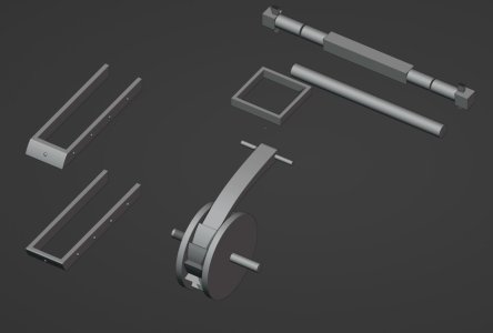
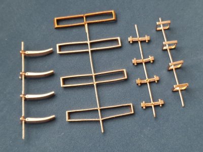
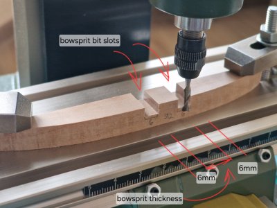
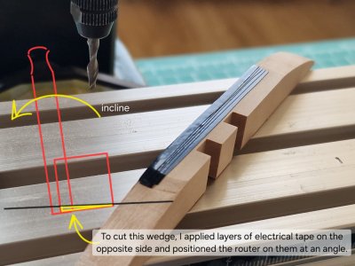
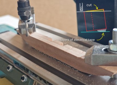
I previously showed how I fabricated some of the wooden parts (the bowsprit bitts). All the metal parts were made using the same method as the others I had shown earlier. The appearance was modeled in 3D software...
View attachment 638446
View attachment 638447
View attachment 638448
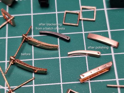
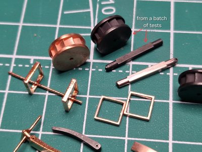
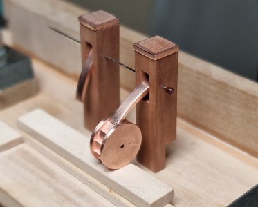
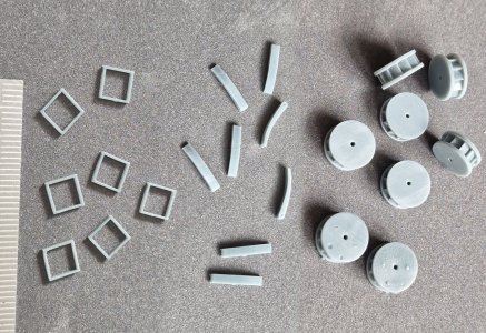
Then, everything was 3D-printed and copper-plated using an electroplating process. After finishing, the parts will be blackened and integrated into the wooden elements.
View attachment 638449
View attachment 638450
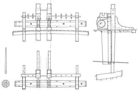
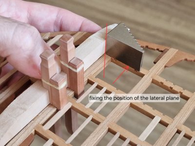
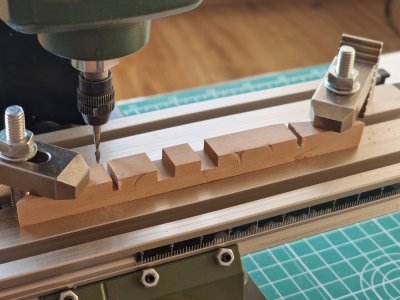
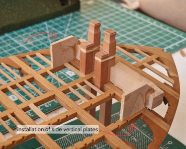
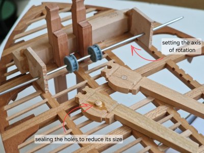
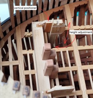
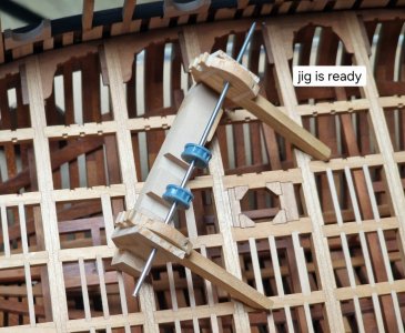
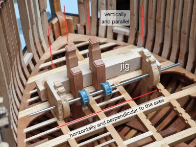
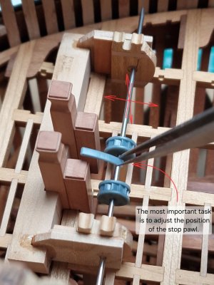
But first, we need to build a jig to accurately transfer all the parameters, positions, and angles of the future components, since we must precisely align the winch, ratchet mechanism, and stanchions with the position of the main bowsprit bitts.
View attachment 638451
View attachment 638452
View attachment 638453
View attachment 638454
View attachment 638455
View attachment 638456
View attachment 638457
View attachment 638458
View attachment 638459
View attachment 638460
View attachment 638461
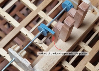
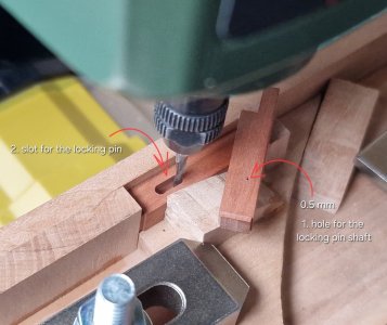
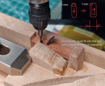
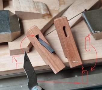
This step took me several days, but without it, it’s impossible to install all the elements accurately and predictably. Each part has its own axis, tilt, and precise distance from other objects. And most importantly, everything must be strictly vertical (relative to the sides), horizontal (relative to the horizon), and set at the correct angles (relative to the keel). Plus, the locking pin has to be exactly in place and align with the right points... in short, it involves endless fitting and checking. But the result will be spot-on.
Sehr clevere Vorgehensweise. Absolut durchdacht und praktisch in der Anwendung. Das Ergebnis spricht für sich. Sehr schön erklärt. Alles nachvollziehbar. Wieder ein weiterer wertvoller Tipp. Unglaubliche Präzision im Detail und in der Vorgehensweise. Ein Modell mit einem erstklassigen „Drehbuch“ .Danke fürs Zeigen.Kapitel 27. An Deck (Teil 5)
Ankerwinde .
1/
View attachment 638445
Ich hatte bereits gezeigt, wie ich einige der Holzteile (die Bugspriet-Klampen) gefertigt habe. Alle Metallteile wurden mit der gleichen Methode wie die anderen, die ich zuvor gezeigt hatte, hergestellt. Das Aussehen wurde in einer 3D-Software modelliert.
View attachment 638446
View attachment 638447
View attachment 638448
Anschließend wurden alle Teile im 3D-Druckverfahren hergestellt und galvanisch verkupfert. Nach der Fertigstellung werden die Teile geschwärzt und in die Holzelemente integriert.
View attachment 638449
View attachment 638450
Zunächst müssen wir jedoch eine Vorrichtung bauen, um alle Parameter, Positionen und Winkel der zukünftigen Komponenten genau zu übertragen, da wir die Winde, den Ratschenmechanismus und die Stützen exakt auf die Position der Hauptbugstpritschen ausrichten müssen.
View attachment 638451
View attachment 638452
View attachment 638453
View attachment 638454
View attachment 638455
View attachment 638456
View attachment 638457
View attachment 638458
View attachment 638459
View attachment 638460
View attachment 638461
Dieser Schritt hat mich mehrere Tage gekostet, aber ohne ihn ist es unmöglich, alle Elemente präzise und vorhersehbar zu montieren. Jedes Teil hat seine eigene Achse, Neigung und seinen exakten Abstand zu anderen Objekten. Und vor allem muss alles absolut vertikal (relativ zu den Seiten), horizontal (relativ zum Horizont) und im richtigen Winkel (relativ zum Kiel) ausgerichtet sein. Außerdem muss der Sicherungsstift exakt sitzen und mit den richtigen Punkten übereinstimmen … Kurz gesagt, es erfordert endloses Anpassen und Überprüfen. Aber das Ergebnis wird perfekt sein.