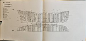
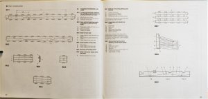
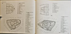
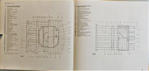
HMS GRANADO - bomb vessel - 1742

Uwek

Administrator
Staff member
Administrator
Forum Moderator
Joined
Dec 25, 2017
Messages
31,162
Points
1,238

Location
Vienna, Austria
Based on the big interest, which was produced by the new model kits devloped by CAF I decided to make a new topic,
showing the basic data and contemporary and new sources existing

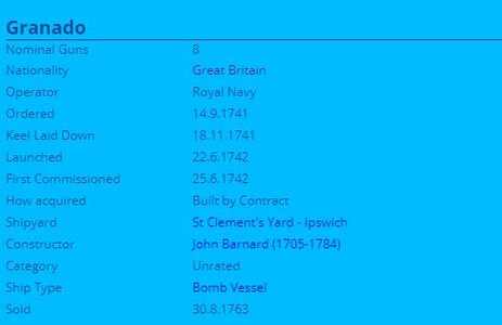
HMS GRANADO (1742)
- bomb vessel -

1.JPG

2.JPG

3.JPG

4.JPG

interesting is maybe also the fact, that the Constructor John Barnard built all together maybe 40 ships, tthe Granado was one of his first ships in the beginning of his career.


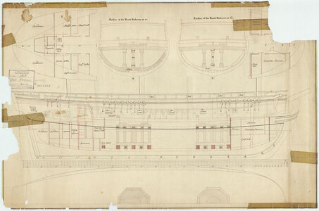
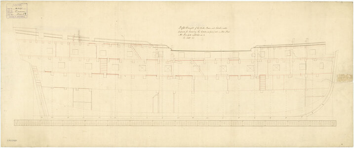
There are several contemporary drawings existing and available at the NMM

j0387.jpg
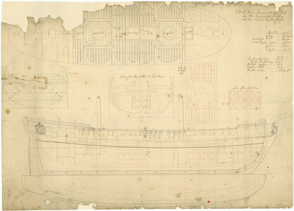
No Scale. A plan showing the body plan with stern board decoration, inboard profile with stern-quarter decoration and figurehead, and a longitudinal half-breadth plan for the 'Granado' (1742). This ship was a bomb vessel.


j7658.jpg
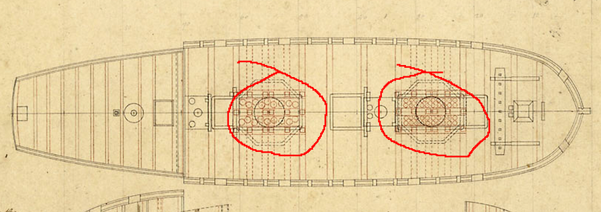
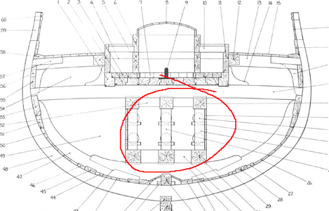
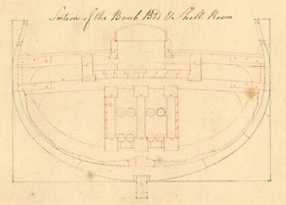
Scale: 1:48. Plan showing the body plan, sheer lines with inboard detail and sketch of figurehead, and basic longitudinal half-breadth for Comet (1742); Terror (1742); Granado (1742); Firedrake (1742); Mortar (1742); Serpent (1742), all 8-gun, 2 mortar, Bomb Vessels. The plan includes the upper deck with platforms and hold superimposed, and a section and plan of the bomb bed and shell room.
Copies were sent in October 1741 to the merchant yards for the above ships.

Unbenannt1.JPG
Here one excerpt showing the cross section
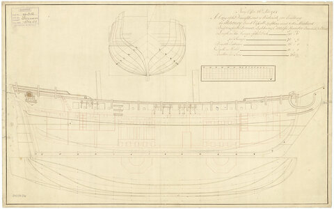


j0390.jpg
Scale: 1:48. A plan showing the body plan, sheer lines with inboard and external detail, and a longitudinal half-breadth with mortar bed details. This plan was used to contstruct such vessels as the 'Alderney' (1734), 'Furnace' (1740), 'Lightning' (1740), 'Carcass' (1740), 'Thunder' (1740), 'Basilisk' (1740), 'Blast' (1740), 'Firedrake' (1742), and all bomb vessels.
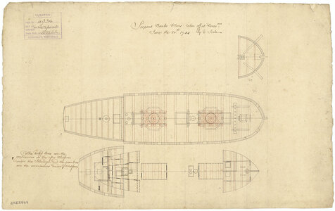


j0339.jpg
Scale: 1:96. A plan showing the forecastle, upper deck, and fore and aft platforms for the 'Serpent' (1742), a bomb vessel, as taken off at Portsmouth Dockyard.


Interesting could be also the drawing of the predecessors Basilisk (1740); Blast (1740) Carcass (1740) Furnace 1740 Lightning 1740 Thunder 1740
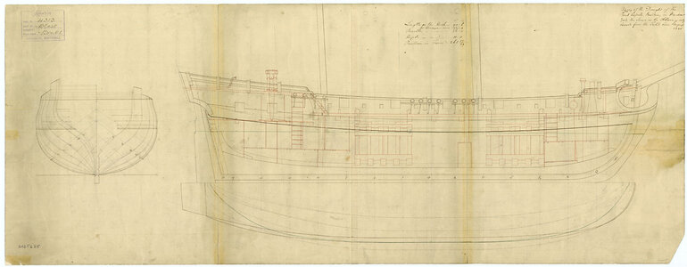
j6764.jpg


especially also the drawings of the HMS Furnace
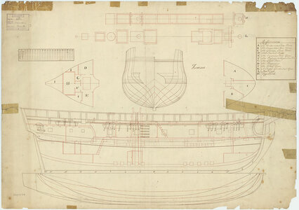
j0515.jpg

j0516.jpg
in Scale: 1:48. Plan showing the body plan, inboard profile, longitudinal half-breadth, upper and lower deck fittings, and fore & aft platforms for Furnace (1740), a Bomb Vessel, as converted for Arctic exploration in 1741. The reverse has 'N. West Passage' in ink.

 
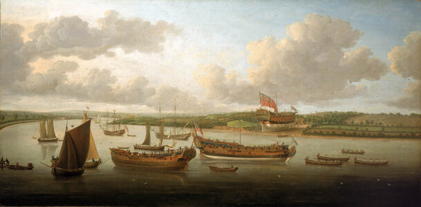
One painting is existing by John Clevely

John_Cleveley_the_Elder_-_Launch_of_a_Fourth-Rate_on_the_River_Orwell.jpg

Launch of a Fourth-Rate on the River Orwell

This is believed to be a picture of the first three naval vessels built by John Barnard the Younger for the Navy Board. It is a composite in both time and subject and is thought to show the 'Hampshire', 50 guns, on the stocks, the 'Biddeford', 20 guns, being towed downstream and, in the left foreground, the 'Grenado', a bomb-vessel. The location is the River Orwell and the artist was positioned in the immediate vicinity of the Frensham Tower several miles downstream of Ipswich, immediately identifiable in the middle distance. The land on which the ship sits ready for launch is John's Ness, where the 'Hampshire' was the only 50-gun ship was built and was launched there in 1741.

The 'Biddeford', a sixth-rate, was built upstream at St Clement's Yard and launched in 1740. She was towed downstream to Harwich to be rigged: no other 20-gun ship was built upstream of John's Ness. This painting shows the boats involved in towing. The 'Grenado' was also built at the St Clement's Yard, the only bomb ketch ever built there, and was launched in 1742. In the picture she is shown without masts but the positioning of her mizzenmast indicates her rig. The bomb ketch was a relatively uncommon vessel with distinctive lines. It is not known why Cleveley selected these three Barnard-built ships launched in different years to appear in the same picture. The work may have been commissioned from him by the Barnard family but no evidence exists to support this.


Two more paintings are existing where the Granado / Grenado is also shown, but unfortunately these paintings are not uploaded until now at the NMM

[Capture of Havana, 1762. Plate 5.] Landing and Marching the Troops along the Shore towards the Fort Cojimar... June 7th 1762. With the Transports anchoring along the Shore, also His Majesty's Ship Dragon and the Bomb Granada attacking the Fort and Batteries

One of the set of 12 published between April 1764 and May 1765 by Lieutenant Philip Orsbridge: see PAH7730. PAH7741-PAH7752 are a complete set.

[Capture of Havana, 1762. Plate 5.] To the Rt Honble George Keppel, Earl of Albemarle &c.&c...Chief of all His Majesty's Land forces at the Attacks and Reduction of the Havannah, This Perspective View of the Landing and Marching the Troops along the shore towards the Fort Cojimar...His Majesty's Ship Dragon and the Granada Bomb, attacking the Fort and Batteries...

One of the set of 12 published bOne of the set of 12 published between April 1764 and May 1765 by Lieutenant Philip Orsbridge: see PAH7730. PAI6303 - PAI6313 are an incomplete set missing plate 3.

 
And we have also several model shown in the collection of the NMM


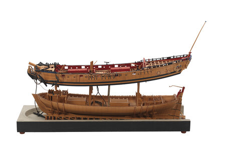
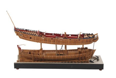
Grenado (1742); Fighting vessel; Bomb vessel

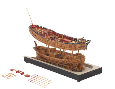
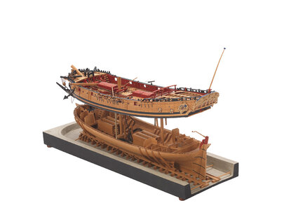
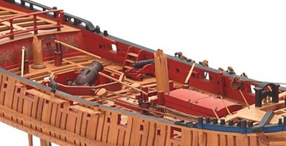
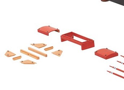
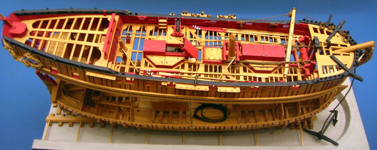
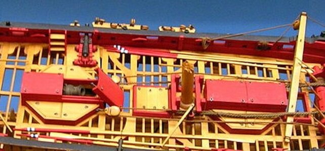
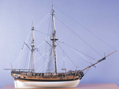
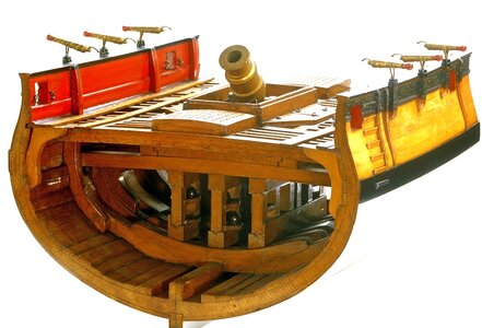
Scale: 1: 48. A full hull and partially planked model of the ‘Grenado’ (1742), a bomb ketch fitted with two 12-inch mortars. The model has been designed to lift apart to reveal the internal construction and layout of an 18th-century bomb vessel. The hull is almost entirely built from boxwood but the mortars have been turned in ebony and painted to represent bronze. It is complete with a wealth of removable parts allowing a visual deconstruction.

The model illustrates how the mortars were operated and where the shells were stowed down below, and it is also has a set of large sweeps or oars as a backup should the wind drop and minor re-positioning be required. Such is the high standard of modelmaking, it was awarded the gold medal in the National Maritime Museum’s First International Ship Model Competition held in Greenwich in 1975.

Vessels of this type were one of many of the ketch-rigged vessels built in the merchant yards. The ketch rig enabled the positioning of two sea mortars amidships and provided a stable platform from which to operate. The ‘bombs’, as they were known, were anchored off shore and employed in bombarding enemy coastal fortifications.

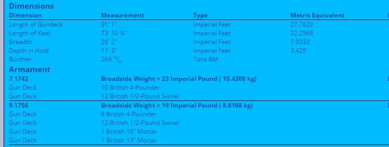
The ‘Grenado’ measured 91 feet along the maindeck by 26 feet in the beam and was 279 tons burden. It had an eventful career and was present at the attack on Martinique in 1759, the capture of Guadeloupe in 1759, the capture of Martinique and the Havana expedition in 1762. It was eventually sold the following year.

ID:SLR0331
Collection:Ship models
Type:Full hull model; Frame model; Plank-on-frame; Separating model
Display location:Not on display
Creator:Lightley, Robert A.
Vessels:Grenado (1742)
Date made:1971-2 (19 January 1971-23 August 1972); 19 January 1971-23 August 1972 1972- 19 January 1971-23 August 1972
Credit:National Maritime Museum, Greenwich, London. Reproduced with kind permission of Robert Lightley
Measurements:Overall: 280 x 690 x 220 mm

l5780_001.jpg

l5780_002.jpg

l5780_003.jpg

l5780_004.jpg

l5780_003a.jpg

l5780_003b.jpg


Granado_bomb_vessel_model1.jpg

Granado_bomb_vessel_modela.jpg


from Jotika:

http://www.jotika-ltd.com/Pages/1024768/Nelson_13.htm

Twelve bomb vessels, including Granado (the sixth), were built at the outbreak of the War of Jenkins's Ear in 1739.

Granado was ordered on September 14th 1741 and the keel was laid on November 18th 1741. Although it is uncertain who designed the Granado, it is commonly attributed to Thomas Slade, the naval Surveyor who oversaw the construction of the ship at Ipswich. Thomas Slade also went on to design famous ships such as H.M.S. Victory.

Granado was unusual in that she was designed to be used as either a sloop or a bomb vessel, being constructed with a conventional square stern.

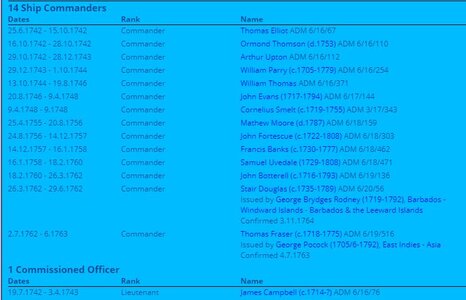
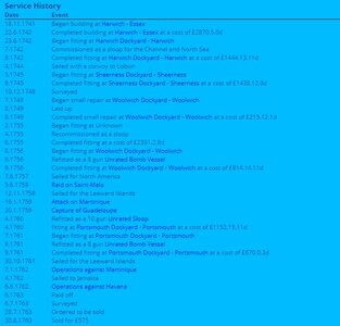
Launched on June 22nd 1742, Granado was taken to Harwich, fitted out and put in commission as a sloop.

An Admiralty Order on July 15th 1745 was issued 'to fit her (Granado) as a bomb' but this order was reversed on July 17th 1745 and Granado remained as a sloop. It was not until 1756 that Granado was fitted for the first time as a bomb vessel from an Admiralty Order on July 26th 1756.

Between the launch of Granado on June 22nd 1742 and her fitting as a bomb vessel July 26th 1756 a number of changes had been made to Granado's configuration as compared to the original Admiralty plans the most noticeable of these are as follows:

1. Two extra 4pdr carriage guns were added (Admiralty order of June 20th 1745) bringing the total 4pdr carriage guns to 10.

2. Two bow chaser gun ports were added allowing accommodation of the extra guns either under the forecastle as bow chasers or at the fifth gunports.

3. The mortars as shown in the Admiralty plans are two 13 inch mortars however when fitted as a bomb vessel this was actually changed to 1 x 13inch and 1 x 10inch mortar. This is confirmed by the provisions list on March 30th 1757 which details 50 large and 50 small shells.

Granado remained as a bomb vessel until the Admiralty Order to fit her as a sloop on March 20th 1760. It was during this period as a bomb vessel that Granado was involved in her most active role.

On January 22nd 1759 Granado and the squadron under command of Commodore John Moore anchored off Basse Terre. The following morning the citadel and batteries of Basse Terre were bombarded. By January 24th troops had occupied the forts of Basse Terre and Fort Royal, the town had been devastated by fire caused by the carcasses discharged from the bomb vessels.

On February 7th, the fleet moved to attack Fort Louis at the entrance to Cul de Sac Bay. The attack began the following day and by February 15 the bombardment ceased with the capture of the Fort.

Granado was again converted to a bomb vessel in August 1761 and she remained as such until she was sold on August 30th 1763 for £575. During this period Granado was involved in the action of capturing Morro Castle and El Morro in the West Indies and the capitulation of Havana on August 13th 1762.


JO9015-Granado-0044--modely-lodi.cz.-.jpg
 
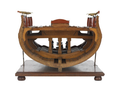
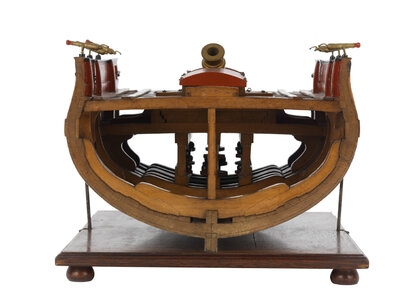
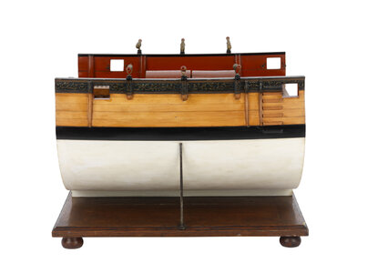
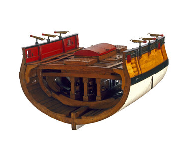
and we know two section models at the NMM


l0277_001.jpg

l0277_002.jpg

l0277_003.jpg

d7812.jpg

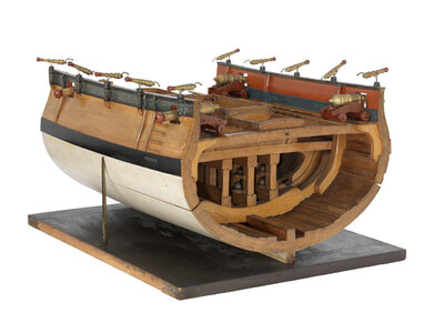
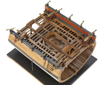
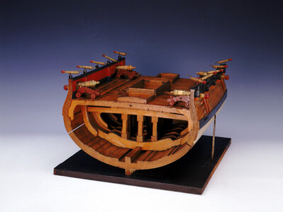
Fighting vessel; Bomb vessel

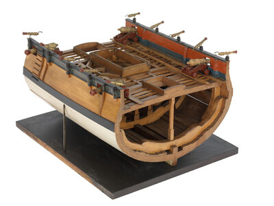
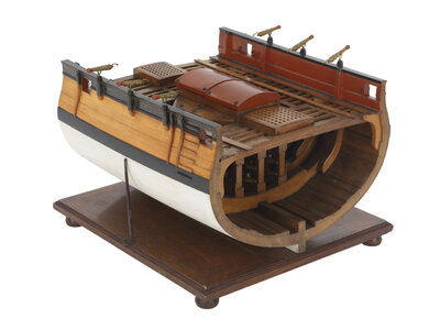
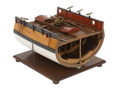
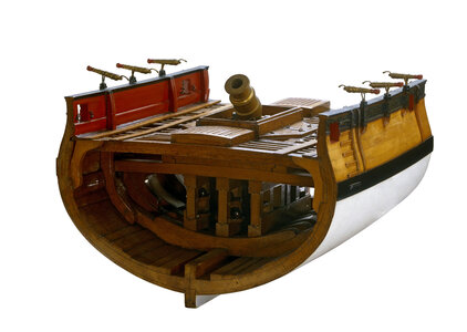
Scale: Unknown. A model of a midship section of a bomb vessel made entirely of wood with metal fittings and painted in realistic colours. The model shows the position of a mortar, bed and platform and the strengthening of the ship's timbers to accommodate it. The hull is carved from solid wood and painted white below the waterline with solid black wales above and stained and varnished wood above the wales. A frieze is painted on the bulwarks featuring acanthus leaf decoration on a blue background. The gunwales are painted black and there are five swivel guns mounted on the port and starboard sides. The deck is shown in frame and features two hatches and four large guns on sea service carriages. All the depicted guns are turned in wood, painted gold with red barrel tips. Directly beneath the mortar position strengthened vertical and horizontal timbers encompass a two-tier shot rack. The model is displayed on a black painted display wooden rectangular baseboard with a pair of stabiliser supports, in an original display case, glazed on all four sides and top.

and the missing dismantled parts of the section model

rs6659.jpg

Warship; Bomb vessel

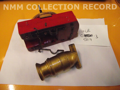
Mortar and bed for the contemporary model of the midship section of a bomb ketch circa 1760. Contained in a bag.

rs6658.jpg
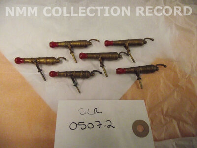
Six guns for the contemporary model of the midship section of a bomb ketch circa 1760. Contained in a bag.

rs6660.jpg
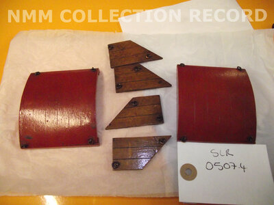
Two hatch covers and four pieces of decking for the contemporary model of the midship section of a bomb ketch circa 1760. Contained in a bag.


another section model
l3126_004.jpg

l3126_003.jpg

l3126_001.jpg

l3126_002.jpg

l3126_005.jpg

f2489_1.jpg

f2489_2 (1).jpg

Scale: 1:24. A contemporary model of the midship section of a bomb ketch circa 1760. The hull is painted white below the waterline and the gunwale above is painted black. The hull above the gunwale has been varnished to resemble planking. Along the strakes three small guns have been mounted on either side of the hull. The framing and knees can be seen as well as deck beams. There are cannon balls in the shot racks beneath the mortar bed. The deck is shown mostly unplanked and in the centre is an octagonal mortar bed with two gratings fore and aft. The mortar covers are open so as to expose the mortar which is shown in an elevated position. The mortar covers, bed and other details have been painted red. The mortar and guns are painted gold. The model is displayed resting on its keel on a baseboard with two stabiliser supports and the baseboard rests on four bun feet. There is a label that reads: "Section of bomb vessel c.1760 showing mortar in position with magazine below". "Folio 1995" and "Folio 1295" are also on label.


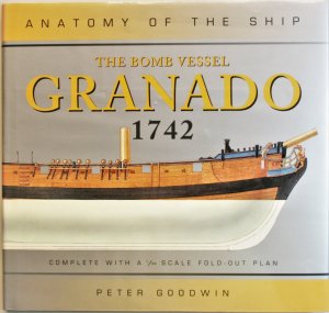
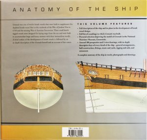
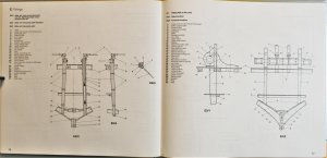
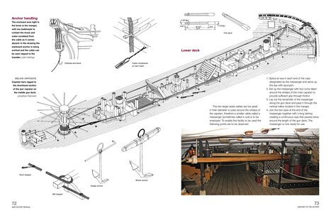
and not to forget the book by Peter Goodwin part of the Anatomy of Ships series


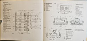
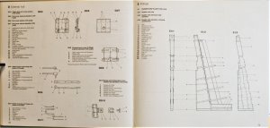
The Bomb Vessel GRANADO (Anatomy of the Ship)
by Peter Goodwin

IMG_41851.jpg IMG_41861.jpg

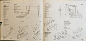
some excerpts ....

IMG_41991.jpg IMG_42001.jpg

IMG_42011.jpg IMG_42021.jpg

IMG_42031.jpg IMG_42041.jpg

IMG_42051.jpg IMG_42061.jpg

you can find the detailed Book Review with Look Inside here:

 
Were any bombs purpose built or were they all/mostly converted?
I guess, I have to check this, that a lot of bomb vessels were purpose built, especially the earlier french one, like the class of the Salamandre with the fixed two mortars firing over the bow.

Bomb vessels were highly specialized and expensive to fit out and maintain, and only marginally suited for their secondary role as cruisers. Because bomb vessels were built with extremely strong hulls to withstand the recoil of the mortars, several were converted in peacetime as ships for exploration of the Arctic and Antarctic regions, where pack ice and icebergs were a constant menace. Most famously, these ships included HMS Erebus and HMS Terror. In this case, the volcanoes – Mount Erebus and Mount Terror on Ross Island in Antarctica – were named after the ships, instead of vice versa.

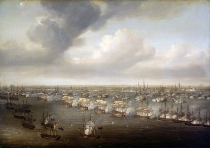
Nicholas_Pocock_-_The_Battle_of_Copenhagen,_2_April_1801.jpg
In this painting of the Battle of Copenhagen (1801) by Nicholas Pocock, Royal Navy bomb vessels in the left foreground fire over the British and Danish lines of battle into Copenhagen in the background


you can search for bomb vessels under "Restrict search to ships defined as"
 
Some more information about the history of the HMS Granado / HMS Grenado 1742 are in the meantime in wikipedia

Especially about her later career as merchantman under the rename Prince Frederick, whaler renamed to Prince Frederick Prudence or only Prudence and finally as a transport until she wrecked

The wrecking occurred on 20 May 1782. Prudence and Union were serving as ordnance store ships when a storm drove them from Calicut roads. They were unable to clear Cotta Point and wrecked on the reefs there.

 
I've ordered my CAF Granado kit, and hope to start construction in about a month. I the meantime, I've purchased Goodwin's AotS Granado book and have been reading and studying it. Doing so has brought to light a number of questions in my mind, mostly to do with in-hull space utilization, which will affect what detail I am able to show there:
  • Where is 1.1km of 105mm diameter anchor cable kept? (That's 120 fathoms x 5 ropes of 13" circumference cable. 2 attached to the anchors, 3 spare.) In addition there's 240 yards of 65mm diameter cable. I see a very small rope storage are 73 on the cross section, but no good way to get anchor ropes to it, so possibly it was for rigging?
  • Where would the mess table(s) and stools be located when used? The galley doesn't seem big enough.
  • Where would the 60 crew sleep? Or even half of them at a time? I realize an accompanying tender would carry additional supplies and crew, but 60 men sailed the ship, apparently for days or longer at a time.
  • Where would the Stream anchor be stored below deck? And could it be maneuvered there with its arm attached, or would it have to be removed?
  • Where would shot for the 4-pound guns (8-12 of them) be stored. I see no provision on-deck or below. Or the 12+ half-pound guns.
  • There is a bread room and galley with firehearth (at opposite ends of the vessel), but I see no food, provisions, water, flour, ale, etc. storage - no kegs or barrels or, really, room for them. Yet she sailed across oceans and was in service for many months. Mention is made the the Boatswain's storeroom was used for some items, and there's supposed to some storage under the deck at the fore, but I can't even find it on the drawings, so it is small. The two "hold" areas are decent size, but it seems like that's where the anchor ropes would have to go.
  • There really seems almost no room for ballast, except possibly below the shell rooms, without impeding the small amount of headroom in other "rooms".
  • While Goodwin shows storage space for 24 of each size bombs, that appears to be storage for once they were loaded with powder, prepared for battle. Provisioning information shows that at docking, 50 of each were placed on-board, and that probably would not used the shell rooms, as they were not loaded. Where were they placed? (BTW, the model portrays the probable arming of the ship with a 13" mortar and 10" howitzer (not a 10" mortar.)
  • Where were the 16 half-barrels of powder placed when provisioning? I wouldn't think they would all be kept in the filling room, but maybe.
It may be said that the Granado was only active during shelling, and needed no long-term provisioning, but it was in Channel service (as a bomb vessel) and other service for around a year at a time. And of course it crossed oceans during its career. Provisioning questions would no doubt still come up when she was converted to a sloop, with the mortar, howitzer and bomb structure removed, as she then had a larger crew of 110. The book mentions that those crew actually firing the bombs were Royal Artillery men, who stayed aboard the bomb tender vessel accompanying the Granado, but I don't know how many men those were, or if they were considered part of the 60 man Granado crew.
 
In addition (looking at the plans and such), I notice that the distance from the deck to the top rail on the forecastle is only about a foot. On the quarterdeck, it's about 2' max, going down to 1-1½'. Not exactly per OSHA standards. Sailors will be working on those decks - how do they not fall off? There's a rail at the end of the quarterdeck about 3' high protecting men from falling to the main deck, and top of wales on main deck are 3.5' or so, but man, that quarterdeck is dangerous. And a single tiller for the rudder? With no apparent means of locking it, for an ocean-going ship in 1742? And no binnacle or other such hardware nearby?
 
Last edited:
During my research, I've found some information concerning the above.
  • Where would shot for the 4-pound guns (8-12 of them) be stored. I see no provision on-deck or below. Or the 12+ half-pound guns
The text of Goodwin's book mention on page 23 in Appeneix1: The Dimension and Scantling List for the Granado 1742:
1712093338454.png
The dimensions to the right above are fee and inch measurements for the items. The mainmast pump well is shown on the drawings, but not the shot locker. How should this size and location be interpreted?
  • Where were the 16 half-barrels of powder placed when provisioning? I wouldn't think they would all be kept in the filling room, but maybe.
In the table "Weight of Stores etc. for the Thunder as Commissioned, 1759" in Goodwin's book it specifies 44 half-barrels of gunpowder. The 16 half-barrels mentioned above are just what was mentioned in a resupply notation.

Turns out the half-barrels are actually quite small, containing only 50 pounds of gunpowder each (100 pounds in full barrels). These gunpowder barrels were much smaller than the casks called "Barrels" for other storage. I've found a size of about 21.6" high by 17.4" diameter at the middle for large, so maybe about 17" x 13" for 50 pounds. I think that even the 44 of half-barrels would fit into the Powder Room (main magazine), so that answers that.

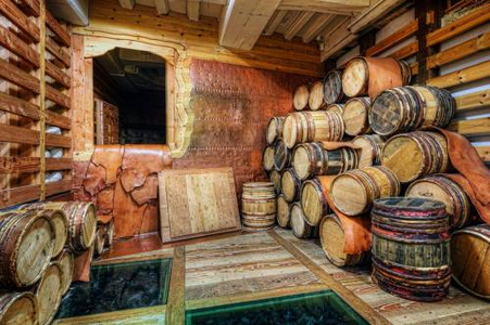
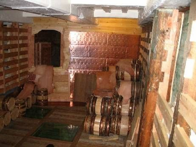
Here's a photos of the HMS Victory's powder room, with (apparently) full and half-barrels of powder:
1712091825306.png
1712095271092.png
I notice these are all ringed with sapling hoops, although recent reading I've done indicates they would normally have been ringed with copper hoops by that time (more probably sapling hoops on the Granado).

One new question:
  • Where were the minimum of 18 oars stored? I think I read on SoS for the Blandford(?) or another bomb vessel they were stored over the rail on brackets? They certainly couldn't be store below.
Any thoughts on these or previous questions?
 
Continuing on with the questions and research I've done.
  • Where would shot for the 4-pound guns (8-12 of them) be stored. I see no provision on-deck or below. Or the 12+ half-pound guns.
First, a clarification (or question). The 4-pound guns are stated by Goodwin as having a bore of 3.7" and a ball diameter of 3.5". However, references I've found, verified by my own calculations, indicate that at 4-pound ball should have a diameter of 3.05". In fact, a 6-pound ball has a diameter of 3.49", close to what Goodwin has said. So, were they really 6-pound guns, or did Goodwin have the diameters wrong?

Further, a half-pound ball would be 1.53" in diameter, which is close to Goodwin's statement of 1.5" bore and 1.25" balls, but not exact.

Regardless, I will assume for the time that the balls are 3.5" and 1.5" in diameter.

As mentioned above, there was supposed to be a shot locker in the vicinity for the mainmast pump well. Let's see what size would be required:

The Thunder provisioning indicates there was 6,006 pounds of standard and grape shot for the 4-pound and half-pound guns. Given that HMS ships usually included "X" shots for each gun, and that there are 8 4-pound and 12 half-pound guns, each "X" shot would be 8 x 4 + 12 x 0.5 = 38 pounds (32 pounds of 8-lb and 6 pounds of half-pound), or about 84% for the 4-pounders. So of the 6,006 pounds of shot, about 5,045 would be 4-pound (3.5" diameter) and 961 pounds would be half-pound (1.5" diameter). That's about 1,261 3.5" balls and 1,922 half pound balls.

Using very loose random packing rules that gives:
(4/3*pi*(3.5/2)^3)*1261/0.56/1728 = 29.25 cubic feet of shot locker volume for 3.5" balls and​
(4/3*pi*(1.5/2)^3)*1922/0.56/1728 = 3.51 cubic feet of shot locker volume for 1.5" balls. About 33 cubic feet total. For example a 2' x 2' x 8' area.​
Sounds reasonable, but where was it located?

Also, that seems like a LOT of ammo: Jean Boudriot in The Seventy-Four Gun Ship states the standard was 60 rounds per gun, whereas the above is well over double that. Methinks there might not be as much shot as indicated.

Just for the heck of it, I'll calculate how many pounds of gunpowder it would take to fire all those weapons:
For the 4 pounders: 1261*1.75 = 2,207 pounds of gunpowder​
For the half-pounders: 1922*3/16 = 360 pounds of gunpowder​
That's 2,567 pounds total to fire every 4# and 0.5# projectile on board. Only 2,200 Pounds of gunpowder was loaded, per the Thunder list, so all could not be fired. Or another way to look at it would be: not that much shot was required. If the British standard of 60 rounds per gun was used instead of the above quantities, a total of less than 1,000 pounds of powder would be used.
  • While Goodwin shows storage space for 24 of each size bombs, that appears to be storage for once they were loaded with powder, prepared for battle. Provisioning information shows that at docking, 50 of each were placed on-board, and that probably would not used the shell rooms, as they were not loaded. Where were they placed? (BTW, the model portrays the probable arming of the ship with a 13" mortar and 10" howitzer (not a 10" mortar.)
I still don't know where the extra 26 of each shell were located. Since the shells were empty of powder, they could be thrown into the Mortar Shell area, perhaps? (OK, thrown is a misnomer - they weighed 197 pounds each empty.) I notice that on the HMS Victory, about 1/3 its iron shot was stored below the coal hole, so perhaps some of this could be used as ballast?

Also calculating gunpowder usage here, for 50 bombs of each size:
For the 13" bombs: about 13.5 pounds of powder was used for each propellant charge and 10.25 pounds for the explosive. Likewise, for the 10" bombs, 6.25 pounds of powder was used for propellant and 4 5/16 pounds for explosive. So powder usage would then be:
For the 13" bombs: 50*(13.5+10.25) = 1,187 pounds​
For the 10" bombs: 50*(6.25+4.3125) + 528 pounds​
A total of 1,715 pounds of gunpowder to fire all 100 bomb projectiles onboard, with 2,200 pounds of gunpowder total available. Sounds reasonable to me.

Lacking enough powder to fire the 4-pound and half-pound guns to their maximum is probably not a problem. If the Granado were bombarding a city, the 4# and .5# guns would have no use. And if they had to protect themselves from other ships, they'd still be able to fire almost all their shot. Just not both.
 
In looking more closely at the contemporary drawings Uwe posted above, I see very different bomb room arrangements:
1712114763876.png
This seems to indicate 18 bombs per level for the 13" and 40(!) bombs per level for the 10", making 36 and 80 total for two levels!
(Image enhanced for clarity)
1712114808762.png
This arrangement appears to show 24 shells for each level, although I'm not certain what size shells those are.

I just now noticed that the above diagram is from the Serpent rather than the Granado, but other drawings above show still other possible shell arrangements, none of the looking much like Goodwin's.

Those are very different than what Goodwin shows:
1712114983651.png
1712114999309.png
The CAF model appears to agree with Goodwin, although is that correct?
  • I also notice that nowhere is a messenger cable mentioned for the anchor cable. Goodwin just says "The [anchor] cable passed in through a hawse hole at the bow of the ship and then passed to the windlass, around which it was turned; it was then carried aft to the main hatchway, where it descended into the cable tier." The kit appears to include the messenger cable as do the photos above of the wonderfully done split hull model.
 
sheel storage:
Not only Goodwin and CAF made the arrangement of the bomb storage in direction fore and aft between the pillars, also this arrangement is shown in the contemporary section models
f2489_2 (1).jpg

and in my opinion it is the only way, which I can see and imagine in the moment

when we take a look at the drawing

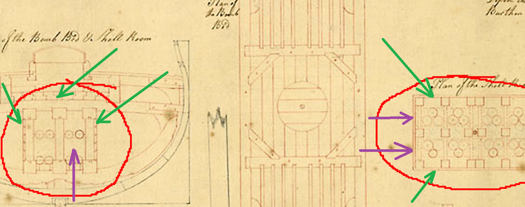
1712114808762.png

The only access would be from the front endings (purple arrows)
from the sides there would be no access because of the wooden walls and also from the top no access because of the massive wooden floor base of the mortars (green arrows) If the shells would be arranged like this the seamen have to climb over the shells
-> therefore I have my doubts that this drawing is correct
 
A very important information which has an influence on several checks

1) When a bomb vessel like the Granado was on service, or better in action participating in a bombardment or raid -> these mortar ships were permanently supplied by special supply ships, often sloops, which supplied shells and powder, but also all other necessary things like water, food etc.
Such bombardements were often over weeks and even months
these ships are called "store ships" at threedecks
as an example here the HMS Crown, which was a 5th rate 44 gunner and converted into a 24gun storeship - here you can see the adjusted openings for the storage access
crown.jpg

2) the normal armament on bomb vessels was only for self protection, for example boat attacks, but a Granado was not intent to use the guns in a normal action. bomb vessels were escorted and protected during bombardements or sailing to a raid by other vessels like frigates (5th and 6th rates)
 
I also notice that nowhere is a messenger cable mentioned for the anchor cable. Goodwin just says "The [anchor] cable passed in through a hawse hole at the bow of the ship and then passed to the windlass, around which it was turned; it was then carried aft to the main hatchway, where it descended into the cable tier." The kit appears to include the messenger cable as do the photos above of the wonderfully done split hull model.

I do not think, that the Granado had a messenger cable, because such a messenger you need only when they used a capstan for lifting the anchor. Here the messenger cable was arround the capstan


918xfJIVWcL.jpg

around the windlass the "real" anchor cable was layed - so no messenger necessary
 
sheel storage:
Not only Goodwin and CAF made the arrangement of the bomb storage in direction fore and aft between the pillars, also this arrangement is shown in the contemporary section models
View attachment 439501

and in my opinion it is the only way, which I can see and imagine in the moment

when we take a look at the drawing

View attachment 439502

The only access would be from the front endings (purple arrows)
from the sides there would be no access because of the wooden walls and also from the top no access because of the massive wooden floor base of the mortars (green arrows) If the shells would be arranged like this the seamen have to climb over the shells
-> therefore I have my doubts that this drawing is correct
Thanks for all your responses. I really appreciate them.

That is probably true. However, no matter the bomb storage pattern, the shells at the end are reachable. And removing them gives access to the ones behind. Of course, the opposite when initially storing: Move the first inward all the way, then store others in front of that.

Two points, however, make this dense of storage less practical: The shelves that store the shells would still be in the way of getting further in. And stored like shown to the right above would appear to make them touch one another, and iron shells, loaded with explosives, rattling against each other could be called BAD®!
 
Back
Top