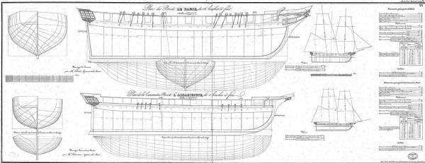
HMS Guadeloupe (ex french Le Nisus), Brick de 24 by Jack.Aubrey - 1:48 scale

Tuesday, September 23th, 2014

Another small step forward: I've added new lateral reinforcements close to the toptimbers and the deck.

This is probably not strictly necessary to guarantee the hull being crushproof but you must know that I'm obsessed to build strong models. So, this afternoon, I amused myself to reinforce again . .

01 Brick%20de%2024%20Plans/P1090992_zps03457775.jpg
y4mxe2LjDvUE9vRL83qz2kmi0J-f1uYTJf5mFWqq


02 Brick%20de%2024%20Plans/P1090994_zps484f9230.jpg
y4mCHcJJ3PqVZo1N9vGorf-msrBHriAFc1ghL0SO


03 Brick%20de%2024%20Plans/P1090989_zpsb02ec9fe.jpg
y4moW7V8Q-JOl436HCN1DFCFx9YZ9T3kyQpbcC3D


04 Brick%20de%2024%20Plans/P1090991_zpsedf348aa.jpg
y4mSYR_WWqPV9ycbEnam9nQ5kdzrclX8A-q6qnIC


05 Brick%20de%2024%20Plans/P1090993_zps7956957e.jpg
y4mfti2UgD3rkiDC7xcVXKv5cuas1P5HYMdGe-0Q
 
Wednesday, September 24th, 2014 - Some Pictures of "Le Cyclope"

In the absence of new material from my model to show, I start to post some messages in which you can understand what kind of sailing ship I'm building and its appearance once finished.
I'm starting with some pictures of a model of an unknown author, although I think should be B. Frolich, of one of the 22 bricks de 24 designed by Pestel.
It is "Le Cyclope".
Le Cyclope was set up in 1804 and launched in 1810 in Genoa. Armed with sixteen 6pdrs guns she was transferred to Italy in June 1810.
Good vision, Jack.Aubrey.

01 Le%20Cyclope/dsc_0336_zps99d9a8ea.jpg
y4mlqpL9la2JLx1jSRzC1a9IX7HbES_qq9yYoPuK


02 Le%20Cyclope/dsc_0338_zpsd16f2304.jpg
y4marJA3psoRv6E5OOTxKBWvyTYUfrYnyzjpwzxQ


03 Le%20Cyclope/dsc_0339_zps3651ac8f.jpg
y4mmO2PIUx7tlHrLYxC2dmCF-4vUhHMeNfzli2P_


04 Le%20Cyclope/dsc_0340_zps2e72d043.jpg
y4mlZ3VCdg4n2ZNBcQGchhWTbzArYMaHfmCsUy3h


05 Le%20Cyclope/dsc_0344_zps699eb6e5.jpg
y4m-DmTjK3seWlWPsyP3CsWbd1k7PXgBnMWFvjcC

To be continued . .
 
Le Cyclope . . Continuation

Here follow five additional images of the brick Le Cyclope.

06 Le%20Cyclope/dsc_0392_zps0bc504a8.jpg
y4mFLHtu1bGWgqva6NRY3JIjEv2ZPen84CmbYcV1


07 Le%20Cyclope/dsc_0361_zps23f1d9fc.jpg
y4mYrL6FY22uQjpD3p_-xzjcqUslpQS28NfE2gEe


08 Le%20Cyclope/dsc_0352_zps1f439ef9.jpg
y4mFY67mNRsRgMP80qYQHJD9_2ePdJ7rR_NPsz0T


09 Le%20Cyclope/dsc_0350_zpsf62d22cc.jpg
y4mPQ_0XHI_usOZht_q-RTT2cl8UJUclMZWMIwLv


10 Le%20Cyclope/dsc_0346_zpsb159620d.jpg
y4mbrclCVPDs9qJsmhvZVYJJVMKKWyEyYTm7PgFR


That's all for "Le Cyclope". I apologize for the dust . .
Regards, Jack.Aubrey
 
Wednesday, September 24th, 2014

I've completed the installation of the lateral reinforcements at the poop as shown in the following picture . .

01 Brick%20by%20JackAubrey/ca8e53ef-cec4-4139-8c3d-ec00064093fe_zps6a2e4853.jpg
y4mdXkET60Pw6X3qPwV5dRLAyWsmfUYUJc_6OwYU


. . and the same was also made at prow. Now all the bulkheads are connected together through these reinforcements and the result is very rigid and strong. This also gives an idea of the sheer of the deck.

02 Brick%20by%20JackAubrey/24aa2826-0150-4342-a0eb-d35d1b59b315_zpscde3a7e9.jpg
y4mM1Kc6v4kq9CSSQAG4Zp-wQJgG2f79vAe-8cPN


Then I worked around the prow, adding the toptimbers to the stem in order to obtain a supporting structure for the planks there.
I've also reinforced the two toptimbers of the first bulkhead by adding a small piece of plywood to enlarge the existing ones. This detail will help when I'll have to bevel this bulkhead.

I would like to explain that all the toptimbers will be removed when the planking will be in place . . but this is a matter that I will discuss better in the future, probably now is too early . .

03 Brick%20by%20JackAubrey/0afe5d3a-551b-45c8-9277-6920ab4e91de_zpsa43ac47c.jpg
y4mWRWFbJW0MzvlZMYVj6KWHXNUOTaT_hP8rl7cb


A detail of the toptimbers at the stem . .

04 Brick%20by%20JackAubrey/P1090999_zps868aba59.jpg
y4mQY2vibEgeOTHEUKqk7T0rQN6U11MLT3cFwWk0


In the next message I'll show some overall views, regards, Jack.
 
As promised, some overall views of the hull . .

01 Brick%20by%20JackAubrey/P1090995_zpsdf171607.jpg
y4mavsJpOsSDxz7TN1eiVHS8ZckMAvcaBx2XrB5W


02 Brick%20by%20JackAubrey/P1090996_zpse1dd41aa.jpg
y4mJQYJhZbYryqtBqlQb2WTzfqL3Xa0HHpkB__4U


03 Brick%20by%20JackAubrey/P1100002_zpsc51d362f.jpg
y4mq_xPOVI95i5-AAOSCffa8Wa9MyM4TosiLeV0B


And last but not least the prow completed with the filler blocks, although not yet sanded.
Next step i'll attack the poop. Hoping in a good result.

Greetings, Jack.

Brick%20by%20JackAubrey/CAM00340_zps1b9ae24d.jpg
y4mZQA7_u5ZYXDr9I9iWo_ydnP0EKY-7_D1E0Hj-
 
I continue with a series of images of another "brick of 24", belonging to the same class of Le Cyclope.

This model depicts "Le Cygne"
, the model described in the monograph from ANCRE. Even here I do not know who the model maker is but surely he well knows what to do and how . . and it pays more care in removing dust from the model before taking photos of it.

Unlike Le Cyclope, Le Cygne mounted 24pdrs carronades and only two 6pdrs guns at bow. Here are three major differences:
- The figurehead
- The poop lateral "bottles" and the kind of decorations
- The gunports size
, that are much larger on Le Cygne than the same of Le Cyclope; I believe that this difference is due to the presence of carronades instead of the guns, to provide a greater visual shooting to carronades.

Here below five images of Le Cygne. . to be continued. .

A cordial greeting, Jack.Aubrey

01 Le%20Cygne/dsc_0600_zps7c6c0c60.jpg
y4mz1hRiA45jCVBVeuEswvrJFFv1jAE7d1P1JaFn


02 Le%20Cygne/dsc_0601_zps33d3b303.jpg
y4mC_jyhPQU9r3172xycYJY47bhhYIw4Y_V3bPCi


03 Le%20Cygne/dsc_0603_zps00d08111.jpg
y4mmyzypXn6V3mO2zx4t-fbjJsojpVgHuoaHA-SO


04 Le%20Cygne/dsc_0607_zps5bfa66b6.jpg
y4mWkp55YW_edVZ0Y4MCvYrBMKC4Egdo5sQh2MBL


05 Le%20Cygne/dsc_0609_zps558b5763.jpg
y4ma3u247tnrHiPyd8dwsngiQvdq5MnpmhXXN6qD
 
Le Cygne . . Continuation

Here below five other images of the brig "le Cygne".

01 Le%20Cygne/dsc_0611_zpsbbb8f515.jpg
y4mA9m63lsFs30n1o36jupsqXToX2bfuGDr_3EhU


02 Le%20Cygne/dsc_0614_zps85484955.jpg
y4mogAc5pyxfuJ1abdJjttDYq4H5mhCRbUQZGnmC


03 Le%20Cygne/dsc_0615_zpsadfe6f10.jpg
y4muawpUE4P1uyM0z8FWSmyqnYN89-EWROtPR_-8


04 Le%20Cygne/dsc_0617_zps2c8301cd.jpg
y4moDPdFspuLaH4JX9oxgWXb5gsNSdH4itIb-PS0


05 Le%20Cygne/dsc_0619_zps421f9278.jpg
y4mYXynHaoXIfFSp6aerA-Z_wKyxkH6xRLGjqmek


That's all regarding this ship/model. Regards, Jack.Aubrey.
 
Monday, September 29th, 2014

As I wrote some time ago, at the beginning of this discussion, the model that I am building belongs to a class of brick which has 20, ships designed by Pestel, or 22, if we count the two variants built without changes by Sanè when Pestel fell into disgrace with the major staff of the French Navy.

As I got to write many of these brick were captured by the British and subsequently used into war actions against the French themselves. I have also indicated my intention to build the model of one of the sailing ships belonging to this category and I've identified among these ships nine vessels that, for their acts of war, interested me in a particular way.

Finally, I also wrote that I had not chosen the name of my model, a name that should fall among the nine selected, explaining that I would have to perform more researchs to identify how the figurehead and stern decorations of these models were in the reality.

. . this research (carried out exclusively via the internet) till now did not yet provide results to be able to determine for example, as the figurehead of some of the nine sailing ships concerned was and I'm not confident in succeeding in the future.

What I was able to establish, by visiting the Maritime Museum in London, was the fact that many of their models have been completed WITHOUT the FIGUREHEAD.

Deepening the topic I noticed that in this case the model does not represent a specific sailing ship, in these images we are speaking about frigates, but represents an hypothetical sailing ship belonging to a particular ship class. In this case, as shown by the images here below, taken from the NMM site, different solutions have been adopted for the figurehead:

1) a flourish dummy
2) a block of wood just sketched
3) a vacancy in place of the figurehead

The three solutions are visible in the screenshots below.

Should a similar solution be eligible for my model in order to have total freedom of choice for the name to be assigned to?

Heavy matter, need more thought to decide . .

01 Brick%20de%2024%20Plans/large_zps88b3f2a2.jpg
y4mfEAghk0WuWVz1WO9CQSDGNYAJHU1zoknvDy4H


02 Brick%20de%2024%20Plans/large_zps001cab09.jpg
y4mRTdP0VU9Hpt4pwp8Zg2UMI6xPvsKEOZKIo8rZ


03 Brick%20de%2024%20Plans/large_zps0b606ee1.jpg
y4mKYCkSeH851Ng9JD37ND_6tNBVbgR9zqDrD5VF


04 Brick%20de%2024%20Plans/large_zpsdc4d6b3b.jpg
y4mlvhKThTnWKJ6C7nlITYhnqzxIJEC-ZqejSuig


05 Brick%20de%2024%20Plans/large1_zps6fa11a99.jpg
y4m2wzssHT3Lf5rRIRQHFaRLfhK41aVb7JXmo-aY
 
I had the possibility to identify exactly the authors of the two models I presented in this topic.
The Authors (with the A in capital letters) are:
for Le Cyclope, Bernard Frölich
for Le Cygne, Jean-Claude Buchaillard

I'm seriously considering a fourth alternative for the figurehead, I'll explain better.


I wrote that it's my intention to build a brick captured by the RN and I have selected 9 potential candidate. The nine brick to which I refer are those listed below. I tried their translation into Italian and I got interesting references. The original French name represents, if I understand correctly, birds and in some cases mythological characters.

Curieux >>> Curious (??)
Phaeton >>> Phaeton (mythological) but also a bird
Voltigeur >>> Acrobat
Griffon >>> Griffin
Basque >>> Basque (??)
Lutin >>> Sprite, elf, goblin
Nisus >>> Nisus character of the Aeneid or Sparrowhawk (Accipiter Nisus), bird of prey
Milan >>> a bird of prey of various species (see Wikipedia)
Colibrì >>> Hummingbird

It's likely or plausible that the "bird" ships had a kind of figurehead like Le Cygne, which represented the bird its name implies, while for others it would be even easier for Phaethon (mith), Nisus (Aeneid) and a little less for Curious, Acrobat and Elf . For Basque just would not idea.

In the ANCRE monograph it seems that this logic may be applied.

According to the previous list good candidate names may be: Griffon, Nisus, Milan, Colibrì, Phaeton (bird) and probably also Lutin. Internet provides lot of images usable for these names.

Here some examples . .


Nisus post-1168-0-75114900-1412197948_thumb.jpg


Colibrì post-1168-0-93022100-1412197949.jpg


Phaeton post-1168-0-73628600-1412197951.jpg


Griffon post-1168-0-00286200-1412197965_thumb.jpg


Milan post-1168-0-42116000-1412197966.jpg
 
Friday, October 3, 2014 - Structure of the stern

I put aside for the moment the figurehead "dilemma", although the topic remains open, to move on.


It's been several days since I posted new pictures of the state of the shipyard and what I am about to show may appear a very small thing for those who have not experienced the problems I lived.
In fact I could not spend the time on the model as I wanted because some commitments did not allow me, but apart from this detail, in fact, after a first attempt that did not achieved the results I expected, I had to disassemble what was wrongly done and start over with some variations. The explanation is all here.

In the first picture you can see the exterior of the stern, which is slightly curved and "square" shaped, shape that is to be considered temporary. In fact, the next step will be to cut out the contours to the shape of the plans. At the time the sizes are quite generous. But from the outside, you don't understand how this structure is built . .

01 Brick%20by%20JackAubrey/P1100034_zps83e0931a.jpg
y4mrfEjTPQ9BxTIUPLoiwAuBQwINaxffBJMyMhHB


Instead, the view from inside should serve to show how everything is set up.
In fact we can identify three elements that compose it and which, together, provide the thickness and adequate strength until the planks will not be applied:

- Four shaped supports which are fixed to the last bulkhead and provide the base for the other two elements. They are made with special plywood because I felt very sturdy and therefore unsuitable to use the classic poplar plywood. However, it is the same material used for the keel.
- The outer part consisting of two shaped plywood pieces of 1,5mm. applied externally to the previous element. The top one is simply rectangular, the lower one has a shape that I had to get empirically by testing first with cardboards until I identified the right one and then copy it on to the plywood.
- Once the second element was fixed the next day I proceeded to stiffen the inside using lime 8x2mm strip glued properly. Note the need to cut with a given angle the side that met the internal angle and the bulkhead. To do this was very useful the power sander that I bought from Proxxon time ago.

Now that everything is perfectly dry it looks like a very strong structure able to deal with the stress of the next processing.

02 Brick%20by%20JackAubrey/P1100033_zps8b1cb266.jpg
y4muywluYtPczTHOJmT_9yJvPsajmUsAV4h_6JZo


Finally, an overview of the whole skeleton of the hull.

03 Brick%20by%20JackAubrey/P1100032_zps1be31e11.jpg
y4m2ch3vXeVHZQ1T8F-w97U4125eBZ5oG5sAmgsS


To be continued . . Regards, Jack.
 
Monday, October 13th, 2014

Today I overcame my reluctance to make dust and in the afternoon I set a good pace to shape the bow and adequately prepare the bulkheads with the "famous" bevel angle.

Below you can see the bow area, where there was to sand more with power and manual tools than in other areas of the hull:

01 Brick%20by%20JackAubrey/CAM00347_zpsf4527c5b.jpg
y4mM4zrlsw6umLUgFWtmUaDhV-C_NGQjiXJ-D4vm


But even in the stern there was enough work to do, in particular for shaping appropriately the transom in order to make possible to glue the last piece of the planking. Here a view of the internal side:

02 Brick%20by%20JackAubrey/CAM00348_zpsd8c6be91.jpg
y4mJoWstAwByaYBPiLbRoTcwjZh1AOp84TBV9NNN


While here below I propose a view of the transom from the outside. As you can see the stern looks more like a stern than before I worked on it. In due time, I will also shape the top side, the horizontal one, of the same.

03 Brick%20by%20JackAubrey/CAM00349_zpsccdb1613.jpg
y4mH43TXmGOQY5rn13P7o96wMxriArJODg71hIi0


However also the entire hull, limited for now only to the part above the waterline, has been sanded properly. In fact, the next step will be the installation of the planking at the top of the hull, in particular on the external and internal sides above the main deck. The lower hull will be planked in a second time, when the top is complete and will be possible to capsize the hull without risks:

04 Brick%20by%20JackAubrey/CAM00351_zps0760046a.jpg
y4m1S8foKNJFp1TnB_fXcuJohriPedYE54lKd_Nf


To do this work, today I used a new entry: the belt sander BS/E (or BSL 220/E) from Proxxon. A couple of tests on pieces of wood to waste just to make some experience with the tool and then I started . . it works pretty well although quite noisy and tending to heat up quite a bit after you use it for some time.

Brick%20de%2024%20Plans/BSL220E_zps8f1f50f3.jpg
y4mICNJhWk1BNStnYqd9Go9fO9WnrJNYIPD4m15C


Kind regards, Jack.Aubrey.
 
Wednesday, October 15th, 2014

Today I started to apply the first planks. .


These are strips of lime wood, very beautiful, size 6 x 2 mm, purchased at a model hobby shop in Milan hinterland.
The first strip, in the photos the lower one, is in one piece and has been installed according to the line references of the deck, references which were previously marked on the bulkheads with a small incision on the outside and passed through with a pencil. With this one piece plank I secured a very accurate alignment and natural sheer.
Then I started to apply shorter planks concentrated in the area from amidships to the stern to rise, in order to properly cover the deck walls.
Next activity to reach the same situation from amidships to the bow. I hope tomorrow. . friendliness, Jack.Aubrey

01 Brick%20by%20JackAubrey/CAM00352_zps7734b1f0.jpg
y4mIdoijC9nDQEpVfpvVakW63kKkCPWgRKqQkDje


02 Brick%20by%20JackAubrey/CAM00353_zpsa31b4e8c.jpg
y4m_ryDR58VJ2d9NbBTERfW3SIDxeHXdHBTXG35W


03 Brick%20by%20JackAubrey/CAM00354_zps5195574f.jpg
y4mmn__CB2mvgW0MzRhe5VeVI3VQjivlM64Y9sA1
 
Saturday, October 18th, 2014

In these days since my previous post, where I showed the state of my model, I finished to install the upper planks in the bow area. Here, with respect to the stern, there was an additional difficulty due to the need to properly fold the strips.
My method, now standard for me and described in another topic in this forum, uses a metal can, fixed on a stable base, with a small candle inside that warms the upper surface of the can. I place the wood strip, previously put to soak in water for some time, and I model it to the desired shape. For me now it's child's play and the curves come very natural.

As always, I emphasize the fact that the strips (6 x 2 mm), in addition to being glued to the bulkheads, are also glued together so that they constitute a very solid and robust surface. As always I uses vinyl glue and, where necessary, clamps to hold or brass nails (not completely hammered, so that I can easily remove them when the glue is dry).

At this point, the external bulwarks size is pretty much over, missing only a final "on top" strip of 4 x 2 mm which I will apply later.

Finally today I focused my work on the bulwarks from the inside. In the following photos you can look at the work done inside, where I fixed generic pieces of strips vertically. The thickness of these strips is 2 mm.
The combination of the horizontal outer planking and the vertical internal planking has now a depth of 4 mm and the whole has a extraordinary rigidity and robustness.

But let the pictures speak for me . .

Three-quarters of the bow on the right side . .

01 Brick%20by%20JackAubrey/P1100041_zpsbe8f420f.jpg
y4mCoj_PaCW_ViLkn3bos7hzU5VYjbcB6nPsZNHp


Again three-quarters of the bow of the left side . .

02 Brick%20by%20JackAubrey/P1100043_zps074deab0.jpg
y4mgnuMR2ZC_AQe76esGxPsOrYzk3duT97_SojLn


Other views from different viewpoints . .

03 Brick%20by%20JackAubrey/P1100036_zpse95a5ac2.jpg
y4msc6jbUdoAmwPIR7Sf9Ic2pplWh-biFku5ZVNy


04 Brick%20by%20JackAubrey/P1100042_zps0722b0a6.jpg
y4mHCryuq38d8elo3sC9vruxSstRglCxMiSmbEhn


05 Brick%20by%20JackAubrey/P1100040_zps857068ca.jpg
y4mtl4jy9ap5A1S7QqY1fsrBjgFpCV2fbeTioLKO


In the next messages I will deepen the internal construction of the bulwarks to show where I'm going. .

Friendliness. . Jack.Aubrey.
 
As promised I try to explain more in detail the process of building the bulwarks.

Before continuing with the application of the planking downwards, I decided to finish all the area that now is already planked. This part of the hull, being a brick a single decked ship, is the area where the gun-ports will be opened, and inside, the deck will contain all the superstructures of the model.
The thickness of the bulwarks, according to ANCRE plans, is reported to be 6.5-7 mm, and then I found myself faced with two possible assembling solutions.
Given that a second planking is planned, made with veneer of a wood not yet decided, with thickness of 0.5mm I proceed to describe the two options:

1) sand and level the available toptimbers, already part of the bulkheads, to a thickness let's say of 3 mm, and then apply the internal planking based on strips of 1.5 mm thick; the result will be 2 (external planking) + 3 (toptimbers) + 1.5 (internal planking) + 0.5 (second planking of veneer), with a total thickness of 7 mm. During the opening of the gun-ports I should expect that there will be a vacuum inside, to hide properly;

or

2) a: fill with strips with thickness of 2 mm the internal spaces between the toptimbers; these strips, to strengthen the structure, should be placed vertically; b: then repeat with other strips of the same thickness but placed in a horizontal manner; in this way we have reached a total thickness of 6 mm of a virtually all solid wood, a real "sandwich"; c: at this point level the toptimbers properly and d: by applying the veneer (second planking), both externally and internally, reach the desired thickness of 7 mm. The opening of the gun-ports will always find solid wood.

Personally, I chose the second solution for two reasons:

1) even if it may appear more complex it is much easier to achieve in practice, you just need a bit of patience due to the fact you are managing many small pieces of wood;
2) the structure thus obtained is extremely sturdy, virtually indestructible . . and for a fanatic like me this robustness is crucial.

And the images that follow, which have more details of those I proposed yesterday, show what I'm doing.
The first two figures show the first inner layer of strips placed vertically, fore and aft. The wood used was got from my stock of strips and I think they are larch, wood good and hard enough but that is not usable for finishing because the grain is too exaggerated. The arrows show the small areas still to be finished that need to be filled with custom pieces of wood, task I'll perform at the first opportunity. It's also important to fill these small gaps to ensure robustness and to avoid finding these gaps when you open the gun-ports.

As to complete the outer planking of the bulwarks still lacks a last plank of 4 x 2 on top, these vertical slats are high enough to apply this last missing strip, with a small surplus which will be leveled at the end. The installation of this last plank will be much simplified as will rest in every point on the rear structure.

01 Brick%20by%20JackAubrey/a9b9edb4-da6d-430c-ae5f-5622c2d56ab7_zps9bc6ae7d.jpg
y4meRbQ7fWArf2q7eUZ62FhFLdanSyqoBtw0FBwe


02 Brick%20by%20JackAubrey/73ce6050-5f8e-4152-aa22-fffd8f9ec264_zps909041a1.jpg
y4m7eSO7XVogWsUrbcZuSRb93r9GXlNvyS_w8eLw


In the image below I propose an anticipation of the next step, shown here by a green circle: the same strips are now installed as an additional layer in a horizontal manner. And it is at this point that I can reach the planned 6 mm thick solid wood . .

03 Brick%20by%20JackAubrey/01bb19c9-4368-40fb-b22a-06a9794fac09_zps87a88d0b.jpg
y4mQkkujNk8bB4DA05lfyAwuM_6Md98s9GqH84Ep


I hope I gave you an idea of the kind of work is waiting me in the next few days and what you will read accordingly in the next few posts related to this model. The opening of the gun-ports will be done later, after I'll finish to plank the hull and the deck.

To meet next time, Jack.Aubrey.

04 Brick%20by%20JackAubrey/P1100044_zps91f9e4e1.jpg
y4mfvAbdKLCKErusk4GkOlgYEZ9SKyWNgAEwS4jV
 
Sunday October 26th, 2014

I spent some afternoon sessions in this past week to continue the task of building the interior of the bulwarks.
Friday I finished and now I'm here to plan the bulwarks refinements. They will be the task for the coming week.

At the moment I have no images to show but I will add something asap.

I spent Saturday afternoon speaking in my workshop with another italian ship modeler that decided to build the same brick, with a different name but belonging to the same "Pestel" class, using my CAD enhancements of the ANCRE plans.

Very interesting and pleasant afternoon . .

where I also had the possibility to watch closely an almost finished model of a "Knorr", the merchant ship equivalent of the Viking Drakkar. Outstanding model with a delicious klinker planking very difficult to achieve . . .

See you soon, Jack.
 
Here is a beautiful example for those who wonder about the usefulness of the forums . . . Sometimes the tool really proves valuable, as in the case mentioned here below.

Elsewhere someone else has taken up the issue raised by me long ago on the figurehead and sent me something really useful, something which I thank him publicly:

Quote
Hello Jack,
Meanwhile, congratulations for what you are doing and how you teach it: for me as a beginner it is a real lesson of shipmodelling. I would like to re-open the issue of the figurehead sending a file that I found surfing on the internet: it is "Le Faune". Of course the Royal Navy changed its name as HMS Fawn, but as you can see the figurehead I thought would be of interest, of course if you do not already have it. Friendliness
85272
The attached file is the following:


post-1168-0-13257200-1414432827_thumb.jpg
 
French Brick Le Faune (1804)

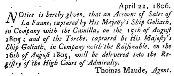
"Le Faune" was a French naval Le Cygne-class brig launched in 1804 to a design by François Pestel in 1803. She participated in the capture of HMS Blanche in July 1805. The Royal Navy captured Le Faune in August 1805. She was taken into service as HMS Fawn, but the last record of her dates to 1806. In 1807 the Royal Navy launched a new HMS Fawn.

Career:
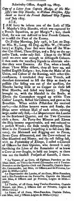
On 19 July 1805 Le Faune was part of a squadron of four vessels that captured HMS Blanche off Puerto Rico, three days after they had left Martinique. The other three were the 40-gun French frigate "Topaze", the 22-gun corvette "Department des Landes", and the 18-gun "Torche". Le Faune was under the command of Lieutenant Charles Brunet.

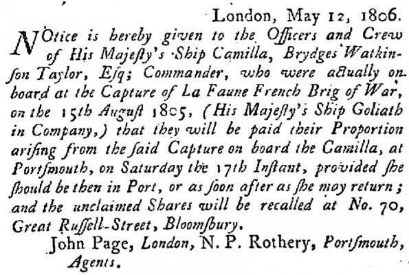
About one month later, Le Faune, still under the command of "enseigne de vaisseau" Brunet, was carrying dispatches from Fort-de-France to Saint-Nazaire via Saint-Martin-de-Ré. When she was southwest of Ouessant, on 15 August, she had the misfortune to encounter HMS Camilla.

Camilla chased Le Faune for nine hours before capturing her at Lat. 45 Deg. 18 Min. N. Long. 7 Deg. 36 Min.

The 74-gun, third rate HMS Goliath was in the Channel Fleet when she saw a sail to eastward and three sail to westward. Goliath sailed east and joined the chase, helping Camilla to capture Le Faune. Faune was armed with 16 guns and had on board 98 men. She also had on board as prisoners 22 men from HMS Blanche.

After Goliath helped Camilla capture Faune, she set off after the other three French vessels. Raisonnable joined Goliath and they were able to capture Torche, which the Royal Navy took into service as HMS Torch, but Topaze and Department-des-Landes escaped.

Captain Robert Barton of Goliath sent Le Faune into Portsmouth with Camilla. Barton reported that Le Faune was a new ship, on her first voyage, from Martinique, extremely fast, and would make a good addition to the Royal Navy.
The Royal Navy took Le Faune into service as HMS Fawn.

However, after 1806 there are no records of her.

Here below three articles fron the London Gazette describing some events where Le Faune was involved . .

post-1168-0-36568600-1414522149_thumb.jpg


post-1168-0-71601200-1414522164_thumb.jpg


post-1168-0-36587100-1414522169_thumb.jpg
 
Back
Top