• Ships of Scale has incorportated an extra level of security when you log In. Please follow on-screen prompts to acknowledge that you are not a robot via a "Check Box" or a "Pictorial Check Box Puzzle". This is needed due to higher level of AI Activity Security.
  • SUBSCRIBE TO SHIPS IN SCALE TODAY!

    The beloved Ships in Scale Magazine is back and charting a new course for 2026!
    Discover new skills, new techniques, and new inspirations in every issue.

    NOTE THAT OUR NEXT ISSUE WILL BE July/August 2026
  • Win a Free Custom Engraved Brass Coin!!!
    As a way to introduce our brass coins to the community, we will raffle off a free coin during the month of August. Follow link ABOVE for instructions for entering.

HMS Medea (28) (1778) 1/48 scratch build

Following on from yesterday's post about 3D printing. I have tried carving but with very little success and certainly nothing to add to my Medea.

However, my discoveries of the wonder of AI imaging are proving extremely profitable.

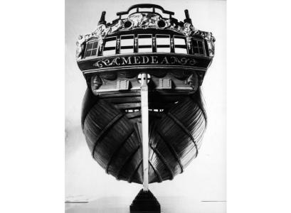
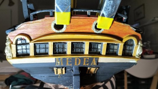
For instance, this is the best image of Medea's stern (from the 1778 model in Bristol Museum) that I could obtain.
Stern.png

As you can see it shows very sketchy detail.
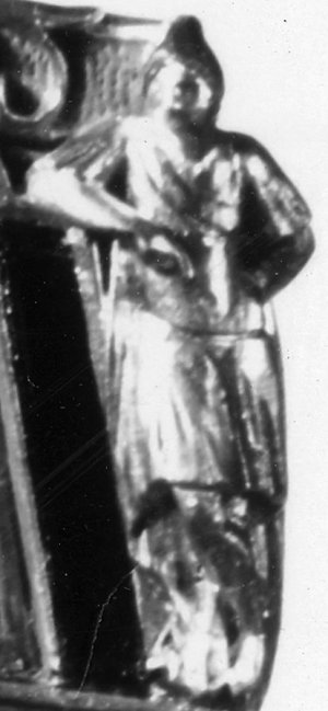
Tonight, in less than two hours, I cut the the image of the figure leaning on the shelf on the right hand side of the stern,

quarter figures_2.jpg

Then fed it into Makerworld MakerLab and chose 'make 3D from image'.

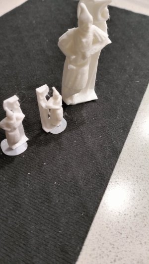
I wasn't expecting much but the file I received blew my mind. I printed it oversize just to see how much detail it had deduced and then printed the actual size for the model afterwards.

IMG20260715201705.jpg

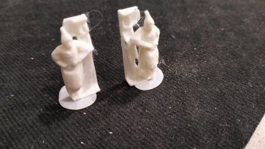
One model and a mirror image printed at the same time.
IMG20260715201723.jpg
With all the extra bits cut off, a cleanup and paint and they will do nicely.

At my current age and with ongoing health problems, I am going for broke now to get the job done, whether by my own skill or the help of technology.

More to come tomorrow night.
 
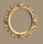
I searched the Internet for a suitably impressive image for the stern gun port carvings and settled on this one.


Screenshot 2026-07-16 173835.jpg

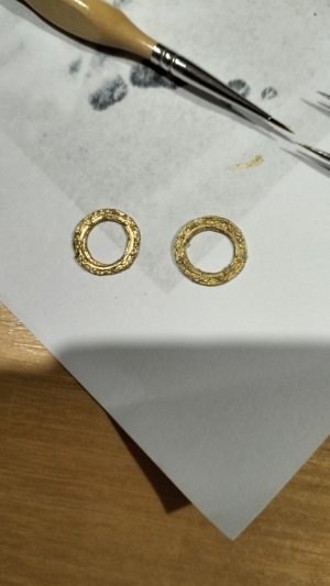
Then I printed two of them to size (18mm diameter) and, well, see for yourself.

IMG20260716174350.jpg

Once again, they will look okay on the build but the photo shows that it was hardly worth looking for a great master image!

And fitted

IMG20260716181005.jpg
 
Last edited:
The figurehead (Medea) was a challenge and I spent a lot of time trying to carve something reasonable, without success.

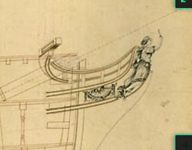
Fortunately, I knew from the plans in the Greenwich Maritime Museum that the figurehead was supposed to look something like this.
Screenshot 2022-12-01 093548.jpg

I then came across the book about Mr Hillhouse, the ship builder and subsequently the model he made of the ship in 1778 (now in the Bristol Museum). I obtained the following image in high resolution and worked from there with my new 3D printer.

J354[b].jpg

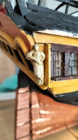
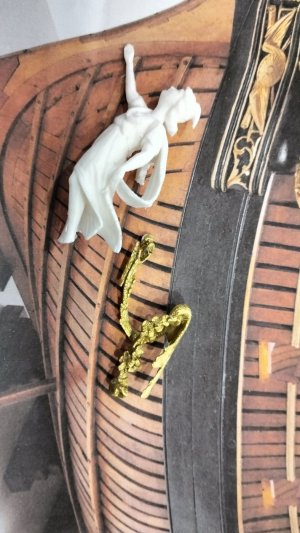
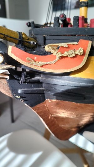
I ran a cut just of the figurehead through the AI software and then to my 3D printer and, after a couple of adjustments for exact size, I was able to print a good likeness. I did the same for the scroll work next to the head.

IMG20260707120406.jpg

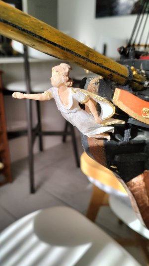
Painted and fitted. The dress is pearl white acrylic and the trim 14K gold acrylic.

IMG20260715084735.jpg
IMG20260715084742.jpg
I'll probably add a knife to the dreaded hand of Medea later.

The gilt panel below the scroll has proved to be problematic as it is curved and the AI software cannot get the proportions right yet. I'm probably going to have to spend some time learning how the manipulate images once I have the printer files. But that's for another time.
 
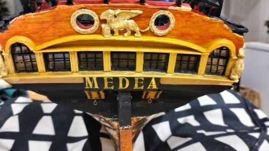
One last bit of decoration on the stern. From the black and white image I had available (see earlier post #443 above) it was almost impossible to discern any detail, but I decided the centre piece was a winged lion. I found a suitable image online and converted it to 3D for printing. Not a great success but carving it was beyond my skill level.


IMG20260717200506.jpg

Although Medea may have been fully decorated to builder Hillhouse's designs at launch, I have read that frigates of this vintage did not keep up the decorations during wartime. In fact Captain Gower disguised his ship as a merchant or storeship several times in India (1782-83) to avoid detection along the east coast and the less gold leaf decorations he had to hide, the better.

In the spirit of 'git er done', I now return to the much hated rigging. Some progress to show coming up next....
 
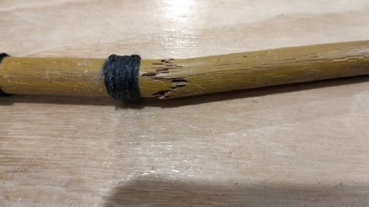
Firstly came the breaking of the Mizzen Mast 'close to the Quarter deck' as Gower described it. A nice splintered break, then temporarily repaired and taped until later. The top and some rigging added.

IMG20260719212215.jpg

IMG20260727141436.jpg

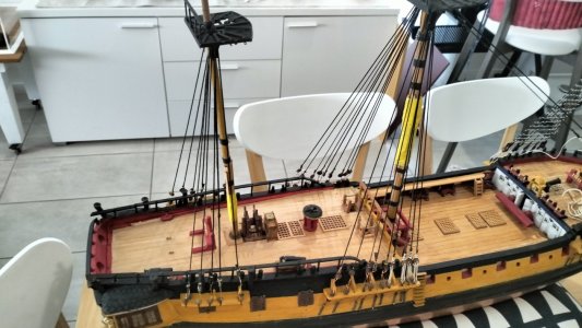
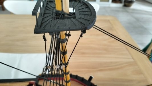
Due to my inability to feel thin thread (fingers worn out after 40 years farming and blacksmithing etc) I have resorted to using thin copper and brass wire to set up the standing rigging. I do the starboard side first, attempting to keep the alignment of the dead-eyes fairly level, then I add the opposite port dead-eye in the appropriate position and return to the starboard one to add the actual lashing.

From that description you will deduce that I don't try doing them in pairs on one side, then the other, any more. I did it with the foremast and it was a nightmare for me. For the Main and Mizzen I started with the starboard stay, ran it up and around the mast once and then anchored it on the port side. This way I can get a better result in keeping the starboard dead-eyes level and can make any adjustments I need to on the port side where the alignment won't be visible in the diorama.

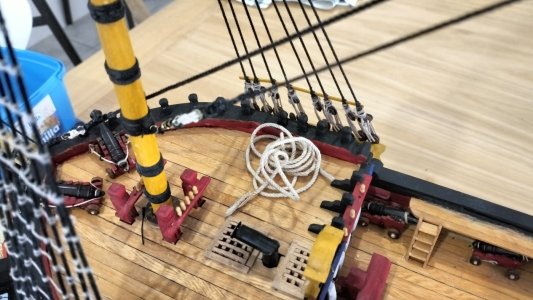
The next problem I had to face was that working on the Main standing rigging started to tilt it backwards, so I had to leave that and add the Main Stay and Preventer Stay. Which raised a further problem. I hadn't made provision for the bow loop of the main stay below the heads, so I had to carefully drill down through the grating to make a path on either side of the bowsprit.

The joys of winging it from step to step with no written guide to assist me. I think I sit and look at this model for as many hours as I work on it, trying to guess or calculate what might come next... The stay should have been in place several years ago, I think, but I considered it would have just been in the way while I worked on the deck furniture.

IMG20260727141553.jpg

Not a good image (there is wet glue on the lashings) but the stays work as they should - bracing the Main at vertical again.
Likewise, I haven't attempted the downward braces for the bowsprit yet as they will impede my lifting spot when I have to move the ship. I might regret that delay too, in time.

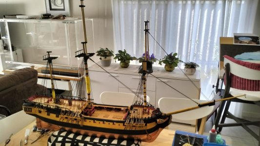
So this is where we are up to now. (And the African Violets are blooming again).

IMG20260727141359.jpg
 
Progress, slowly.
A little more rigging, then a side track to some more satisfying woodwork.

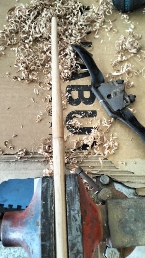
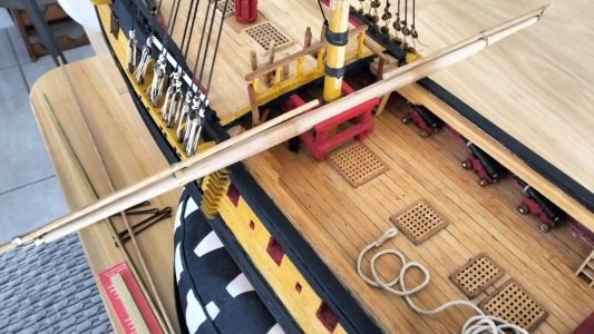
I decided to build the main yard and yard arms just to get a feel for how big this is all going to be.

It took me back many years to when I used to use a spokeshave and I thoroughly enjoyed the reunion.

IMG20260811121551.jpg

I know I could turn these on the lathe, or even with a drill, but I love the curls of timber coming off and the challenge of getting it even and round, with a straight taper.

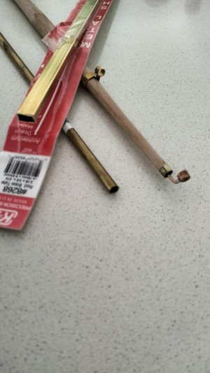
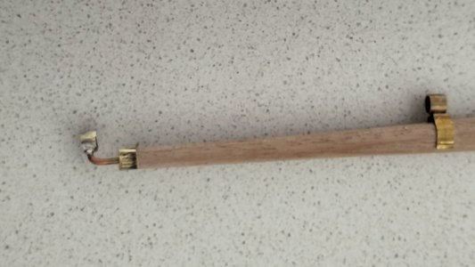
Next came the irons (brass in this case, which will be blackened).

I cut off small slices of round brass for the sleeves and then cut matching slices off a hollow rectangular bar.

IMG20260813112429.jpg
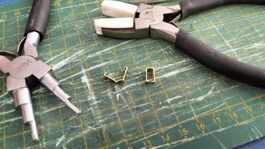
A slit was cut in one narrow end and the sides opened out.

IMG20260814143942.jpg

You can see that as I opened it out it created a convex surface which fitted the radius of the round bar. These were soldered together and fitted to the yard.

IMG20260813112540.jpg
IMG20260814142150.jpg

For the diorama, this main yard will be lowered (just before the main mast snapped) so this is pretty much where it will be lashed.

Next is the fore yard which will be in it's operational position on the mast.

Thanks for watching.
 
Well, one step forward and another back.

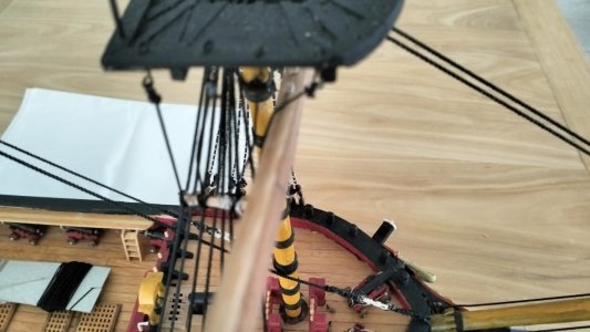
I'm not sure what parallel universe I was in when I fixed these futtock shrouds forward of the mast. But of course, as soon as I held up the yard against the mast I saw how stupid it was. So, I have to do some rearranging there. Fortunately I hadn't seized the rope ends or fitted the ratlines yet.

IMG20260817114827.jpg

IMG20260817114918.jpg

Sometimes my lack of experience builds things that are technically impossible to work in real life. ;)
 
Another side track in lieu of rigging

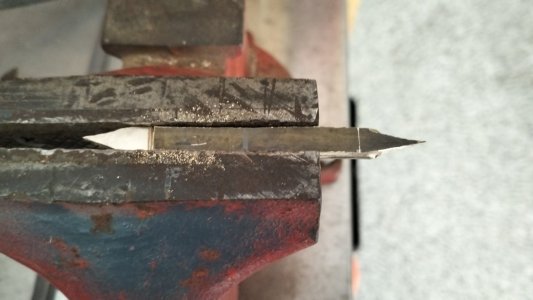
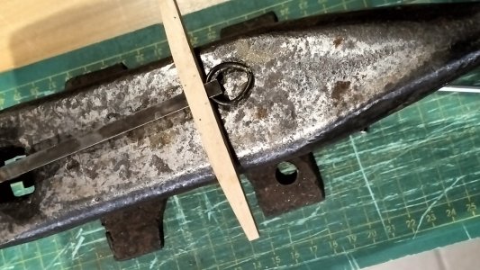
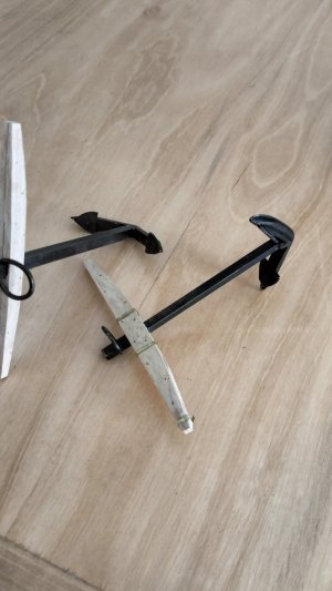
Using the same scrap brass as before (a strip of carpet edging) I spent a happy 6 hours making the second bower anchor.

Cut with my jeweller's saw and filed with small files.

IMG20260817163101.jpg

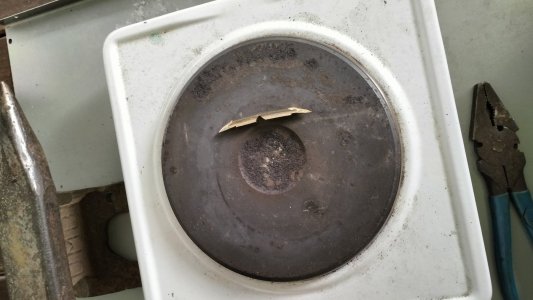
Preheated on the stove and then bent to 63 degrees using pliers and a small blow torch.

IMG20260818085210.jpg
IMG20260818134142.jpg


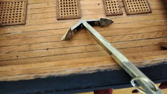
Fitted and soldered. The ring is scarf joined (just because it would have been originally and I used to do blacksmithing).


IMG20260818141656.jpg


IMG20260818162035.jpg
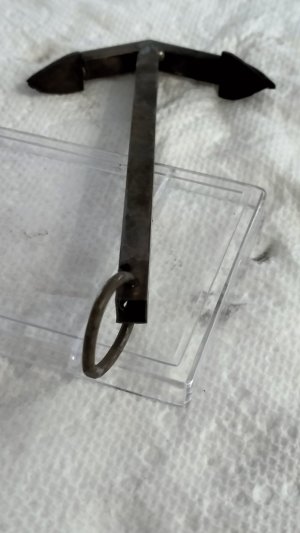
Blacked and stock fitted (PVA and brass wire nails .07mm)


IMG20260819083405.jpg

Historically, both these bower anchors were lost near Delgada, São Miguel Island, Azores, Portugal, five days after Medea was dis-masted in 1783. A huge swell forced Captain Gower to cut the cables and put to sea while his crew still continued completing the jury rig for main and mizzen masts.

Thanks for watching. Rigging continues, slowly.
 
Now that's some impressive metalworking, Ian! Way to go!
Thanks Paul.
Metal and wood I can generally handle. String, rope, blocks, seizing etc not so much.

I made the decision early on as you know, that I would do as much rigging as needed then throw most of it over the side with the main and mizzen masts. Someone commented on here at the time that it might take more work to do it wrong than to do it right. I think he was correct. I still have the struggle with materials I cannot feel which was my initial concern. Perhaps not so bad seeing I'm not trying to build a museum model. Cautious
 
I've been watching quite a few of Olha's wonderful videos about the restoration of Boreas and have picked up on a lot of technical details which the Enterprise class of frigate must have had as well.

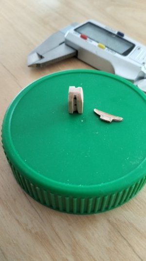
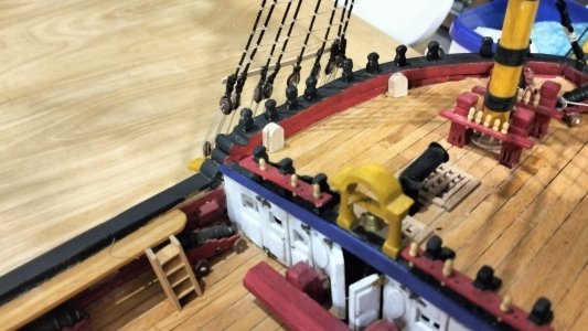
The sweep oar ports should have lids so I have done that.
IMG20260828142448.jpg

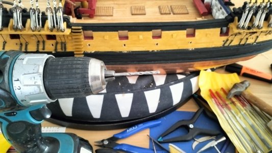
I never imagined I would take to my model with the Makita but the scuppers I so carefully did back several years ago were too small in scale (less than 3") so I drilled them out at 4mm (8")and inserted blackened brass rod.

This raised the next question - at what level on the hull should the gun deck scuppers drain? Unless they have a drop pipe they should drain at an equal distance below the level of the gun ports (and the deck). However, every model I have checked shows them discharging further down just above the wales. See my question at https://shipsofscale.com/sosforums/threads/position-of-scuppers.19990/

If anyone can give me a definitive answer I would appreciate it. It either means I will paint the black above the wales up to my present scupper position, or take them all out, move them lower and try to patch the holes.
 
Last edited:
Back
Top