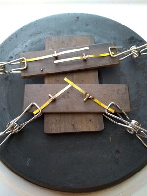
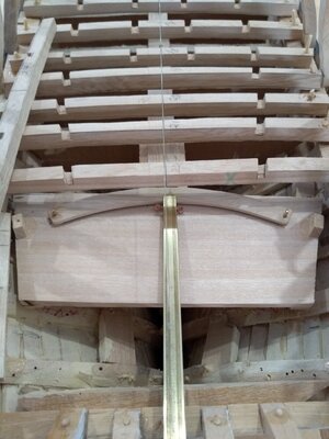
HMS Medea (28) (1778) 1/48 scratch build

Received the brass flat, rod and tube in the mail and began my first mini soldering attempt. It was completed successfully but took far too long due to pieces moving about while I applied the soldering iron. I have a blow torch but its flame is too violent for such small pieces. Here's the first pintle construction.

The three components - strap, barrel and pin.

IMG_20210818_101905455_HDR.jpg

Dry fitted.

IMG_20210818_103108625.jpg

Soldered and drilled but not cleaned up yet. The brass nails are 7mm x .7mm.

IMG_20210818_120811462.jpg

Cleaned up and dry fitted again. I have to wait now for the Birchwood Casey brass black to arrive before nailing to the rudder.

IMG_20210818_121349071.jpg


Next post - a different and (I think) better way of soldering these small parts.
 
Last edited:
Having an electric hot plate I use for heating bookbinding tools, I decided to give it a go for soldering these tiny brass parts.

I set them up on strips of thick brass which I know would generate the heat required as I do the same for bookbinding (it keeps the delicate border edges of the binding tools off the hot plate and allows me to lay them flat).

IMG_20210819_084223367_HDR.jpg

The barrel and pin pieces were carefully laid in the bend in the flats and small pieces of 60/40 Rosin Core Solder (1mm diameter) was laid above the joins.

IMG_20210819_085847704.jpg

When everything was balanced and in place I turned the heat up until the solder melted into the joints, then turned it off until the pegs were cool enough to hold and removed the pintles from the stove.

IMG_20210819_085857808.jpg

IMG_20210819_090523628.jpg

Four pintles completed in less time than the first one took yesterday.

IMG_20210819_144349034.jpg

I applied a drop of CA to the top of each pintle to ensure the pin was secure inside the tube. Very happy with this and I will only improve as the build progresses.
 

Attachments

  • IMG_20210819_090523628.jpg
    IMG_20210819_090523628.jpg
    212.7 KB · Views: 5
Without any written directions and only sketchy plans, the finer details of this scratch build are getting tricky. Below the gun deck has been pretty much bashed to get things assembled and progress to the parts of the ship which will be on display.

I've spent several days trying to work out how the Medea rudder was operated and finally came across some helpful images on SOS which showed, for instance, the mechanism for the Victory rudder at Portsmouth. Matching that knowledge to the cross section and plan views of the Enterprise which I am working to, I came up with this....

First I made a plate to mount the steering arm and pulleys onto. The outer pulleys were drilled with a 2mm bit and reamed out with a needle file. A 1.5mm hole was drilled vertically and a copper wire pin inserted for the 'pulley' .
IMG_20210829_122030736_HDR.jpg

An arc to match the swing of the rudder arm was made with 1/16" jacaranda, two guide eyelets made with copper wire and the lot mounted on the plate and tested.
IMG_20210830_161417924.jpg

The rudder arm is made from a hollow brass section, with the sides cut out to fit the arc. I drilled through the walls to insert a wire with loops on each end for the steering rope.

IMG_20210830_161438455.jpg

IMG_20210830_161535398.jpg

IMG_20210830_161619916.jpg

IMG_20210830_161728202.jpg

Dry fitted to test and immediately discovered that I don't have much room to thread the rope from the steering wheel to the outer pulleys, but I'll cut away some surplus timber where the 23rd deck beam is to be mounted. I should then be able to thread it with a short copper wire hook and two sets of tweezers. Oh boy, I can't wait for that!!!


IMG_20210830_162536619.jpg

After measuring the arm to fit the rudder I cut two slots in the end. Tomorrow I will heat the brass and bend the two wide slots open to fit against the front of the rudder. The narrow side strips will become the straps along the side of the rudder and will be nailed.

IMG_20210830_171947708.jpg
 

Attachments

  • IMG_20210830_162411649.jpg
    IMG_20210830_162411649.jpg
    198.4 KB · Views: 5
Last week I completed most of the gun deck beams. Still a bit of sanding to do to get the height aligned correctly but I've left that until after I get the rudder installed below that deck.

IMG_20210828_144740808_HDR.jpg

IMG_20210828_144753708.jpg

I decided to notch right across the beams so that I can use longer stringers, rather than use short pieces between beams. Not strictly according to the plans but it should get the job done and will be out of sight once the planking goes down. I've also inserted square posts beneath a few beams to help support the deck weight, not that it will be much.

Without written instructions to guide me I find I spend just as much time pondering what to do next as I do actually making it. But I set myself the task to scratch build with my own timber and I'm really enjoying the challenge.
 
Thanks for posting the detailed and "new" innovation for soldering the rudder pins. Rudder is still to come on my scratch build and these ideas will help immensely! Great work and ingenuity!
No worries. Thanks for watching. Not everything I try works out of course. It's all a steep learning curve for me but the journey is worth the effort.
Good luck with your build. I admire your carving skill and will learn from it when the time comes to carve 'Medea'.
 
The tiller assembly dry fitted and working.

IMG_20210831_164524271.jpg

IMG_20210831_164547264.jpg

IMG_20210901_170511227.jpg

I used two bamboo treenails loosely fitted to align the tiller frame. I just need to move it 1mm towards the stern, bore new treenail holes and it will be glued and nailed in place.

Another piece of the stern frame broken off in the process :mad:. I'll have to insert a small wire inside it this time to hold it in place. Using glue didn't hold as I kept making contact with it.....Clumsy....
 
A long day yesterday. As well as the tiller fitting I also laid, sanded and glued in the deck stringers. One bearer is out of alignment but I will pack it with 1/32" timber I have ready for the job.

My attempts to cut the planking at 1/4" x 1/16" so far have been rough so I have to work out some better method. I made a 'saw bench' for my Dremel 3001 but it doesn't seem to have the grunt to drive the mini saw blades. The Sawstop saw at the community workshop wastes more wood than I end up with and the planer/thicknesser doesn't cut down to 1/16".

IMG_20210901_165545312.jpg
 
One thing I have determined is, if it isn't right, go back and correct it. I made a mistake with one cross piece of the stern frame and it did not have the required curve or the extensions for mounting the quarter galleries. So I took to it with a saw and chisel and made it good.

IMG_20210906_123007960.jpg


IMG_20210906_124954176.jpg

IMG_20210906_143744261_HDR.jpg

Perhaps the image quality doesn't show it clearly but the spaces for the windows are now in the right proportions.
 
Looking back over my build log, it has taken a very long time to get to this point....Thank you to anyone still reading along.

I recently formed the stern piece, using 1/8" jacaranda. I cut it out as near as comfortable with the scroll saw and then sanded, chiseled and filed it into its final shape. With the grain running across the piece it bends very nicely to the contour of the stern.

IMG_20210911_141958430.jpg

IMG_20210911_142317895.jpg

IMG_20210918_120541147.jpg

I'm just waiting for delivery of my Micro Wood Profile Scrapers so that I can form the colonnades before gluing onto the frames.
 
Back
Top