HMS Ontario 1780 scale 1:32 POB full version

look in at facts the Royal George was built in a English ship yard, taken apart and reassembled on lake Champlain in 1777
Royal George 1777
tonnage 384
keel 77' 9"
deck 96' 6"
breadth 30'6"
hold10'
20- 12 pounds
6- 6 pounders
10 swivel guns

three years later the same Master shipwright built the Ontario

tonnage 226
keel 64" 8'
deck 80'
breadth 25' 4"
hold 9"

16- 6 pounds
6- 4 pound

these two ships were built 3 year apart no doubt the RG was built as a war ship the Ontario as an armed transport. both ships were classed as armed transports.

a master shipwright when faced with having to build a ship fast and in the wilds of North America would not take chances on unproven designs. I think Coleman used the R.G. design and construction as a model to build the Ontario as smaller version.
 
Thank you Dave for sharing this,my plan is to build a POB and hopefully a cross section similar like the Bomb Vessel Grenado from MSB,I am not sure if I need such a detailed plans for that.
 
Hello Zoltan

Your HMS Ontario is very close in size to that of the HMS Bounty she sure will be a great ship to build. My Bounty was on the 1:60 scale and came out with an overhaul length of 30.5". or 77.5 CM. and I thought that she was a nice scale to work at. But a scale of 1:48 sure would give you much more room to add a lot more very fine detail, but then again do you have the room to display a larger ship, that is the question, ENJOY

Regards Canoe21 { Lawrence }
 
Hello Lawrence,luckily I have room for larger models,not that I am going to build a lot of them. :D
 
shipwright101 said:
Both the Ontario and the Royal George were built by the same master shipwright Jonathan Coleman. He was a trained shipwright and served in the Royal yards in England. Both ships seem to have the same style and I would think the same construction. Both were armed transports built for lake service, but it seems the design of the R.G. has a slightly more bend towards a fighting ship a little lower profile and a third mast. Sterns and body plans look very close. I have CAD drawings of both ships in my archives than can be used for plank on frame or plank on bulkhead models. I am more than willing to share whatever research material and drawings I have.

Hello Dave,my knowledge sbout CAD is less than nothing ,if you share with me those plans how can I use them,I assume that probably there is an option for print them out.

Thanks ,Zoltan
 
Hello Dave,my knowledge about CAD is less than nothing ,if you share with me those plans how can I use them,I assume that probably there is an option for print them out.

the plans are not "modeling" plans so your right if you don't know CAD then you would not be able to develop them into anything usable.


A plank on bulkhead model would be no problem to set up in cad, I will work up a set of bulkhead drawings and post them. Anything I post is public domain so anyone can use them.
 
Thanks Dave for your response, I am planning to build a Pob full ship and maybe a Pof cross section, but if I have to use Cad that might be out of sight.For the Pof cross section I would need a set of plan like the MSB 's Bomb Vessel cross section plan,and don't see that possible for me.
 
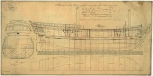
looking at the drawing J Coleman did not draw hull lines only a sheer line and a deck line and the rising line at the bottom.

He did draw a nice bodyplan so bulkheads can be drawn from the bodylines, but their locations fall into gun ports. You will need to have bulkheads only to the lower deck and build the upper works separate. To build a bulkhead hull so the bulkheads miss the gun ports and run all the way up to the cap rail would be a better way to construct the hull.

Ontario.jpeg
 
Last edited by a moderator:
Thanks Dave for your time,the second hull image shows the actual bulkheads position or this still under process because I see the red lines are right besides the gunports??.
 
Take bulkhead number 14 in the upper drawing it is in the original location drawn on the plans
if you shift number 14 so it falls at the location of the gun port in the lower drawing it will change shape. The red line is the upper original location and the black line is the new location at the gun port.


as a result of moving the bodylines from the top drawing to the locations in the bottom drawing renders the original bodyplan useless. so you can not do what canoe21 did in his build by cutting up the bodyplan to make templates for the bulkheads. If you don't shift the locations of the bodylines the tops of the bulkheads will fall in the gun ports.

http://www.shipsofscale.com/sosforums/viewtopic.php?f=59&t=1221&start=10

when planning the project you have 2 choices either move all the bulkheads so they line up with the gun ports like I did in the lower drawing or build the hull in two sections. stop the bulkheads at the lower deck and build the upper section of the hull separate to match up with the gun ports. One issue with building the upper section separate is the fact the hull had some complex shapes to deal with. The line cutting through the bodyplan is the deck line, notice how the hull tumbles inward and then up, all along the hull this shape changes. to build this part of the hull separate will require a strong solid structure in order to get the need shape of the hull.
 
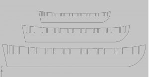
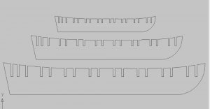
first is 1/4 scale 20 inch hull
second 3/8 scale 30 inch hull
third 1/2 inch scale 40 inch hull
at mid ship
6 inch wide x 4 inch high at 1/4 scale

9 inches wide x 6 inches high at 3/8 scale

12 inches wide x 8 inches high at 1/2 scale

scale.JPG
 
Last edited by a moderator:
Back
Top