-

Win a Free Custom Engraved Brass Coin!!!
As a way to introduce our brass coins to the community, we will raffle off a free coin during the month of August. Follow link ABOVE for instructions for entering.
-

PRE-ORDER SHIPS IN SCALE TODAY!
The beloved Ships in Scale Magazine is back and charting a new course for 2026!
Discover new skills, new techniques, and new inspirations in every issue.
NOTE THAT OUR FIRST ISSUE WILL BE JAN/FEB 2026
You are using an out of date browser. It may not display this or other websites correctly.
You should upgrade or use an alternative browser.
You should upgrade or use an alternative browser.
HMS Pegasus 1776 Amati Victory series
- Thread starter mallacoota
- Start date
- Watchers 10
-
- Tags
- amati pegasus victory models
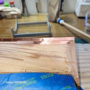
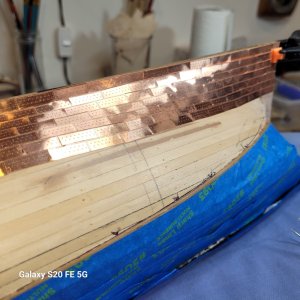
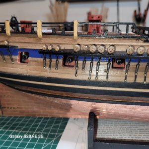
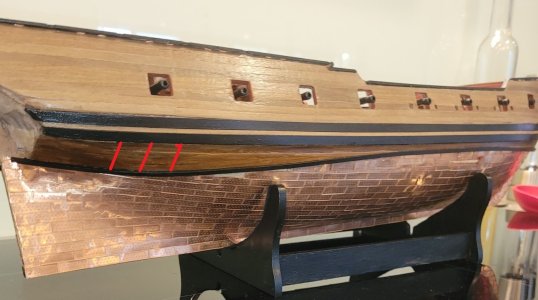
Good looking copper sheathing
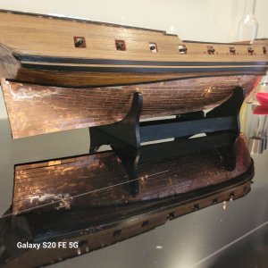
I wonder only about this relatively bigger distance - Is the upper end of the coppering representing the waterline?
Or is it the strange perspective making this? Directly from the sideview the upper end would be a horizontal line - but sometimes, especially on curved surfaces the eye is showing something different......
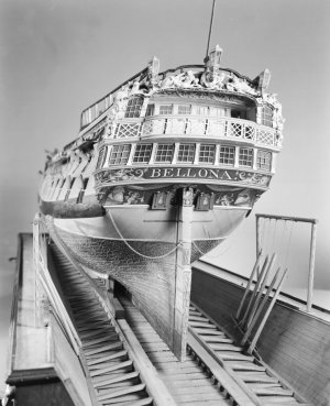
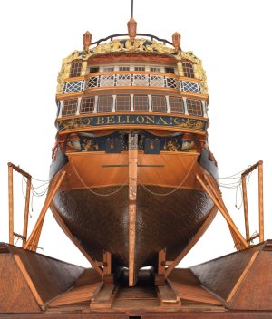
A contemporary model in the NMM of the HMS Bellona
I wonder only about this relatively bigger distance - Is the upper end of the coppering representing the waterline?
Or is it the strange perspective making this? Directly from the sideview the upper end would be a horizontal line - but sometimes, especially on curved surfaces the eye is showing something different......

A contemporary model in the NMM of the HMS Bellona


Last edited:
Thanks Allan... it is actually easier to overlap than to butt joint as it turns out in practice.
Good looking copper sheathing
I wonder only about this relatively bigger distance - Is the upper end of the coppering representing the waterline?
Or is it the strange perspective making this? Directly from the sideview the upper end would be a horizontal line - but sometimes, especially on curved surfaces the eye is showing something different......
View attachment 471891
A contemporary model in the NMM of the HMS Bellona
View attachment 471889 View attachment 471890
It is the perspective. Strraight by eye, by plans, and by waterline marker
Last edited:
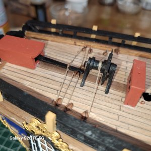
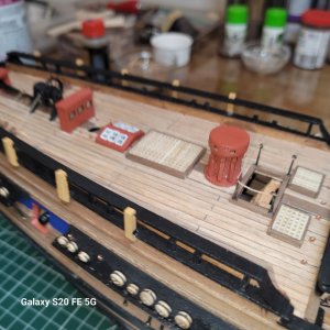
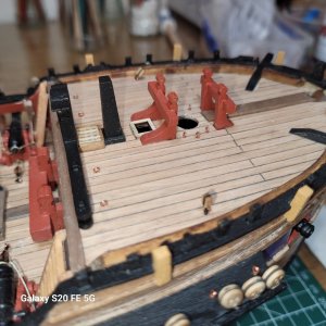
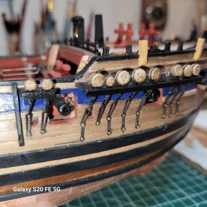
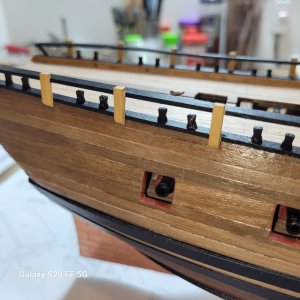
Still some detail to go in here but some various progress...the quarterdeck rail cappings dont stand on those posts, they stand on the sides of the swivel gun posts which makes them difficult to install in place so I made the rails and posts offline and painted them. Worked out well that way. Havent decided yet whether I will rig the main guns any further...probably not, but i should rig forward hauling tackle.
Just to anticipate any thoughts on my use of a king plank in the deck. It is a bit of kit bashing by me for appearance. In actual fact ships of the time often had two "major" planks one running down each side of the hatches and companionways where a straight run was possible for strength, rather than down the centreline which offered no rigidity with all the hatch interruptions. They were always looking fof longitudinal rigidity because hogging was a major issue. I might do that the right way on the next boat, makes more sense.
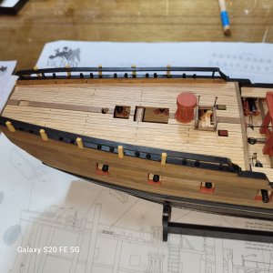
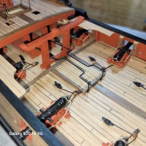
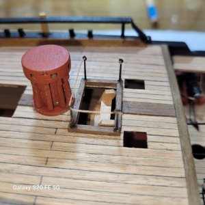
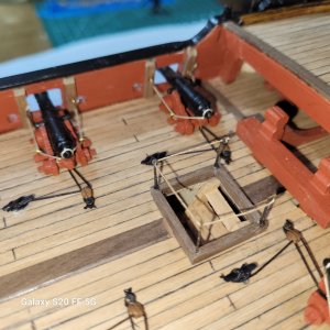
Just to anticipate any thoughts on my use of a king plank in the deck. It is a bit of kit bashing by me for appearance. In actual fact ships of the time often had two "major" planks one running down each side of the hatches and companionways where a straight run was possible for strength, rather than down the centreline which offered no rigidity with all the hatch interruptions. They were always looking fof longitudinal rigidity because hogging was a major issue. I might do that the right way on the next boat, makes more sense.


Last edited:
Humble Pie eating time.... oooops...Uwek you were right and I was wrong. My waterline was crazy...I dont remember being red wine affected when I did it but something went wrong. In my defence it is a really tricky waterline to bring to the stern as the aft is so undercut. I have it pretty right now I think. Thanks for the heads up. 


This came up the other day on another build log. It was asked if the coppering was started at the keel or at the water line. I would not be surprised at all if some ships were coppered from the keel upwards and others from the water line down, both of which would have had overlapping. I had never given this any thought before the question was raised and did some digging but found nothing other than the drawings by Peter Goodwin. If Goodwin is correct in The Construction and Fitting of the English Man of War, page 225 it would have started from the waterline and worked down, but again, I have no idea if this was the general method followed or just his supposition. It seems it would be easier to keep things square if starting at the keel, but...........
Allan
Allan
Last edited:
AllanThis came up the other day on another build log. It was asked if the coppering was started at the keel or at the water line. I would not be surprised at all if some ships were coppered from the keel upwards and others from the water line down, both of which would have had overlapping. I had never gave this any thought before the question was raised and did some digging but found nothing other than the drawings by Peter Goodwin. If Goodwin is correct in The Construction and Fitting of the English Man of War, page 225 it would have started from the waterline and worked down, but again, I have no idea if this was the general method followed or just his supposition. It seems it would be easier to keep things square if starting at the keel, but...........
Allan
I cant see how you could satisfactorily overlap the plates starting at the top. Just thiunk of the plates as clinker planks, they must overlap from above and doing this with a top down approach would seem impossible.
You may be right Mallacoota, and perhaps both top to bottom and bottom to top were used on different ships and eras. The only information I could find was from Goodwin along with a few photos which are below. Current plating on Cutty Sark was laid down top to bottom but this may not be how she was originally sheathed. If anyone has more information based on contemporary sources that would be great. Looking at the original coppering plans for Imogene at RMG it is not possible to tell if the overlap is from the top down or the keel up. It does give one an idea of the lay of the coppering though, so a useful drawing. For the Edwin Fox 1853, in the first photo below, plating was laid down water line to keel. I am not sure what ship is pictured in the second photo but the plating was installed from the water line down as can be seen by the overlap which matches the Goodwin drawings.Just thiunk of the plates as clinker planks,
Allan
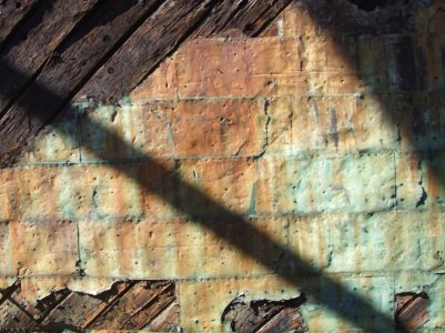
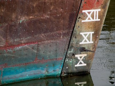
Imogene plating plans

a
Well the photos dont lie but it makes no sense to me. Why would you create an opportunity for the water to run inside the plates under gravity..? you would be relying 100% on whatever sealant you used.
I don't think gravity plays a part when the hull is in the water. It is not like rain flowing down a roof and overlapping of shingles from the bottom up makes sense. When a ship is in the water it displaces a volume of water equal to its own weight. This displaced water then exerts an upward force on the ship, buoyancy, which opposes the downward force of gravity on the ship.
Allan
Allan
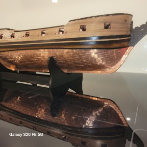
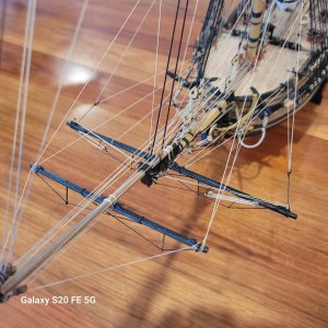
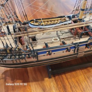
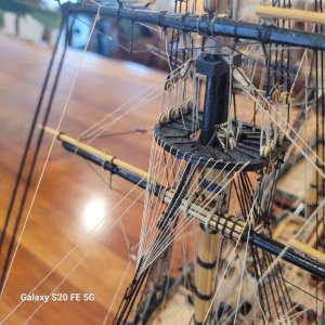
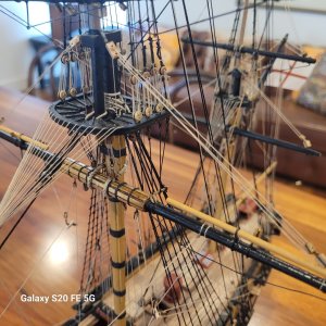
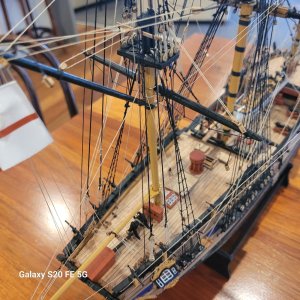
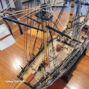
finished and launched...not my most enjoyable build but chose it to get experience at copper and crows feet rigging...did both of thos because parts left out.e. Happy with how it turned out , I am challeneged enough without the errors in the plans and some rigging aspects completely confusing because of omissions...whatever. I have been an Amati fan for a while but not so much this time. Will be interesting to compare with Occre Montanes when I start it. I am intending to attempt a scratch build of a Shetlad Yoal so might do a little of that before starting Montanes.
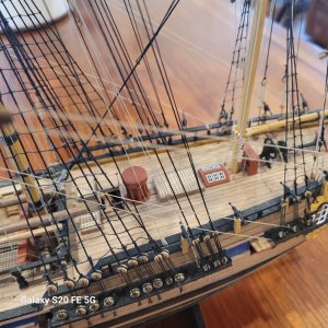
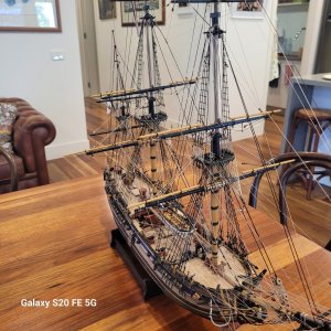
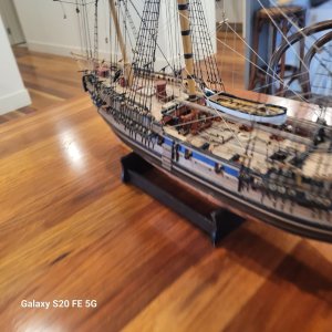
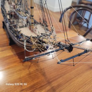
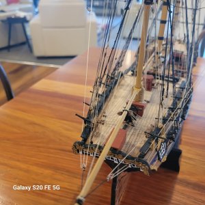
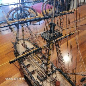


Awesome, that’s a real showpiece.
thank you kindly Bryian


