The gratings used are about 0.7mm. Better too small than too large I reckon. Other items which are typically oversized are planking widths, rigging blocks, line diameters, and ESPECIALLY belaying pins. If I had one of the models belaying pins enlarged to 1:1 scale, I could use it to hit a home run on the baseball field. I use the Falkonet belaying pins imported from Russia, because like many other Russian model ship accessories, they are the BEST.Kurt, you are right. On most models, the cell size on the gratings does not correspond to scale. In my construction according to Victory, I showed a comparison of the gratings from the set with what should be in scale. Life size cell size 3 inches. Convert to your scale and get your size. On my Victory in 84 scale, the cell size was 0.9 mm. If you have a model in 72 scale, then the cell is 1.05 mm. Can be rounded up to 1 mm.
-

Win a Free Custom Engraved Brass Coin!!!
As a way to introduce our brass coins to the community, we will raffle off a free coin during the month of August. Follow link ABOVE for instructions for entering.
-

PRE-ORDER SHIPS IN SCALE TODAY!
The beloved Ships in Scale Magazine is back and charting a new course for 2026!
Discover new skills, new techniques, and new inspirations in every issue.
NOTE THAT OUR FIRST ISSUE WILL BE JAN/FEB 2026
You are using an out of date browser. It may not display this or other websites correctly.
You should upgrade or use an alternative browser.
You should upgrade or use an alternative browser.
HMS Sovereign of the Seas - Bashing DeAgostini Beyond Believable Boundaries
- Thread starter DARIVS ARCHITECTVS
- Start date
- Watchers 105
Wanna trade? I'll rig your guns if you do my ratlines!I love your work Kurt! As an interesting aside - rigging cannons has thus far been the part of the build that I have liked the least! I would rather do ratlines for days than trying to get the blasted hooks to stay on the eyebolts.
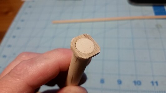
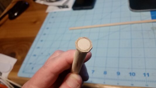
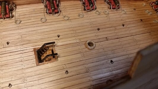
The wedges and coats for the main mast and mizzen mast were completed.
Sand the part making square sides.
Sand the corners to make an octagon.
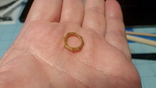
Round over to edges and draw seam lines with pencil.
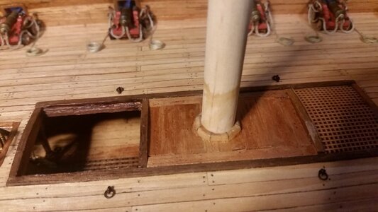
Main mast wedges and coat installed
Done!
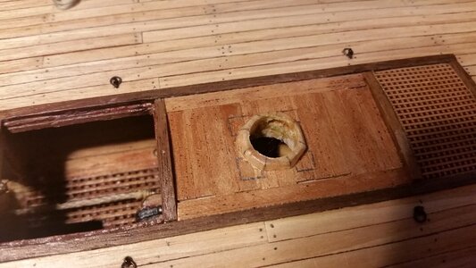
Test fit mizzen wedges and coat. Timbers need to be placed under this area before this part is glued to the deck.
Sand the part making square sides.

Sand the corners to make an octagon.

Round over to edges and draw seam lines with pencil.

Main mast wedges and coat installed

Done!

Test fit mizzen wedges and coat. Timbers need to be placed under this area before this part is glued to the deck.

- Joined
- Aug 8, 2019
- Messages
- 5,582
- Points
- 738

No, Paul is not to blame. I just wanted to show how bad it is to grow up in the Netherlands. You don't have to hear this song as a Dutchman. Seeing a yellow parakeet makes you hear that harmonica all day long. Even talking about it..... TadadadadadDAM, TadadadadadDAM tatatatat tatataDAM! All the Dutchies knowThanks. You've succeeded where hundreds have failed in scarring my brain for life. Did Paul pay you to do that?!
- Joined
- Aug 8, 2019
- Messages
- 5,582
- Points
- 738

This tiny collar looks real good. Well doneThe wedges and coats for the main mast and mizzen mast were completed.
Sand the part making square sides.
View attachment 307860
Sand the corners to make an octagon.
View attachment 307861
Round over to edges and draw seam lines with pencil.
View attachment 307862
Main mast wedges and coat installed
View attachment 307863
Done!
View attachment 307864
Test fit mizzen wedges and coat. Timbers need to be placed under this area before this part is glued to the deck.
View attachment 307865
Wow... We only have to hear that song at wedding receptions. You Dutchmen must be going out of you minds.No, Paul is not to blame. I just wanted to show how bad it is to grow up in the Netherlands. You don't have to hear this song as a Dutchman. Seeing a yellow parakeet makes you hear that harmonica all day long. Even talking about it..... TadadadadadDAM, TadadadadadDAM tatatatat tatataDAM! All the Dutchies know
It just occurred to me that I almost missed a very important step as described by Charles Aldritch: "The rudder head and tiller are always just under the middle deck on a three decker". That means that the tiller of the rudder must be under the middle gun deck, near the overhead of the lower gun deck. I have not made an opening in the hull for the rudder tiller yet, since the hull exterior is not finished. However, since the lower gun deck is no longer accessible, now is the last chance to install the tiller by boring a hole in the transom, and installing the whipstaff on the middle gun deck. It also occurred to me that my reference to the space beneath the lower gun deck as the "orlop" deck was incorrect. On three deck ships before 1650, the lower gun deck IS CALLED THE ORLOP DECK, and the deck below that is nothing more than a series of platforms at slightly varying heights making up the hold, anchor cable storage spaces, and other spaces.
So... time to get clever again. The thing to do is bore the hole for the tiller in the stern, make a tiller, create a low steering platform on the middle gun deck, drill a hole in that for the whipstaff. The forward end tiller will have a rotating cylinder of sorts on the end with a hole in the side of it to accept the lower end of the whipstaff. With a flashlight, I will have to insert the tiller, from the stern, and simultaneously insert the whipstaff from the top, and with a bit of glue on the end of the whipstaff, glue it to the rotating part on the tiller. Then comes the fun part. There is a transverse beam that the forward end of the tiller rides on for support. This beam should have been installed while the lower gun deck was exposed. OOPS. So, all I have to do is drill two holes in the hull at the correct height, and insert a stick of cherry or walnut through the hull, just beneath the tiller, but fat enough below the middle gun deck support structure above so that the tiller can move freely between them, and glued the ends of this beam to the hull. Trim off the excess beam sticking out of the hull on either side and make them flush, and let the finish layer of planking hide the whole thing. Easy as pie, right? You gotta love model building gymnastics.
The rudder, tiller and whipstaff will actually function if all goes according to plan. Glad I caught this oversight before it was too late, or there would be no whipstaff to steer the ship! McKay placed his tiller and whipstaff each one deck too high, which is not correct for this type of ship.
It certainly pays to stand back and review your work now and again so nothing is missed!
Last edited:
As they say, just in the nick of time. Will you be able to assess the elevation at which to drill the opening for the transverse tiller support beam with good enough accuracy?
You're MAD! MAD I say!!!It just occurred to me that I almost missed a very important step as described by Charles Aldritch: "The rudder head and tiller are always just under the middle deck on a three decker". That means that the tiller of the rudder must be under the middle gun deck, near the overhead of the lower gun deck. I have not made an opening in the hull for the rudder tiller yet, since the hull exterior is not finished. However, since the lower gun deck is no longer accessible, now is the last chance to install the tiller by boring a hole in the transom, and installing the whipstaff on the middle gun deck. It also occurred to me that my reference to the space beneath the lower gun deck as the "orlop" deck was incorrect. On three deck ships before 1650, the lower gun deck IS CALLED THE ORLOP DECK, and the deck below that is nothing more than a series of platforms at slightly varying heights making up the hold, anchor cable storage spaces, and other spaces.
So... time to get clever again. The thing to do is bore the hole for the tiller in the stern, make a tiller, create a low steering platform on the middle gun deck, drill a hole in that for the whipstaff. The forward end tiller will have a rotating cylinder of sorts on the end with a hole in the side of it to accept the lower end of the whipstaff. With a flashlight, I will have to insert the tiller, from the stern, and simultaneously insert the whipstaff from the top, and with a bit of glue on the end of the whipstaff, glue it to the rotating part on the tiller. Then comes the fun part. There is a transverse beam that the forward end of the tiller rides on for support. This beam should have been installed while the lower gun deck was exposed. OOPS. So, all I have to do is drill two holes in the hull at the correct height, and insert a stick of cherry or walnut through the hull, just beneath the tiller, but fat enough below the middle gun deck support structure above so that the tiller can move freely between them, and glued the ends of this beam to the hull. Trim off the excess beam sticking out of the hull on either side and make them flush, and let the finish layer of planking hide the whole thing. Easy as pie, right? You gotta love model building gymnastics.
The rudder, tiller and whipstaff will actually function if all goes according to plan. Glad I caught this oversight before it was too late, or there would be no whipstaff to steer the ship! McKay placed his tiller and whipstaff each one deck too high, which is not correct for this type of ship.
It certainly pays to stand back and review your work now and again so nothing is missed!
Last edited:
Or you could just tear out any intervening deck or other obstacles...It just occurred to me that I almost missed a very important step as described by Charles Aldritch: "The rudder head and tiller are always just under the middle deck on a three decker". That means that the tiller of the rudder must be under the middle gun deck, near the overhead of the lower gun deck. I have not made an opening in the hull for the rudder tiller yet, since the hull exterior is not finished. However, since the lower gun deck is no longer accessible, now is the last chance to install the tiller by boring a hole in the transom, and installing the whipstaff on the middle gun deck. It also occurred to me that my reference to the space beneath the lower gun deck as the "orlop" deck was incorrect. On three deck ships before 1650, the lower gun deck IS CALLED THE ORLOP DECK, and the deck below that is nothing more than a series of platforms at slightly varying heights making up the hold, anchor cable storage spaces, and other spaces.
So... time to get clever again. The thing to do is bore the hole for the tiller in the stern, make a tiller, create a low steering platform on the middle gun deck, drill a hole in that for the whipstaff. The forward end tiller will have a rotating cylinder of sorts on the end with a hole in the side of it to accept the lower end of the whipstaff. With a flashlight, I will have to insert the tiller, from the stern, and simultaneously insert the whipstaff from the top, and with a bit of glue on the end of the whipstaff, glue it to the rotating part on the tiller. Then comes the fun part. There is a transverse beam that the forward end of the tiller rides on for support. This beam should have been installed while the lower gun deck was exposed. OOPS. So, all I have to do is drill two holes in the hull at the correct height, and insert a stick of cherry or walnut through the hull, just beneath the tiller, but fat enough below the middle gun deck support structure above so that the tiller can move freely between them, and glued the ends of this beam to the hull. Trim off the excess beam sticking out of the hull on either side and make them flush, and let the finish layer of planking hide the whole thing. Easy as pie, right? You gotta love model building gymnastics.
The rudder, tiller and whipstaff will actually function if all goes according to plan. Glad I caught this oversight before it was too late, or there would be no whipstaff to steer the ship! McKay placed his tiller and whipstaff each one deck too high, which is not correct for this type of ship.
It certainly pays to stand back and review your work now and again so nothing is missed!
Cute V,Or you could just tear out any intervening deck or other obstacles...
I should have used a sarcasm emoji. Now I'mCute V,but the idea, despite what you may believe from earlier posts, is to minimize damage. Making new seams in the deck would ruin its appearance. Holes in the hull are patchable and leave no trace at this stage.

Easily. The gun ports indicate where the deck is. You go about 15mm down from the lower edge of the gun port, and that should be were the bottom edge of the tiller should be. Here's the process. The holes in the hull are locate to the best estimate. The holes are not drilled at full size. Instead you drill a tiny hole and run a stiff steel wire through the hull and see how high the tiller is when resting on the wire. If the holes in the hull are too high or low, they can be adjusted. Adjust the height of the holes by filing the size of holes to the full cross section of the beam up or down as necessary to adjust its position. This way, you don't have to be perfect guessing where the holes have to be, just close, within the vertical thickness of the crossbeam.As they say, just in the nick of time. Will you be able to assess the elevation at which to drill the opening for the transverse tiller support beam with good enough accuracy?
Last edited:
And..?You're MAD! MAD I say!!!
Outstanding!Easily. The gun ports indicate where the deck is. You go about 15mm down from the lower edge of the gun port, and that should be were the bottom edge of the tiller should be. Here's the process. The holes in the hull are locate to the best estimate. The holes are not drilled at full size. Instead you drill a tiny hole and run a stiff steel wire trough the hull and see how high the tiller is when resting on the wire. If the holes in the hull are too high or low, they can be adjusted. Adjust the height of the holes by filing the size of holes to the full cross section of the beam up or down as necessary to adjust its position. This way, you don't have to be perfect guessing where the holes have to be, just close, within the vertical thickness of the crossbeam.
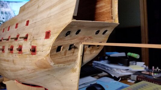
Construction of the tiller, whipstaff, and the arched tiller support were made after taking measurements off the hull. The tiller hole was cut first in the transom. It is lower than depicted in the Lely painting, since that painting was incorrect with respect to the height of the rudder and tiller location. A stick of 3x3mm walnut wood was used to check the position of the hole. The forward end of the stick, which will be made into the tiller, rests on the bottom of the overhead deck beam. Since the stock is near horizontal, the hole's vertical position is correct. AS long as I'm going through the trouble of making the whipstaff, it may as well be made to function like a real one. Movement of the rudder with your fingers should allow one to see the free movement of the whipstaff's angle and it's extension while viewing through the last gun port on the middle gun deck.
The length of the tiller was estimated, and I believe I can get an arc for the tiller of about +/- 30-35 degrees for the rudder. A long stick of 3x3mm cherry wood was soaked in water and bent onto an arc. This will support the bottom of the tiller, and be installed through holes to be cut in the hull later. It will be about 3mm below the overhead beam, and the tiller will be able to swing on top of this arc and below the beam overhead with a small clearance.
The whip staff was fashion by a stick walnut with a paddle shape containing the hole glued to the end of the staff. A length of 18 gauge brass wire with and end cap made from wood will hold the whipstaff to the tiller, and the end of the whipstaff can slide on the the length of wire to account for the fore-aft movement of the end of the tiller due to the arc of its motion.
But first, here my Bengal kitty Leopold kicking back with me after a hard day's work.

The tiller hole is rectangular, and was filed wider on the inside to allow space for the tiller to swing.
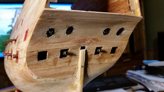
Test fitting of a stick to see how high the overhead beams are, determine the tiller length and arc of travel.
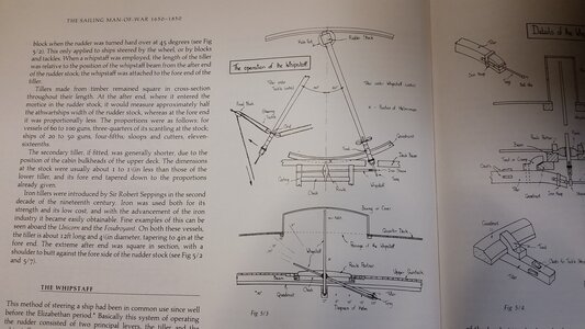
Below is an excerpt showing the basic plan in making the tiller and whipstaff. The rowle and deck fittings will be made later. The arched beam will act as the quadrant, but the tiller will ride above it, not below. This simplification was made because of the late installation and lack of access at this stage in the build.
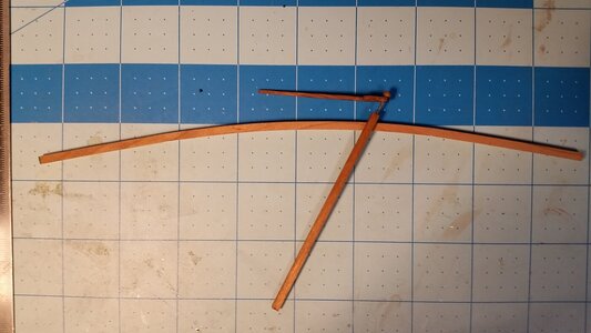
Top view of the parts. The rudder will be at the bottom. The whipstaff is close to where it would be with full left rudder. Because of the height of the whipstaff, the steering compartment will have to extend upward into the upper gun deck.
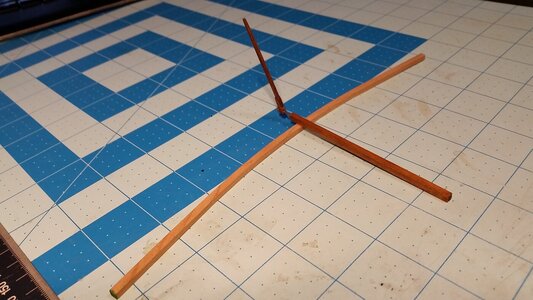
Parts shown with whipstaff near rudder midships position.
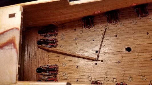
The location of the whipstaff hole was found and a hole drilled through the deck. The rowle and other details will be added after the hole is filed to the appropriate shape and size. Later, the arched piece serving as the quadrant will be installed, the the tiller inserted and the whipstaff placed into it, and the endcap glued on. Later in the build, the rudder will be attached to the tiller when it is ready to be fitted.
The length of the tiller was estimated, and I believe I can get an arc for the tiller of about +/- 30-35 degrees for the rudder. A long stick of 3x3mm cherry wood was soaked in water and bent onto an arc. This will support the bottom of the tiller, and be installed through holes to be cut in the hull later. It will be about 3mm below the overhead beam, and the tiller will be able to swing on top of this arc and below the beam overhead with a small clearance.
The whip staff was fashion by a stick walnut with a paddle shape containing the hole glued to the end of the staff. A length of 18 gauge brass wire with and end cap made from wood will hold the whipstaff to the tiller, and the end of the whipstaff can slide on the the length of wire to account for the fore-aft movement of the end of the tiller due to the arc of its motion.
But first, here my Bengal kitty Leopold kicking back with me after a hard day's work.

The tiller hole is rectangular, and was filed wider on the inside to allow space for the tiller to swing.

Test fitting of a stick to see how high the overhead beams are, determine the tiller length and arc of travel.

Below is an excerpt showing the basic plan in making the tiller and whipstaff. The rowle and deck fittings will be made later. The arched beam will act as the quadrant, but the tiller will ride above it, not below. This simplification was made because of the late installation and lack of access at this stage in the build.

Top view of the parts. The rudder will be at the bottom. The whipstaff is close to where it would be with full left rudder. Because of the height of the whipstaff, the steering compartment will have to extend upward into the upper gun deck.

Parts shown with whipstaff near rudder midships position.

The location of the whipstaff hole was found and a hole drilled through the deck. The rowle and other details will be added after the hole is filed to the appropriate shape and size. Later, the arched piece serving as the quadrant will be installed, the the tiller inserted and the whipstaff placed into it, and the endcap glued on. Later in the build, the rudder will be attached to the tiller when it is ready to be fitted.

Did you say you have an engineering degree?Construction of the tiller, whipstaff, and the arched tiller support were made after taking measurements off the hull. The tiller hole was cut first in the transom. It is lower than depicted in the Lely painting, since that painting was incorrect with respect to the height of the rudder and tiller location. A stick of 3x3mm walnut wood was used to check the position of the hole. The forward end of the stick, which will be made into the tiller, rests on the bottom of the overhead deck beam. Since the stock is near horizontal, the hole's vertical position is correct. AS long as I'm going through the trouble of making the whipstaff, it may as well be made to function like a real one. Movement of the rudder with your fingers should allow one to see the free movement of the whipstaff's angle and it's extension while viewing through the last gun port on the middle gun deck.
The length of the tiller was estimated, and I believe I can get an arc for the tiller of about +/- 30-35 degrees for the rudder. A long stick of 3x3mm cherry wood was soaked in water and bent onto an arc. This will support the bottom of the tiller, and be installed through holes to be cut in the hull later. It will be about 3mm below the overhead beam, and the tiller will be able to swing on top of this arc and below the beam overhead with a small clearance.
The whip staff was fashion by a stick walnut with a paddle shape containing the hole glued to the end of the staff. A length of 18 gauge brass wire with and end cap made from wood will hold the whipstaff to the tiller, and the end of the whipstaff can slide on the the length of wire to account for the fore-aft movement of the end of the tiller due to the arc of its motion.
But first, here my Bengal kitty Leopold kicking back with me after a hard day's work.
View attachment 308037
The tiller hole is rectangular, and was filed wider on the inside to allow space for the tiller to swing.
View attachment 308031
Test fitting of a stick to see how high the overhead beams are, determine the tiller length and arc of travel.
View attachment 308032
Below is an excerpt showing the basic plan in making the tiller and whipstaff. The rowle and deck fittings will be made later. The arched beam will act as the quadrant, but the tiller will ride above it, not below. This simplification was made because of the late installation and lack of access at this stage in the build.
View attachment 308033
Top view of the parts. The rudder will be at the bottom. The whipstaff is close to where it would be with full left rudder. Because of the height of the whipstaff, the steering compartment will have to extend upward into the upper gun deck.
View attachment 308034
Parts shown with whipstaff near rudder midships position.
View attachment 308035
The location of the whipstaff hole was found and a hole drilled through the deck. The rowle and other details will be added after the hole is filed to the appropriate shape and size. Later, the arched piece serving as the quadrant will be installed, the the tiller inserted and the whipstaff placed into it, and the endcap glued on. Later in the build, the rudder will be attached to the tiller when it is ready to be fitted.
View attachment 308036
- Joined
- Aug 8, 2019
- Messages
- 5,582
- Points
- 738

Could be a dentist tooDid you say you have an engineering degree?
Too smart to be a dentist...Could be a dentist too


