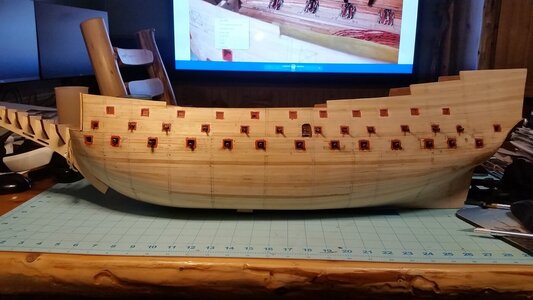
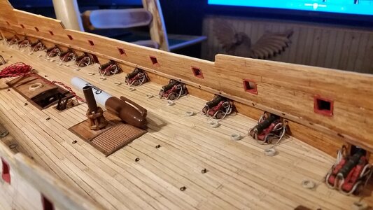
HMS Sovereign of the Seas - Bashing DeAgostini Beyond Believable Boundaries

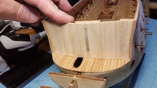
The beakhead bulkhead was made today, but it will not be not be permanently attached until the kit plywood bulkhead is completely removed. It was made in three layers of wood, so that when gun parts are cut, there will be no space between the inner and outer planking layers. Since the forecastle has a waisted profile when viewed from the front, with a slight flare at the top, a jig for making the beakhead bulkhead was made to create the double curve of the bulkhead using planks.

First, the overall shape of the curved bulkhead was established by the bottom piece of what will be a three-piece jig. This shape of this first piece was made using French curves and cut with a band saw. These pieces of made from balsa which will make cutting them away from the finished bulkhead later.
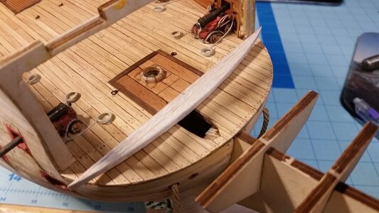
797 Begin Making Beakhead Bulkhead Jig.jpg

Knowing what the profile of the bulkhead allows the planks at the front edge of the foremast reinforcement to be trimmed by chisel cutting the line and removing the unwanted parts from the deck, all with a chisel bladed razor knife.
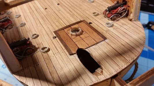
798 Trim Back Foremast Reinforcement Planking to Match Beakhead Bulkhead.jpg

You can see the edge of the foremast reinforcement flush with the front surface of the jig piece.
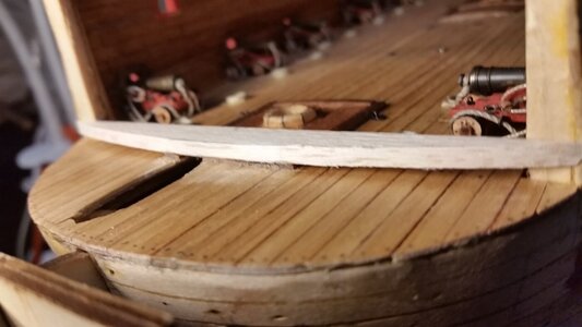
799 Test Fit Bottom Piece of Jig.jpg

The middle and top pieces of the jig are cut from balsa using a band saw. Note that the middle piece was cut and shaped to be at the level where the forecastle is the most narrow, so it is shorter than the ones above and below it.
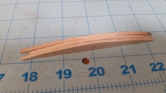
800 Top, Middle, and Bottom Parts of Jig.jpg

Sticks of spare linden wood are CA glued to the back of the three jig forms to create the jig.
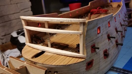
801 Assembling Bulkhead Jig.jpg

A few more sticks of linden wood are added to the jig to stiffen it.
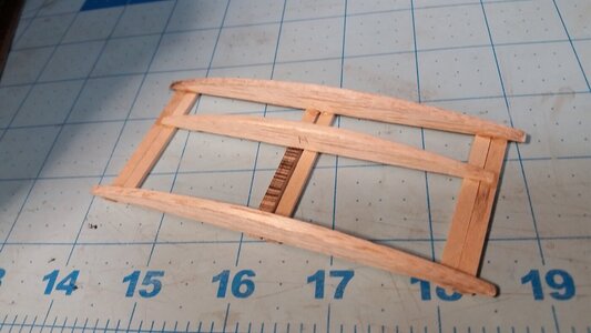
802 Reinforce Bulkhead Jig.jpg

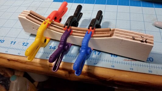
The bulkhead is now built as follows. Sticks of 4mm wide pliable basswood are glued edge-to-edge to each other in vertical planks, but only glued to the middle form of the jig, not at the top or bottom. The three outboard basswood planks on each side are soaked into water and pre-curved. This is so they do not have any spring in them as they are glued to each other and the middle form of the jig.
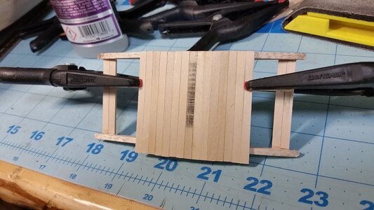
803 Glue Planks Edge to Edge and to Middle Jig Piece Only.jpg

Once all the planks are dry, the upper and lower forms of the jig are removed, but the center form is left glued to the planks to hold the shape of the bulkhead. The edges of the bulkhead are trimmed and sanded to fit the hull. Vertical trim made from thin mahogany sheet, are cut as glued to the outboard edges of the bulkhead. One these trim pieces is shown attached below.
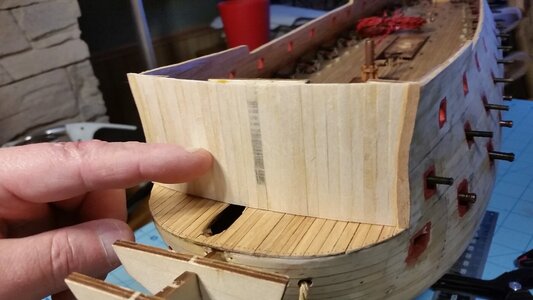
804 Cut Away Top and Bottom Pieces of Jig and Test Fit.jpg

Here the top view of the bulkhead held in place.
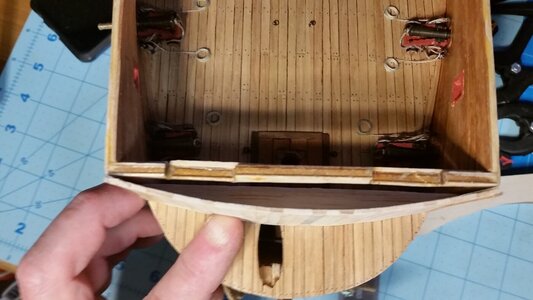
804 Top View of Beakhead Bulkhead.jpg

Here is the inside surface after sanding. You can see the waisted profile of the forecastle in the outboard edges. You can also see the middle jig form still in place.
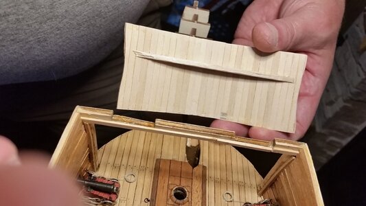
805 Sand Inside Surface and Shape Edges of Bulkhead to Fit Hull.jpg

Here is the front again.
806 Begin Planking Outside Surface.jpg

The final planking pattern is borrowed from John McKay's design.
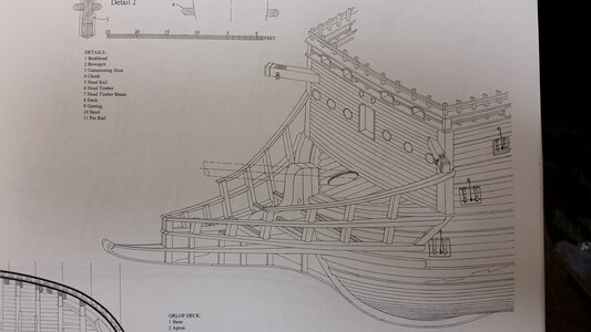
807 McKay Plan for Beakhead Bulkhead.jpg

Horizontal mahogany planks were glued to exterior side.
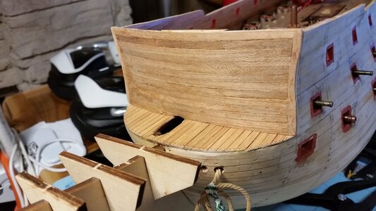
808 Exterior Planked.jpg

Planks of mahogany are beginning to be layered on the inside.
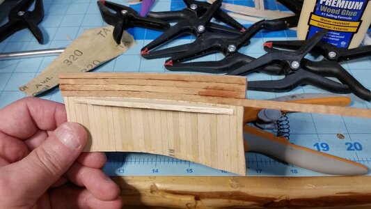
809 Begin Planking Interior.jpg

Now that the final exterior planking and some of the inside final planking is finished, the bulkhead is stiff enough to remove the middle jig form.
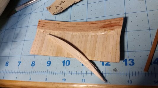
810 Remove Last Piece of Jig.jpg

The final planking on both sides is sanded and lacquered. However, it is not yet attached to the hull. Perfect fit!
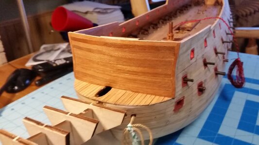
811 Bulkhead Sanded and Lacquered.jpg

Inside view. The cross support at the top of the forecastle and most of the the vertical plywood at the corner edges will be removed before the beakhead bulkhead is permanently attached, leaving a clean looking interior.
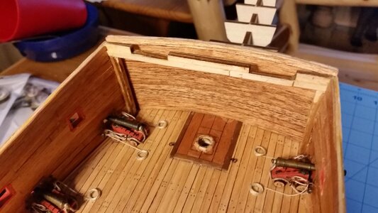
812 Bulkhead Test Fit.jpg
 
Beautiful custom work my friend!
The whole thing was really a geometry problem, mixing the large overall curve of the bulkhead with the subtle curve of the forecastle. The strips were made longer than the jig at the bottom to allow enough wood to trim the cambered shape of the deck at the bottom. The top is straight. Making a quick disposable profile jig lets you assemble the shape because the strips are individually pliable and is the same technique as planking a hull.
 
The remaining portions of the forecastle frame supports was removed, holes patched with planking on the deck, mahogany trim used to neaten the edges, and the beakhead bulkhead attached to the forecastle.

MOAR DESTRUCTION! A razor knife saw was used to carefully remove the remaining kit frame supports for the forecastle. The rough edges were sanded with a sanding stick.
813 Remove Remainder of Forecastle Frame Supports.jpg

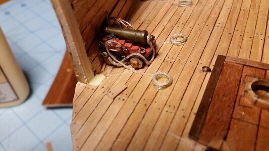
Holes in the deck planking exposed by removal of the supports are patched with tanganika planks make from scraps.
814 Patch Holes in Deck.jpg

Some mahogany was used to trim the rough and uneven edges of the bulwark planking.
815 Glue and Clamp Mahoganey Trim.jpg

Trim installed.
816 Mahogany Trim.jpg

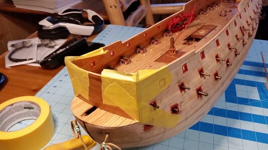
Beakhead bulkhead is glued to the forecastle.
817 Glue Beakhead Bulkhead to Forecastle.jpg
 
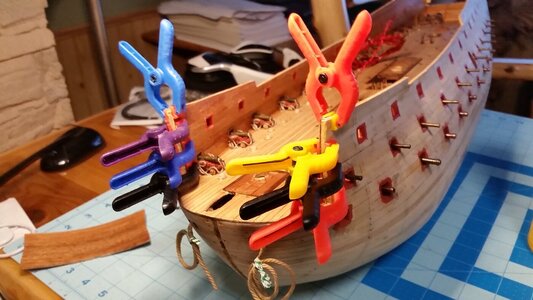
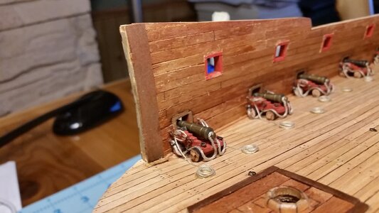
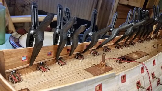
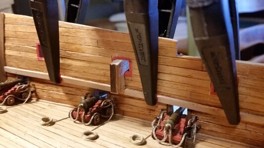
Preparation for making the upper gun deck support structure has begun. The gage used for determining the vertical position of the middle gun deck was used again, except that the top of the gage needed to be sanded down on the top edge a bit to fit the smaller gun ports of the upper gun deck. The gage is used to locate the deck support strips which are glued to the bulwarks. It is inserted into each gun port before a clamp is placed nearby and the CA glue on the strip allowed to harden. The vertical position of these strips is crucial in ensuring that the beams and eventually the deck are at the proper height. The system works pretty well, as evidenced by the result for the middle gun deck height.

View of the starboard deck support for the upper gun deck clamped to the bulwark.
818 Glue Deck Edge Support Strips.jpg

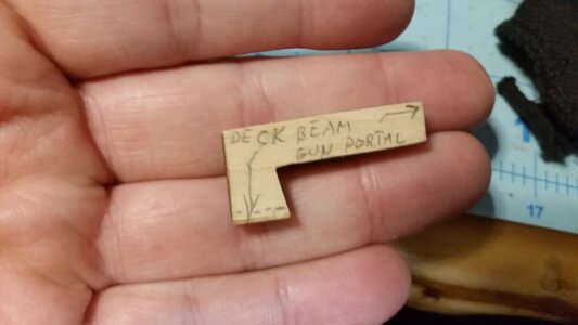
This is the deck height gage. The bottom of the gage is the level of the top surface of the deck beams and supports, and the dashed line is the top surface of the deck. The dimensions of the gage were carefully taken from the gun barrel centerline height above the deck, and thicknesses of the false deck and deck planking combined. The part that is inserted into the gun port fits those ports closely for consistency.
819 Deck Support Strip Gage.jpg

The gage is shown in place. The deck support strip is held against the bottom of the gage while placing the clamp nearby. THe gage is used in each gun port to ensure the deck height is correct for each gun.
829 Deck Support Gage in Gun Port.jpg

View of starboard deck support strip.
830 Stbd Deck Support Strip.jpg

View of port deck support strip.
831 Port Deck Support Strip.jpg

View of the beakhead bulkhead.
832 Beakhead Bulkhead.jpg

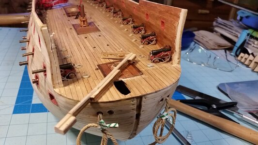
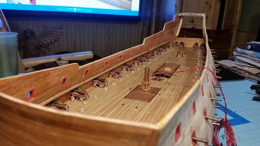
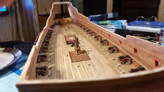
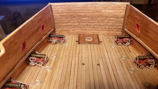
Progress so far...
833 Progress So Far.jpg
 
Preparation for making the upper gun deck support structure has begun. The gage used for determining the vertical position of the middle gun deck was used again, except that the top of the gage needed to be sanded down on the top edge a bit to fit the smaller gun ports of the upper gun deck. The gage is used to locate the deck support strips which are glued to the bulwarks. It is inserted into each gun port before a clamp is placed nearby and the CA glue on the strip allowed to harden. The vertical position of these strips is crucial in ensuring that the beams and eventually the deck are at the proper height. The system works pretty well, as evidenced by the result for the middle gun deck height.

View of the starboard deck support for the upper gun deck clamped to the bulwark.
View attachment 309011

This is the deck height gage. The bottom of the gage is the level of the top surface of the deck beams and supports, and the dashed line is the top surface of the deck. The dimensions of the gage were carefully taken from the gun barrel centerline height above the deck, and thicknesses of the false deck and deck planking combined. The part that is inserted into the gun port fits those ports closely for consistency.
View attachment 309012

The gage is shown in place. The deck support strip is held against the bottom of the gage while placing the clamp nearby. THe gage is used in each gun port to ensure the deck height is correct for each gun.
View attachment 309013

View of starboard deck support strip.
View attachment 309014

View of port deck support strip.
View attachment 309015

View of the beakhead bulkhead.
View attachment 309016

Progress so far...
View attachment 309017
Good morning Kurt. I’ve been away for a while and caught up this morning.That is some serious modeling and ingenious thinking superbly Executed....smurfs and all;). I am keenly interested to see how you plank with the extended barrels later on( I understand why you did it this way). So many great ideas come out of your log. Cheers Grant
 
let it longer in the form to dry and use a heatgun to harden. Then it keeps in shape. Did that to my anchors
I did apply some heat and they were dry when removed from the form. I can adjust the shape with my hands and flatten them a bit since they retain curvature for a long time. When you apply high heat, you soften the lignum in the wood and it goes plastic, allowing you to reshape it. Water also soften the wood. Steam is best, allowing for the most deformation without breaking. When you apply a hot iron to wet pieces of wood, you get instant steam and can curl wood really far.
 
This is one of those builds that makes a very enjoyable read Kurt. Some of your techniques, ideas and clever solutions are going to be very useful.
 
This is one of those builds that makes a very enjoyable read Kurt. Some of your techniques, ideas and clever solutions are going to be very useful.
Thanks Roger. This being only my second model, with much more complexity than the first, there are more opportunities for solving problems, learning to be a scratch builder. Glad some of the exploits have been instructional and not just entertaining. Despite all the detail in this build, it really is a balance between features I can add easily, and those (like carvings) which I cannot, and shortcuts need to be made by finding prefabricated parts or other methods, such as 3-D printing.
 
Back
Top