BS in Marine Engineering. It means I can BS my way through a ship model build.Did you say you have an engineering degree?
-

Win a Free Custom Engraved Brass Coin!!!
As a way to introduce our brass coins to the community, we will raffle off a free coin during the month of August. Follow link ABOVE for instructions for entering.
-

PRE-ORDER SHIPS IN SCALE TODAY!
The beloved Ships in Scale Magazine is back and charting a new course for 2026!
Discover new skills, new techniques, and new inspirations in every issue.
NOTE THAT OUR FIRST ISSUE WILL BE JAN/FEB 2026
You are using an out of date browser. It may not display this or other websites correctly.
You should upgrade or use an alternative browser.
You should upgrade or use an alternative browser.
HMS Sovereign of the Seas - Bashing DeAgostini Beyond Believable Boundaries
- Thread starter DARIVS ARCHITECTVS
- Start date
- Watchers 105
Says the guy who has a better looking hull and home made lines on his model . . .Too smart to be a dentist...
No way. Dentists scare me... like clowns and blimps do.Could be a dentist too

For some reason I find the fact that blimps scare you to be marvelously amusingNo way. Dentists scare me... like clowns and blimps do.
 . No wings? Sitting under a bag of explosive gases?
- Joined
- Aug 8, 2019
- Messages
- 5,584
- Points
- 738

Sometimes filled with bad breath.explosive gases
It takes a dentist to love that
Welcome to the DeAgostini club you will have fun. one of my german friends has it totally finished with a perfect result. DeAgostini is very popular in GermanyHMS Sovereign of the Seas - Bashing DeAgostini Beyond Believable Boundaries - by DARIVS ARCHITECTVS
Well, I just finished La Couronne and its display case a few hours ago, and swore that I would take a break before starting another project.
That didn't happen. On to Ship #2.
Research on building HMS Sovereign of the Seas started almost immediately. I opened Issues 1-15 of the kit and started pouring through their contents, eager to work on the one ship which is the greatest inspiration above all others. The first problem reared its ugly head immediately. The false keel assembly does not include the keel itself, ending at the garboard strake of planking. I could not use my multi-position keel vice that served my so well while building La Couronne! That meant that the base jig in the DeAgostini instructions has to be built and used. The keel is attached later in assembly, and I'm afraid that it won't be strong enough to use the keel vice, and one accidental bump on the hull will break the keel off, leaving the wrecked hull rolling on the floor. I guess I'll have to be careful.
Some more observations. This model has a complete lower gun deck, unlike Corel's La Couronne, so it will be easy to replace the false half-barrel cannons with complete carriages. (Don't look at me like that, Dockattner... You may take ALL the shortcuts you want! Not THIS sailor.) Because the kit instructions are scattered across 135 packages in magazines, the steps for assembling multiple similar items like cannons are also scattered, and there are no blueprints or rigging drawings to refer to that give you the complete picture of how elements like lines, decorations and other landmarks used in measuring are positioned, relative to each other and the hull overall. This is quite different than working from the two general arrangement drawings and seven rigging drawings that helps you classify and keep track of what you are working on, and where something goes.
Just to get something done, the first frame pieces of the bow were glued together, and some wood metal "L" brackets for making the base jig were purchased. There is still one more piece of wood to purchase before the base jig can be completed and the false keel assembled. Since I wanted to use those GORGEOUS Amati cast decorations on this model, the problem remains whether or not they would fit because the scales between the Amati and DeAgostini models are slightly different. Laying the false keel bulkheads on the Amati plans shows that they may actually be close enough to allow use of most of the Amati decorations. Each decoration, Amati or DeAgostini, will have to be chose based on how close to the Payne description of the decorations they are. Perhaps in some cases neither will work, and scratch built decorations will have to be made, which I do not have the patience, tools or talent to do. Carving is a slow, high risk task for me. Too much can go wrong. After all, I'm an engineer (Architectus in Latin), not an artist.
Many things will be replaced in this white metal casting, plywood ridden, arguably accurate DeAgostini kit. LET THE BASHING BEGIN.
View attachment 193270
It looks like somebody broke the sprit topmast, or it that just he camera lens effect?
View attachment 193271
This is NOT what the kit build would look like. This is the scratch built Italian made model that the simplified kit approximates, and falls short of:
View attachment 193277
View attachment 193272
View attachment 193273
The tiller and whipstaff were completed today.
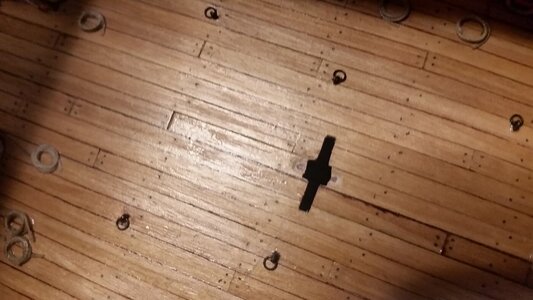
The slot for the tiller was cut, and and opening prepared to accept the rowle. Recesses fore and aft of the slot were created for the rowle shaft.
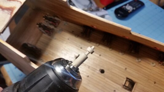
A piece of dowel was turned with a battery powered drill. A hobby saw cut slot down to the diameter of the shaft, and a square diamond file was used to shape the rowle wile it spun. A drill makes a good mini-lathe for tiny parts.
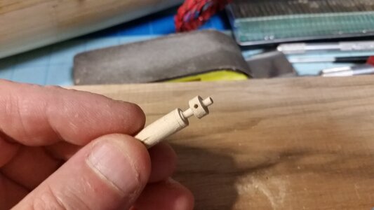
The pilot hole was drilled for the whipstaff. Larger drill bits were used in two more steps to bring the hole to the proper diameter.
Test fitting the whipstaff.
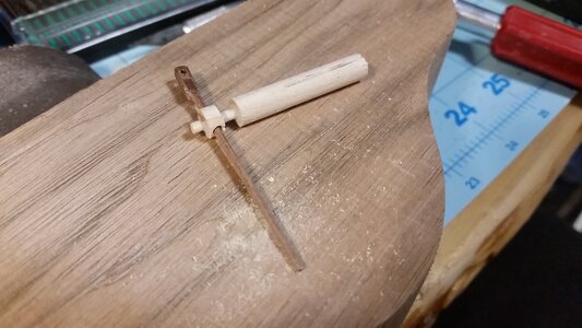
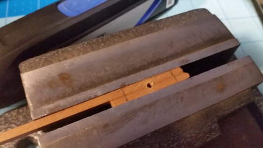
Two pieces of 3x3mm cherry wood were used to make the rowle partners, which holds the rowle in place. To make the semicircular cuts for the rowle shaft, both parts were placed opposite each other and one hole drilled, making the cuts even and quick. The pencil marks indicate where the parts will be cut to length.
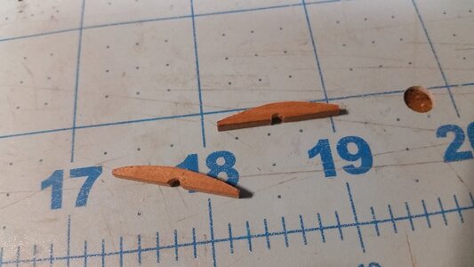
The rowle partners were cut and shaped to the proper camber.
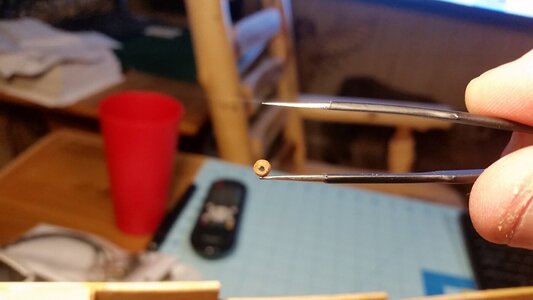
This button was made as the stopper that will be glued onto the end of the tiller tang to keep the whipstaff from falling off. In order to slip it onto the tang safely and not lose it in the hull, it is CA glued to one side of the tweezers.
The tiller is inserting into the stern.
The tiller is slipped onto the tang of the tiller and held in place with a clamp that is taped to the hull.
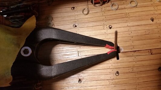
Here was the tricky part. Using the tweezers, the stop was inserted and carefully slipped onto the end of the brass tang. CA glue was applied from the end of a thin stick of wood to the end of the tang to cement it in place.
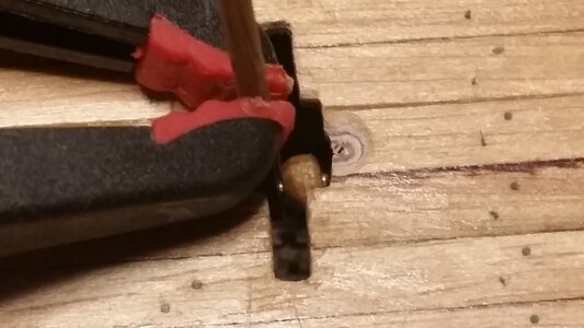
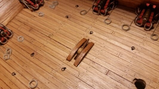
The rowl is slipped over the whipstaff with its shaft resting in the recesses in the deck. Now the rowle partners are glued to the deck with CA, being careful not get any CA glue on the rowle shaft. The rowle is now trapped in place and rotates freely, and the whipstaff can slide easily through its hole. The extreme angle of the tiller and whipstaff is carefully tested, without dropping the whipstaff all the way through the rowle.
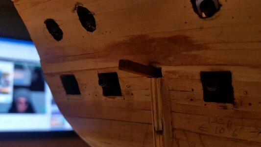
Now the tiller needs support from the bottom on its front end. After careful measurements, holes are drilled in the side of the hull. The quadrant is a curved beam that will support the tiller's front end across its entire arc of movement. The position of the holes was verified by sliding a 1.5x1.5mm stick of walnut through the hull using the holes, and the vertical play in the front end of the tiller was examined by moving the whipstaff up and down. The holes in the hull were enlarged to accept the arched quadrant beam, and needed to be adjusted downward as the holes were enlarged. The quadrant was slid into place. A flashlight was directed through the second hole and the end of the quadrant was maneuvered into the hole from the hull interior by looking through the open starboard stern gun port.
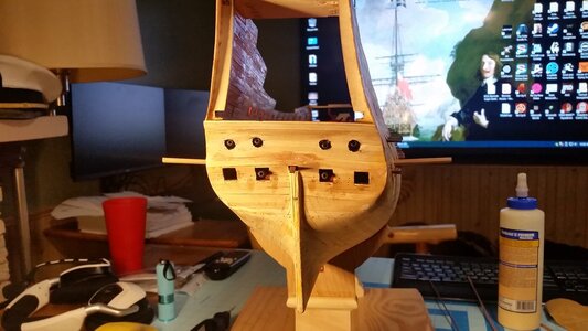
Here is the quadrant in position.
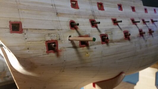
The quadrant was secured to the hull on both sides with PVA glue and wedged into place with a stick of walnut. The protruding wood will be cut away and made flush with the hull after the glue dries.
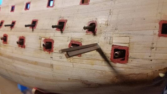
Test operating the whipstaff to extreme port and starboard positions. It works perfectly.
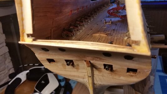
A couple small pieces of wood trim between the rowle partners, and the whipstaff is complete. The length of the whipstaff may be trimmed later. Currently it reaches to the overhead of the deck above. A slot in the deck above will be cut. On three deck ships, this was called the whipstaff passage. The whipstaff helmsman operates the whipstaff from the middle gun deck, even though it can be operated from the upper gun deck for the center portion of the arc of the tiller. Most of the heavy steering for ships of this period was done using the spritsail, sprit topsail, and lateen on the mizzen mast for these early ships, with the rudder only making slight course corrections when sailing a straight course.
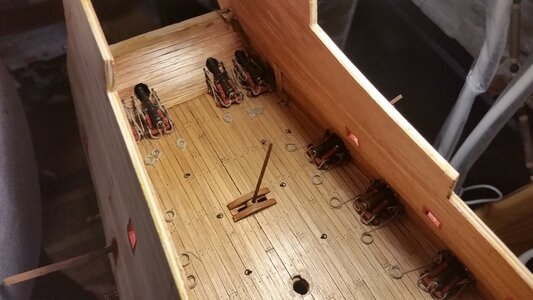
Why did I go through all this trouble to make a working steering mechanism no one will see or use? Because it was fun and I will able to take the display glass off the model and play with it. And cutaway ships look ugly to me because they resemble ship wrecks, and are incomplete. The question now is, have I forgotten anything else?
The slot for the tiller was cut, and and opening prepared to accept the rowle. Recesses fore and aft of the slot were created for the rowle shaft.

A piece of dowel was turned with a battery powered drill. A hobby saw cut slot down to the diameter of the shaft, and a square diamond file was used to shape the rowle wile it spun. A drill makes a good mini-lathe for tiny parts.

The pilot hole was drilled for the whipstaff. Larger drill bits were used in two more steps to bring the hole to the proper diameter.

Test fitting the whipstaff.

Two pieces of 3x3mm cherry wood were used to make the rowle partners, which holds the rowle in place. To make the semicircular cuts for the rowle shaft, both parts were placed opposite each other and one hole drilled, making the cuts even and quick. The pencil marks indicate where the parts will be cut to length.

The rowle partners were cut and shaped to the proper camber.

This button was made as the stopper that will be glued onto the end of the tiller tang to keep the whipstaff from falling off. In order to slip it onto the tang safely and not lose it in the hull, it is CA glued to one side of the tweezers.

The tiller is inserting into the stern.

The tiller is slipped onto the tang of the tiller and held in place with a clamp that is taped to the hull.

Here was the tricky part. Using the tweezers, the stop was inserted and carefully slipped onto the end of the brass tang. CA glue was applied from the end of a thin stick of wood to the end of the tang to cement it in place.

The rowl is slipped over the whipstaff with its shaft resting in the recesses in the deck. Now the rowle partners are glued to the deck with CA, being careful not get any CA glue on the rowle shaft. The rowle is now trapped in place and rotates freely, and the whipstaff can slide easily through its hole. The extreme angle of the tiller and whipstaff is carefully tested, without dropping the whipstaff all the way through the rowle.

Now the tiller needs support from the bottom on its front end. After careful measurements, holes are drilled in the side of the hull. The quadrant is a curved beam that will support the tiller's front end across its entire arc of movement. The position of the holes was verified by sliding a 1.5x1.5mm stick of walnut through the hull using the holes, and the vertical play in the front end of the tiller was examined by moving the whipstaff up and down. The holes in the hull were enlarged to accept the arched quadrant beam, and needed to be adjusted downward as the holes were enlarged. The quadrant was slid into place. A flashlight was directed through the second hole and the end of the quadrant was maneuvered into the hole from the hull interior by looking through the open starboard stern gun port.

Here is the quadrant in position.

The quadrant was secured to the hull on both sides with PVA glue and wedged into place with a stick of walnut. The protruding wood will be cut away and made flush with the hull after the glue dries.

Test operating the whipstaff to extreme port and starboard positions. It works perfectly.

A couple small pieces of wood trim between the rowle partners, and the whipstaff is complete. The length of the whipstaff may be trimmed later. Currently it reaches to the overhead of the deck above. A slot in the deck above will be cut. On three deck ships, this was called the whipstaff passage. The whipstaff helmsman operates the whipstaff from the middle gun deck, even though it can be operated from the upper gun deck for the center portion of the arc of the tiller. Most of the heavy steering for ships of this period was done using the spritsail, sprit topsail, and lateen on the mizzen mast for these early ships, with the rudder only making slight course corrections when sailing a straight course.

Why did I go through all this trouble to make a working steering mechanism no one will see or use? Because it was fun and I will able to take the display glass off the model and play with it. And cutaway ships look ugly to me because they resemble ship wrecks, and are incomplete. The question now is, have I forgotten anything else?
Last edited:
All I can say is it was fascinating and fun not to mention a great learning experience to watch how you achieved this installation.
Laparoscopic surgery on a ship. Amazing.
Where did you get the information on the use of whipstaffs? I just assumed it was done with ropes and pulleys. I suppose the Soleil Royal also uses a whipstaff instead of a wheel?
Laparoscopic surgery on a ship. Amazing.
 .. who else had to look that word up ?
- Joined
- Aug 8, 2019
- Messages
- 5,584
- Points
- 738

I'm not. Got experience with that in hospital... who else had to look that word up ?
- Joined
- Aug 30, 2020
- Messages
- 676
- Points
- 353

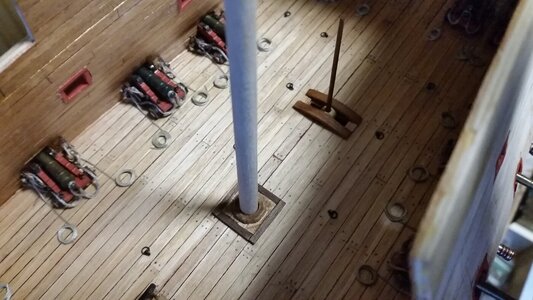
I do admire the work going into this build on all these extras, your canons have more work done on them and they will barley be be seen than my current builds canons that will be seen.Micro-update. Added the deck detail and wedges and coat for the mizzen mast. Wondering what to do next... maybe the beakhead bulkhead?
View attachment 308308
I imagine the satisfaction once this ship is completed will be huge knowing there has been plenty of effort in all the hidden details.
Ingenious retrofit Kurt.
I plan on the same feature on Soleil Royal.Yeah you can't use it but we know it is there.
Kind Regards
Nigel
I plan on the same feature on Soleil Royal.Yeah you can't use it but we know it is there.
Kind Regards
Nigel
The fun of moddeling is building it. When it is finished it is just a mantle piece.
So why won t we treat ourselves with building all these tiny details even if you don t see them. Because it is fun to make them. Great work Kurt love the whipstaff.
So why won t we treat ourselves with building all these tiny details even if you don t see them. Because it is fun to make them. Great work Kurt love the whipstaff.
I will see them. I have a borescope!I do admire the work going into this build on all these extras, your canons have more work done on them and they will barley be be seen than my current builds canons that will be seen.
I imagine the satisfaction once this ship is completed will be huge knowing there has been plenty of effort in all the hidden details.
See?
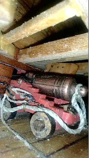
That’s awesome! Looks like you have one of the problems I have. These closeups show the tiniest specks of dust that I never see when looking at the ship with the naked eye.
Yes. Dust reflects bright light of the scope quite a bit. I would like to use ambient light, but the cameras in borescopes are not sensitive enough to create good images in very low light.That’s awesome! Looks like you have one of the problems I have. These closeups show the tiniest specks of dust that I never see when looking at the ship with the naked eye.


