HMS Sovereign of the Seas - Bashing DeAgostini Beyond Believable Boundaries

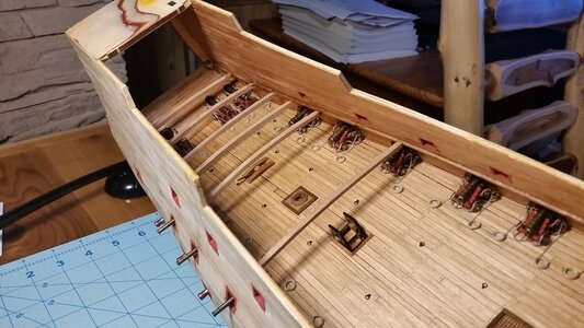
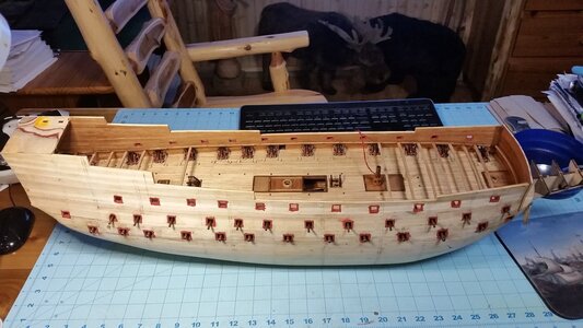
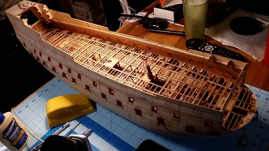
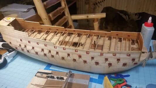
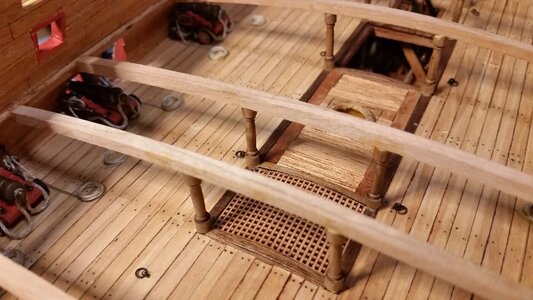
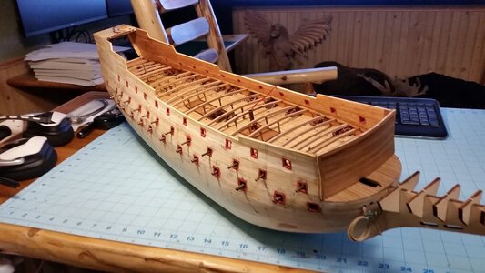
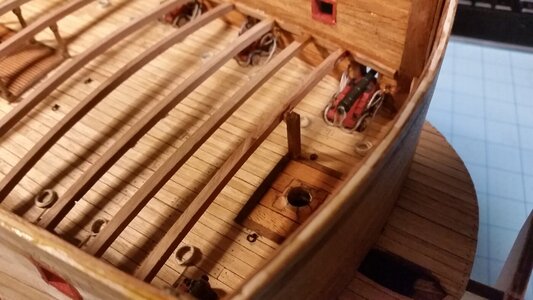
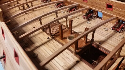
The beams were flattened out a bit by hand and trimmed to press-fit between the deck support strips. Several of the beams were fitted and glued in place. They were installed where they best fit with respect to length. The arc of each beam was adjusted such that the distance from the deck to the bottom of the beam is between 18mm and 22mm, with the greatest heights at the stern castle.

836 Begin Installing Upper Deck Beams.jpg

837 Begin Installing Upper Deck Beams.jpg

838 Progess So Far.jpg
 
Last edited:
Now this is fantastic. Will any given deck strake you glue down be able to touch each deck brace such that when you finish you have a reasonably smooth and uniformly cambered deck? By your description it seems if you laid a short piece across three beams, one of them could not be touching by as much as 4mm. From your photos they do look like they will all fit really well, the decking that is.
 
Now this is fantastic. Will any given deck strake you glue down be able to touch each deck brace such that when you finish you have a reasonably smooth and uniformly cambered deck? By your description it seems if you laid a short piece across three beams, one of them could not be touching by as much as 4mm. From your photos they do look like they will all fit really well, the decking that is.
The range of vertical height mentioned earlier results from a gradual sheer of the upper gun deck, which rises up at the stern castle about 4mm relative to the middle gun deck below it. This rise came about in the course of how the ship's hull shape and gun port layout turned out, not that it was planned.

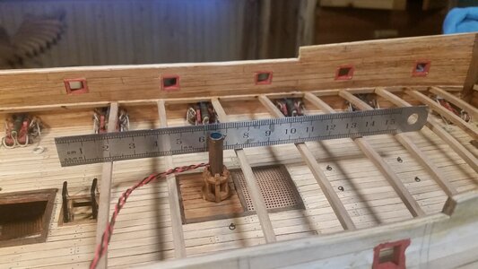
I usually get the camber and vertical location of the adjacent beams pretty close to each other, usually within 0.25mm. The beams have some flex, so higher ones can be pressed down a bit, evening out the deck. You can check beam height by placing your machined rule along the top of the beams. Minor variations won't matter much, because a 1mm layer of birch plywood is layered in patches over the top of the beams, and that's what ensures that the deck strips come out even, and at the proper camber. Minor gaps between the false deck and a beam won't matter. The beams are just the beginning. If you look at earlier posts in my build log, you'll see the whole process of building the deck structure for the lower gun deck. This is basically a repeat of that work.

The final result, prior to adding the false deck, will look like this:
1653059834768.png

Each deck will look like this. Please excuse the crappy photo. I used a cheap webcam.
1653060046981.png
 
Last edited:
The range of vertical height mentioned earlier results from a gradual sheer of the upper gun deck, which rises up at the stern castle about 4mm relative to the middle gun deck below it. This rise came about in the course of how the ship's hull shape and gun port layout turned out, not that it was planned.

I usually get the camber and vertical location of the adjacent beams pretty close to each other, usually within 0.25mm. The beams have some flex, so higher ones can be pressed down a bit, evening out the deck. You can check beam height by placing your machined rule along the top of the beams. Minor variations won't matter much, because a 1mm layer of birch plywood is layered in patches over the top of the beams, and that's what ensures that the deck strips come out even, and at the proper camber. Minor gaps between the false deck and a beam won't matter. The beams are just the beginning. If you look at earlier posts in my build log, you'll see the whole process of building the deck structure for the lower gun deck. This is basically a repeat of that work.

The final result, prior to adding the false deck, will look like this:
View attachment 309355
Ok I see from post 761. By the way the web cam shots make the lower deck look like a real ships' lower deck. Very impressive.
 
Ok I see from post 761. By the way the web cam shots make the lower deck look like a real ships' lower deck. Very impressive.
Yeah. I like the impression of a full scale ship the photos make. It is reminiscent of the photos of Wasa's lower decks, which were used to help develop the process for making the internal deck structures. The curvature of each beam and placement of the knees, ledges, and carlings is all done my eye. The process of making the deck structure is not as difficult as it looks, cutting small sticks and knees and fitting them one at a time. Keeping everything in proportion and keeping the entire structure even requires checking alignment of every piece along the way. Basic scratch building.
 
Last edited:
It just occurred to me that I almost missed a very important step as described by Charles Aldritch: "The rudder head and tiller are always just under the middle deck on a three decker". That means that the tiller of the rudder must be under the middle gun deck, near the overhead of the lower gun deck. I have not made an opening in the hull for the rudder tiller yet, since the hull exterior is not finished. However, since the lower gun deck is no longer accessible, now is the last chance to install the tiller by boring a hole in the transom, and installing the whipstaff on the middle gun deck. It also occurred to me that my reference to the space beneath the lower gun deck as the "orlop" deck was incorrect. On three deck ships before 1650, the lower gun deck IS CALLED THE ORLOP DECK, and the deck below that is nothing more than a series of platforms at slightly varying heights making up the hold, anchor cable storage spaces, and other spaces.

So... time to get clever again. The thing to do is bore the hole for the tiller in the stern, make a tiller, create a low steering platform on the middle gun deck, drill a hole in that for the whipstaff. The forward end tiller will have a rotating cylinder of sorts on the end with a hole in the side of it to accept the lower end of the whipstaff. With a flashlight, I will have to insert the tiller, from the stern, and simultaneously insert the whipstaff from the top, and with a bit of glue on the end of the whipstaff, glue it to the rotating part on the tiller. Then comes the fun part. There is a transverse beam that the forward end of the tiller rides on for support. This beam should have been installed while the lower gun deck was exposed. OOPS. So, all I have to do is drill two holes in the hull at the correct height, and insert a stick of cherry or walnut through the hull, just beneath the tiller, but fat enough below the middle gun deck support structure above so that the tiller can move freely between them, and glued the ends of this beam to the hull. Trim off the excess beam sticking out of the hull on either side and make them flush, and let the finish layer of planking hide the whole thing. Easy as pie, right? You gotta love model building gymnastics.

The rudder, tiller and whipstaff will actually function if all goes according to plan. Glad I caught this oversight before it was too late, or there would be no whipstaff to steer the ship! McKay placed his tiller and whipstaff each one deck too high, which is not correct for this type of ship.

It certainly pays to stand back and review your work now and again so nothing is missed!
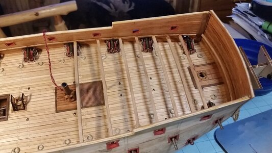
You are a brave, brave man, Kurt. Mel Gibson can't carry your water.
 
Added more beams today.

If the beams are within 1mm of each other in height, they will even out once you glued the false deck sections and place steel weights on top as the glue dries, because the beams all have some flex. When using a straight edge and a gap like the one at frames near 7.5, 10.5, and 13.5mm appears, understand that sheer in the deck could be the reason, not unevenness in the beams. This is the case below.
839 Checking Beam Position.jpg

All beams are in place except the ones that are where the mizzen mast and main mast are.
840 More Beams Added.jpg
 
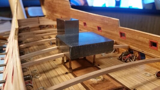
Today most of the columns were installed on the middle gun deck. More details will be added later before moving to the knees, ledges and carlings.

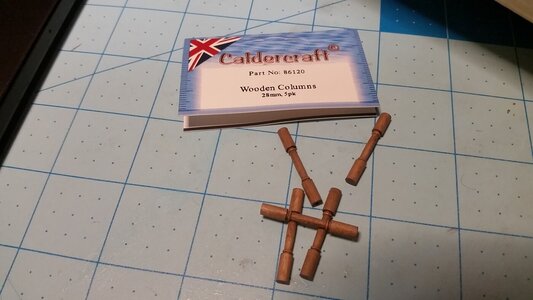
These wooden columns from Caldercraft are perfect for this model.
841 Caldercraft Columns.jpg

Sometimes the beams need to be pressed down with some weights. In most cases, the columns are an interference fit under the beams.
842 Cut and Install Columns.jpg

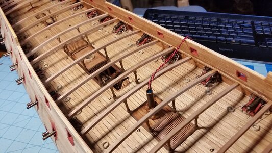
Most of the columns installed.
843 Columns Installed So Far.jpg

Close-up.
844 Columns.jpg

Progress so far.
845 Progress So Far.jpg
 
Today most of the columns were installed on the middle gun deck. More details will be added later before moving to the knees, ledges and carlings.

These wooden columns from Caldercraft are perfect for this model.
View attachment 310192

Sometimes the beams need to be pressed down with some weights. In most cases, the columns are an interference fit under the beams.
View attachment 310193

Most of the columns installed.
View attachment 310194

Close-up.
View attachment 310195

Progress so far.
View attachment 310196
Looks pretty nice for something that won't be seen by most casual observers, Kurt! Nice columns.
 
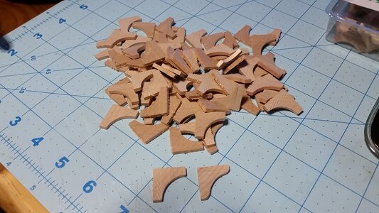
Adding more details. Added some columns which support the upper deck knight's heads near the main mast and foremast. A bunch of knees were cut from some corner molding, since it is close to the shape of the knees. These will be individually shaped, sanded and stained to become standard knees, handing knees, and lodging knees.

846 Install Column Support for Forward Knights Head.jpg

847 Install Column Supports for Main Knights Heads.jpg

Chopping all these parts off a length of molding took only 10 minutes with a bands saw. Sanding and shaping them will take much longer. Shaping the edge of each knee to the curve of the hull is done individually since the shape of the bulwark changes from stem to stern, but it goes fast with a sanding block and a couple test fits for each piece.
848 Cut Knees from Corner Molding.jpg
 
Last edited:
The amount of work is almost unthinkable. Amazing.
But it's easy work, Paul. It just takes time. Sanding and shaping all the knees with a sanding block is mindless work, best done while watching favorite re-run movies or listening to your favorite music, all this without a thought as to when the entire ship will be finished.
 
Last edited:
But it's easy work, Paul. It just takes time. Sanding and shaping all the knees with a sanding block is mindless work, best done while watching favorite re-run movies of listening to your favorite music, all this without a thought as to when the entire ship will be finished.
That may be true - but the time factor is a barrier to many. The magic happens when you truly don't care how long a build takes. I think I learned that from you.
 
That may be true - but the time factor is a barrier to many. The magic happens when you truly don't care how long a build takes. I think I learned that from you.
Definitely a good approach and attitude. I think the problem is that some people loose interest if they don't see instant results. I always put on my favorite music and just enjoy working on the model. If you loose track of time, then you are enjoying it. :)
At the end of the day, you have to put in the time regardless, so you might as well accept it...or find a new hobby! :p
You said it Dan! It's supposed to be fun.
 
Back
Top