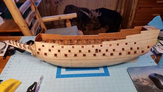
HMS Sovereign of the Seas - Bashing DeAgostini Beyond Believable Boundaries

Agree with all the above, all about the journey not arriving at the destinationThumbsupMusic is good for the repetive jobs.Depeche Mode for me for a while after learning of the passing of Andy Fletcher,their keyboard player yesterday:(

Kind Regards

Nigel
Joe Satriani is my first choice, all instrumental. Second choice is classical. ;)
 
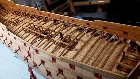
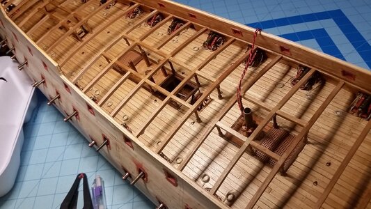
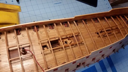
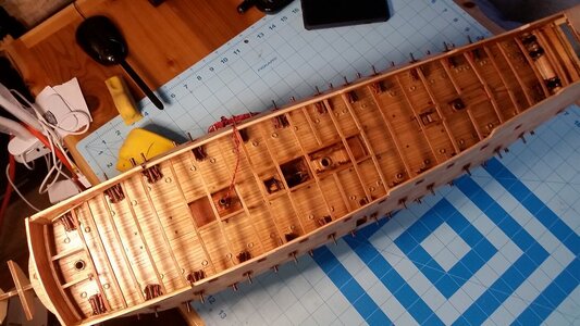
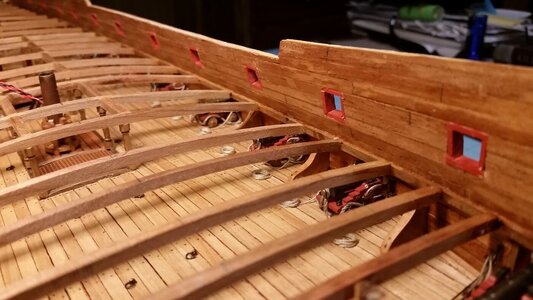
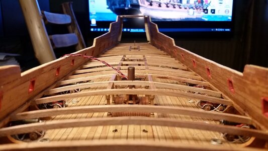
The longitunal beams that reinforce the upper deck openings were added today. Then, using John McKay's diagram for the deck support structure, which is as good as any guess as to the pattern of the supports, the lines were plotted for the centerline of all the carlings was drawn on the beams, first on the starboard side, then translated to the port side using the centerline markings and a drafting compass.
1653811988675.png

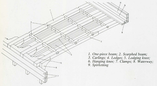
Basic deck support structure parts.
1653812616910.png

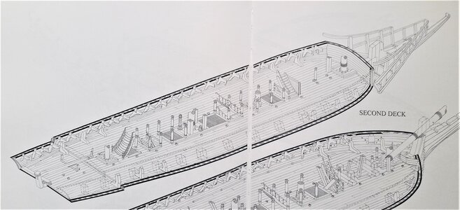
John McKay's plans for the upper deck, used as a basis for most of the features on this deck. Many features in his plans are correct, many are not. You have to verify everything from other sources, which make research harder, and choosing what to do is pure guesswork if no other sources describe a particular feature. Ladder arrangements were changed, and the rudder tiller was placed just below this deck and whipstaff is operable from this deck.
854 Upper Deck Plan from John McKay.jpg

855 Upper Deck Isometric Plan from John McKay.jpg

Looking to port and aft.
849 Added Longitudinals to Frame Hatches and Mast OPening.jpg

looking to starboard.
850 Port Side View.jpg

Top view.
851 Top View.jpg

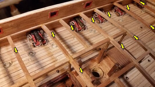
Pencil marks at centerline and at the center of where the carlings will be installed between the beams.
852 Mark Centerline of Ship and Where Carlings will go.jpg

Progress so far. Standard and hanging knees are next.
853 Progress So Far.jpg
 
Last edited:
Your great work continues to be very impressive Kurt.
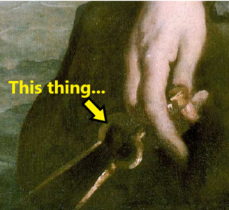
By the way, I think your photo of “this thing” shows a brass chart dividers. The curved top sections make it easy to close and open the dividers - a bit of hand dexterity required though :).
 
The longitunal beams that reinforce the upper deck openings were added today. Then, using John McKay's diagram for the deck support structure, which is as good as any guess as to the pattern of the supports, the lines were plotted for the centerline of all the carlings was drawn on the beams, first on the starboard side, then translated to the port side using the centerline markings and a drafting compass.
View attachment 311184

Basic deck support structure parts.
View attachment 311203

Looking to port and aft.
View attachment 311185

looking to starboard.
View attachment 311186

Top view.
View attachment 311187

Pencil marks at centerline and at the center of where the carlings will be installed between the beams.
View attachment 311188

Progress so far. Standard and hanging knees are next.
View attachment 311189
Beautiful work! Stunning actually!
 
Seems that The Learner's first stop on the forum was your build. I would have decided at that very moment in time to try a different hobby ROTF ROTF ROTF.
No kidding! ROTF
He would have been equally dismayed at your micro painted castings! I certainly am.
And now he’s reading the posts from you two and panicking :D.
 
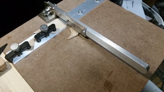
All twelve standard knees which support the middle gun deck were fabricated and installed. The 2.5mm thick slices of pine corner molding cut earlier are individually cut and fit. The main tools used are the chopping tool for rough shaping and the coarse sanding block, used for shaping the knees.

The chopping tool is used to make the first cuts, estimating the angle between the deck and the bulwark, which changes as you move from fore to aft. A tweezers is used to hold the part for test fitting, and the angle of the knee is adjusted as necessary.
856 Estimate Deck to Bulwark Angle and Cut.jpg

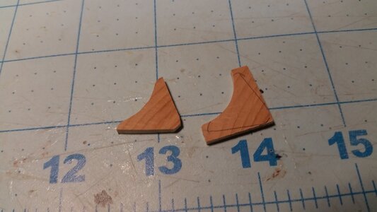
Once a knee is fitted on side, trace its outline on another piece and cut it out, and it will be a great fit, or very close, for the knee on the opposite side of the ship.
857 Shape On Knee then Copy for Other Side.jpg

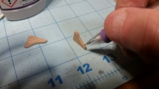
Mark the bolt heads with a 0.5mm mechanical pencil. At this scale, simply drawing details can add a lotto the model with minimal effort.
858 Draw Boltheads with Pencil.jpg

Apply CA glue and install the knee. Clean up any excess CA by dabbing the area with a Q-tip cotton swab.
859 CA Glue to Model.jpg

One of the knees glued in position. The boltheads had to be marked on this one after it was installed.
860 Standard Knee Installed.jpg

Standard knees on the starboard side forward. All of the knees are coated with Krylon Satin Finish using a brush. It darkens them a bit, brings out the color, and blends in dark spots created by the CA glue, making them invisible.
862 Stbd Forward Standard Knees.jpg

Standard knees on the starboard side aft.
863 Stbd Aft Standard Knees.jpg

Standard knees on the port side forward.
864 Stbd Aft Standard Knees.jpg

Progress of the upper deck structure so far.
865 Upper Deck Structure So Far.jpg

861 Standard Knee.jpg
 
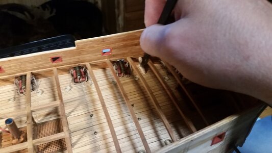
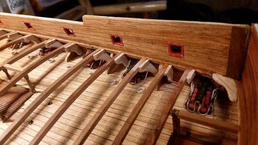
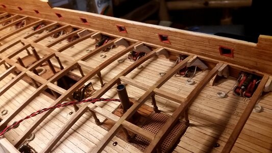
Lots of work fitting and installing hanging and dagger knees was done on the port side today. There were several gun ports close to beams which required dagger knees.

The pinewood corner molding pieces cut earlier were sanded on both sides. One knee was cut and shaped to fit a location near the midships. this will form a pattern for most of the others, which vary slightly because of changes in the angle of bulwark and a slight increase in deck height as you go aft.
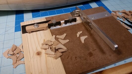
866 Cut Out Knees with Chopper.jpg

The basic outline of each knee is cut out with the chopper and then it is sanded to shape. A pencil is used to simulate the bolt heads.
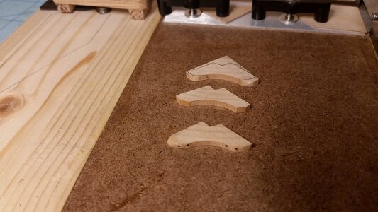
867 Cut and Sand to Shape.jpg

The knee is test fit before being glued with PVA glue. I used to use CA glue for this, because it was faster, but one of the knees popped loose on the deck below because of the glues brittleness. PVA is much more flexible but takes longer to dry. Well fitted parts make for a better and faster bond. Excess glue is scraped away with end of a wooden stick before it dries. This is not precise work as far as the joints go, but when photographed after it is done, the impression is still realistic enough.
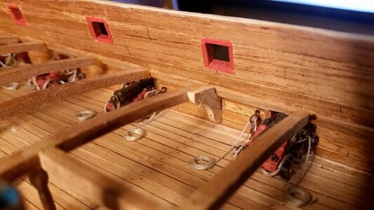
868 Fit Knees to Beam and Bulwark.jpg

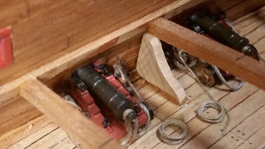
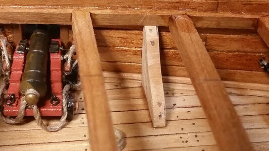
Where beams are close to or over gun ports, the carriages would interfere with hanging knees, so dagger knees are used instead. They are angles off to one side or the other to make room for the guns when required. The simple way to make them is by sanding the top edge to the desired angle, usually 45 degrees, and glue a second piece on top as shown.
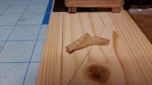
869 Make Dagger Knees to Avoid Gun Carriages.jpg

The ends are sanded to the proper shape and the knee is test fitted. After any needed sanding to make adjustments, it is glued in place.
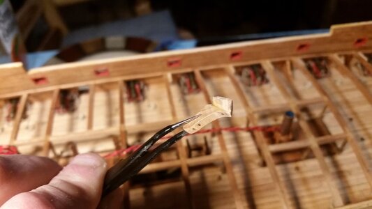
870 Completed Dagger Knee.jpg

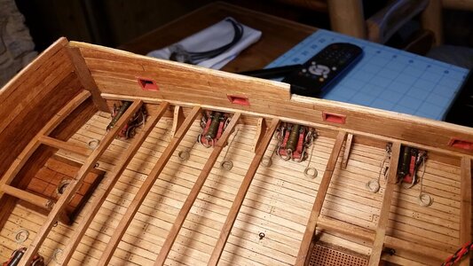
The port bow area has all the hanging knees installed, and three dagger knees can be seen. A knee braces the forward bulkhead to the bulwark as well.
871 Begin Lodging and Dagger Knees on.jpg

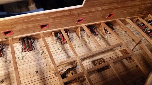
Farther aft, more knees were installed. This is all the farther I got today. The top edges of the knees don't have to be perfectly even with the top surface of the beams because a thin false deck will be laid over this and any gaps will not be visible. When all knees are done, they will be coated with satin finish to blend them in.
872 More Lodging and Dagger Knees.jpg

Progress so far.
873 Progess So Far.jpg
 
Back
Top