HMS Sovereign of the Seas - Bashing DeAgostini Beyond Believable Boundaries

Kurt,

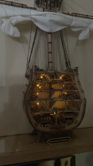
YES! I wish that I read about your Evans LED's before installing mine in the Santisima. I did NOT solder the connections (just twists everywhere) - now a couple of lights, flicker or don't stay lit.
I will need to open the case and revisit the connections that are at the back and run under the base to an on/off button. yikes!! - this was taken when all was OK


IMG_1564.jpeg
 
Kurt,

YES! I wish that I read about your Evans LED's before installing mine in the Santisima. I did NOT solder the connections (just twists everywhere) - now a couple of lights, flicker or don't stay lit.
I will need to open the case and revisit the connections that are at the back and run under the base to an on/off button. yikes!! - this was taken when all was OK


View attachment 316924
Soldering your connections is definitely the way to go and even then...
Check, recheck and check again your connections whenever you do something, anything in the vicinity of any light-related connection. Especially the connections to the lights themselves are rather finicky.
At one point I considered doing what you did; I'm glad I didn't follow through on that idea, based on your experience.
 
Kurt,

YES! I wish that I read about your Evans LED's before installing mine in the Santisima. I did NOT solder the connections (just twists everywhere) - now a couple of lights, flicker or don't stay lit.
I will need to open the case and revisit the connections that are at the back and run under the base to an on/off button. yikes!! - this was taken when all was OK


View attachment 316924
The problem with twist copper wire connections is that corrosion will eventually cause spots in you circuits to open, maybe not for a long time, depending on luck.
 
Last edited:
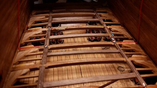
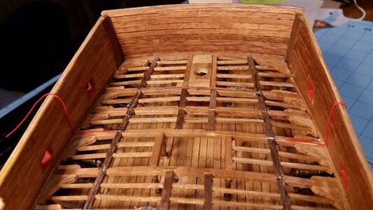
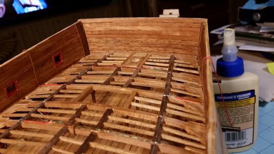
Finally, after thinking about the next step, wiring was routed for the stern castle and forecastle, and the false deck was started. I had one circuit of wiring for LED lighting reserved in the form of a coil of wire left. Instead of routing that wiring fore and aft, wires will be run upward from the positive and negative conduits already installed on the deck at each end of the ship. The unused wiring in the capstan shaft was just cut off and the ends sealed with glue to prevent shorting. The four wires running up for the quarterdeck and forecastle upper deck were painted brown to help hide them. Cannons and hanging knees will also obscure them later from being seen easily. So, only two live circuits will light this model, the one for the lower gun deck and the one for all the decks, galleries, and stern lanterns above that.

The process of fitting false deck sections from 3-ply, 0.58mm birch plywood (available at Menards stores in the USA) is described below. A few sections were installed today.

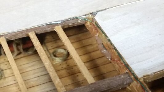
Two red wires were soldered to the conduits that power the middle gun deck LED's. These are run upward for later use. They are held to the beam with PVA, which is now invisible because it has dried. The stern of the ship is shown below.
963 Run Lighting Power Wires up in Stern.jpg

Another set of wires are connected by solder to the conduits under the forecastle and routed upward.
964 Run Lighting Power Wires up for Forecastle.jpg

The wires are painted brown.
965 Painted Wires Brown.jpg

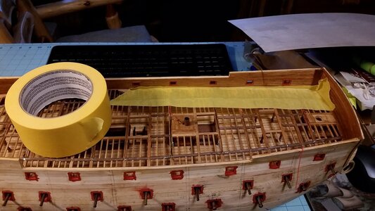
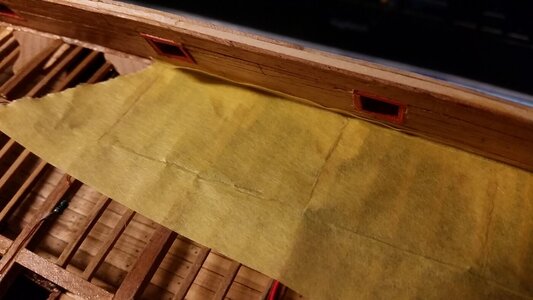
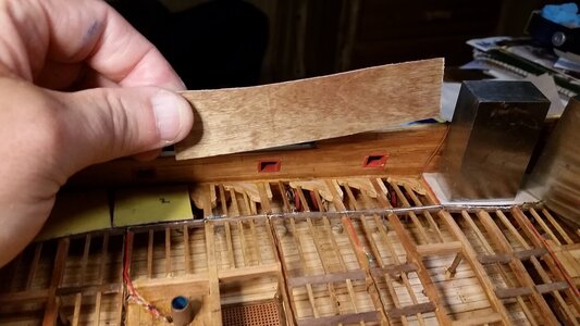
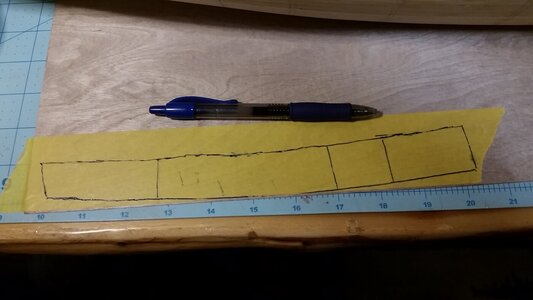
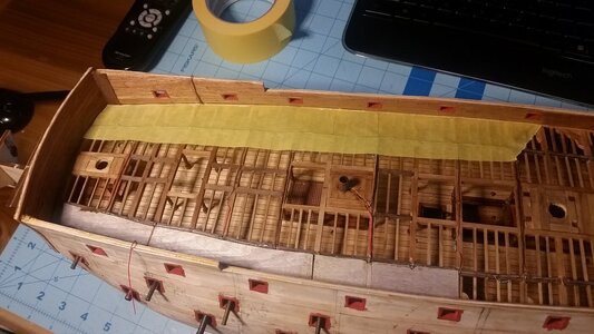
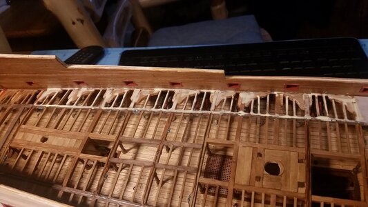
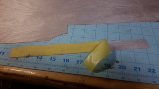
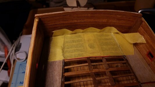
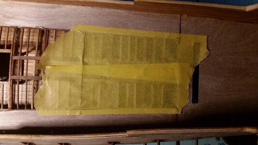
The "tape pull" method is used to make patterns for the deck pieces. A strip of masking tape is laid onto the structure for the deck pieces running along the bulwark. The time to remember if there are any missing attachments or features to be added to the middle gun deck is now, because soon it will be inaccessible.
966 Apply Tape to Make Deck Pattern.jpg

A pencil is used to mark the edges of the pieces. The pieces fit between the wires, so the wires will lay in the gaps between the pieces.
967 Mark Pencil Lines where Wires Are.jpg

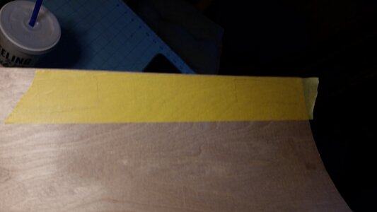
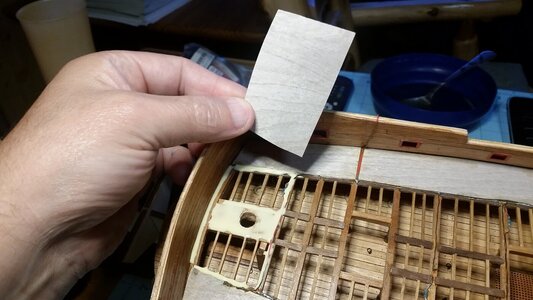
The tape is carefully pulled from the model and laid out onto the thin plywood.
968 Pull Tape and Place onto Thin Plywood.jpg

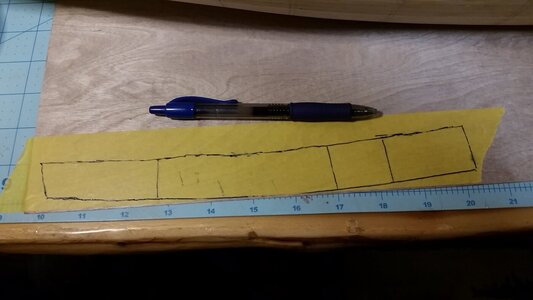
The pencil lines are drawn over with pen to darken them.
969 Darken Lines with Pen.jpg

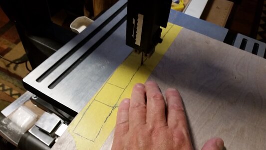
The pieces are cut using a bandsaw.
970 Cut Deck Pieces with Bandsaw.jpg

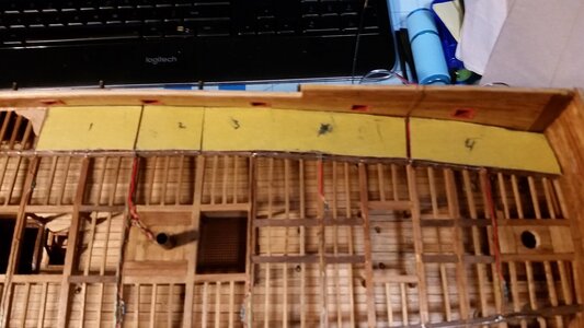
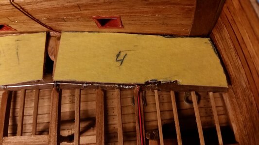
The pieces are numbered to keep them organized. The edges are cut a bit shorter so the pieces lay between the wires, with the seams over beams and carlings, leaving no visible gaps in the deck as viewed from the bottom. The pieces are trimmed to fit.
971 Test Fit False Deck Pieces.jpg

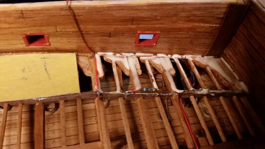
Edges are trimmed as necessary for wires and resistors so the deck piece lays as flat as possible.
972 Trim Edges to Avoid Wiring and Resistors.jpg

PVA glue is applied to the deck structure with a paint brush.
973 Apply PVA Glue.jpg

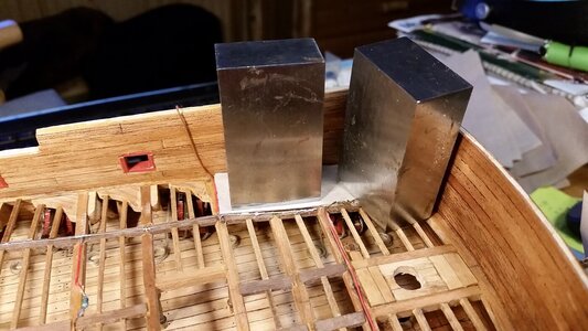
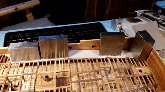
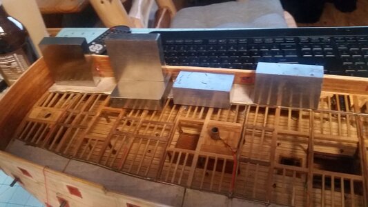
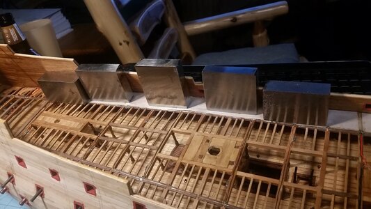
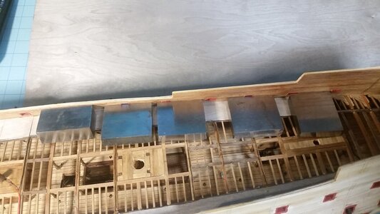
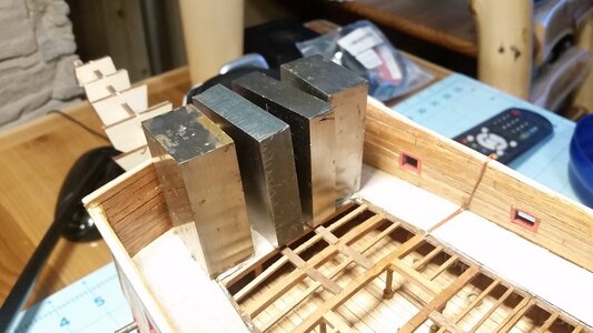
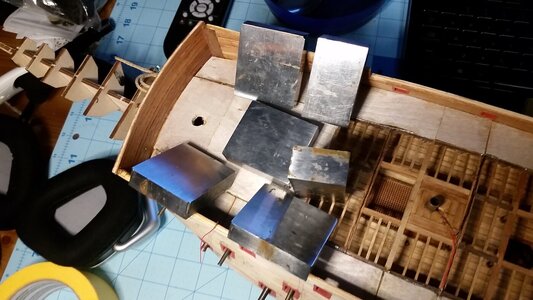
The piece is laid in place and held with weights until dry.
974 Glue Deck Piece in Place and Hold With Weights.jpg

The next piece is installed the same as the first. Note that the stained side of the plywood faced down. Staining was done earlier using Light Walnut Danish Oil.
975 Glue Next Deck Piece Down.jpg

All the pieces are allowed to dry for about 25 minutes.
976 Use Weights to Hold Deck Pieces Until Dry.jpg

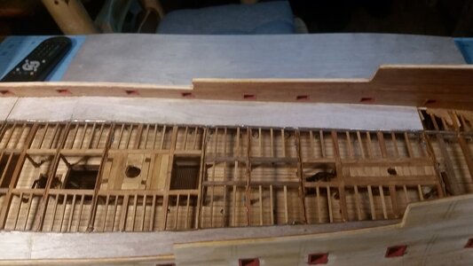
Despite a couple low spots in the deck due to variation in height of the beams, the deck is very close to level. Using multiple pieces to form the false deck makes forming the camber and shear curvature of the deck is much easier than trying to force large pieces to conform to the curves. More false deck pieces to follow.
977 Deck Pieces Installed so far.jpg

965 Painted Wires Brown.jpg

969 Darken Lines with Pen.jpg
 
Last edited:
Finally, after thinking about the next step, wiring was routed for the stern castle and forecastle, and the false deck was started. I had one circuit of wiring for LED lighting reserved in the form of a coil of wire left. Instead of routing that wiring fore and aft, wires will be run upward from the positive and negative conduits already installed on the deck at each end of the ship. The unused wiring in the capstan shaft was just cut off and the ends sealed with glue to prevent shorting. The four wires running up for the quarterdeck and forecastle upper deck were painted brown to help hide them. Cannons and hanging knees will also obscure them later from being seen easily. So, only two live circuits will light this model, the one for the lower gun deck and the one for all the decks, galleries, and stern lanterns above that.

The process of fitting false deck sections from 3-ply, 0.58mm birch plywood (available at Menards stores in the USA) is described below. A few sections were installed today.

Two red wires were soldered to the conduits that power the middle gun deck LED's. These are run upward for later use. They are held to the beam with PVA, which is now invisible because it has dried. The stern of the ship is shown below.
View attachment 317205

Another set of wires are connected by solder to the conduits under the forecastle and routed upward.
View attachment 317206

The wires are painted brown.
View attachment 317220

The "tape pull" method is used to make patterns for the deck pieces. A strip of masking tape is laid onto the structure for the deck pieces running along the bulwark. The time to remember if there are any missing attachments or features to be added to the middle gun deck is now, because soon it will be inaccessible.
View attachment 317208

A pencil is used to mark the edges of the pieces. The pieces fit between the wires, so the wires will lay in the gaps between the pieces.
View attachment 317209

The tape is carefully pulled from the model and laid out onto the thin plywood.
View attachment 317210

The pencil lines are drawn over with pen to darken them.
View attachment 317221

The pieces are cut using a bandsaw.
View attachment 317212

The pieces are numbered to keep them organized. The edges are cut a bit shorter so the pieces lay between the wires, with the seams over beams and carlings, leaving no visible gaps in the deck as viewed from the bottom. The pieces are trimmed to fit.
View attachment 317213

Edges are trimmed as necessary for wires and resistors so the deck piece lays as flat as possible.
View attachment 317214

PVA glue is applied to the deck structure with a paint brush.
View attachment 317215

The piece is laid in place and held with weights until dry.
View attachment 317216

The next piece is installed the same as the first. Note that the stained side of the plywood faced down. Staining was done earlier using Light Walnut Danish Oil.
View attachment 317217

All the pieces are allowed to dry for about 25 minutes.
View attachment 317218

Despite a couple low spots in the deck due to variation in height of the beams, the deck is very close to level. Using multiple pieces to form the false deck makes forming the camber and shear curvature of the deck is much easier than trying to force large pieces to conform to the curves. More false deck pieces to follow.
View attachment 317219

View attachment 317207

View attachment 317211
Good Morning Kurt- in depth and impressive. Watching you build is like an instruction manual for 18th Century ship building. Cheers Grant
 
Your love of all things nautical, your knowledge of engineering, and your skills at working with small things are inspiring, Kurt.
Thanks to you and Heinrich and GrantTyler. Really glad you guys like this model. For me it's been an inspiration realized. As you can tell from the timing of build log, it takes longer to contemplate each step that actually doing it, because the contemplation is necessary to prevent screwups and forgotten features. I still want to learn how to be as neat and tidy as Paul Kattner and Ohla Batchvarov. That will come in time with patience. This model is a series of tiny projects, each its own model. That's why the detail level is higher than average, in places normally unadorned.
 
A couple more deck pieces were installed today.

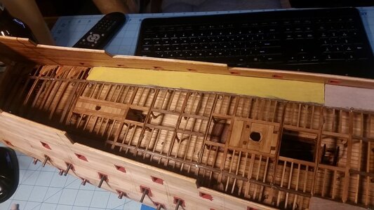
Masking tape applied to the support structure with pencil lines used to mark the edges of the next deck piece on the starboard side.
978 Masking Tape for Next Tape Pull  Pattern.jpg

Masking tape pull off the model and laid onto thin plywood, then cut along the lines using a bandsaw. The piece was glued in place, and is held with weights until drying.
979 Glue Stbd Plywood False Deck Pieces.jpg

A deck piece on the portside was made using another tape-pull pattern. Here it is test fitted.
980 Test Fit Deck Piece on Port Side.jpg

Apply PVA glue.
981 Apply PVA Glue.jpg
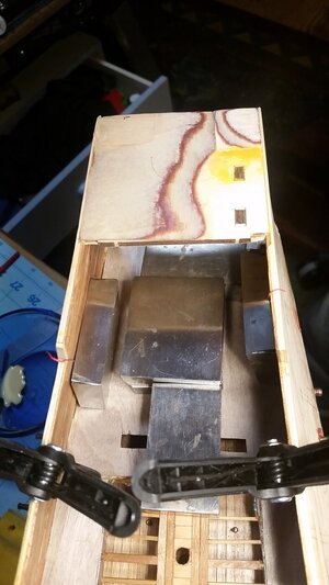
Deck piece in place and held by steel weights.
982 Glue and Weight Deck Piece Down.jpg

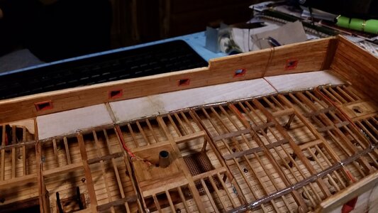
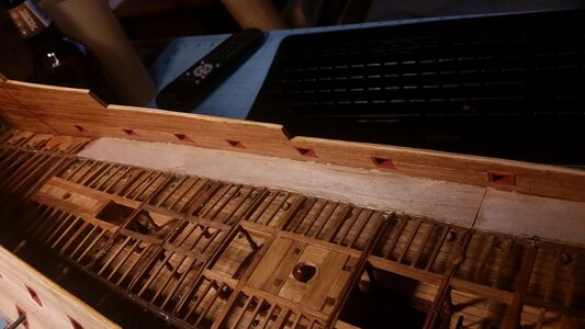
Finished piece.
983 Deck Piece Installed.jpg

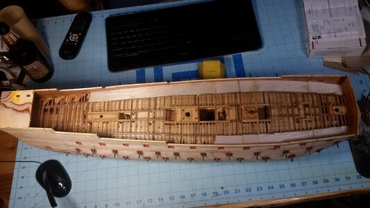
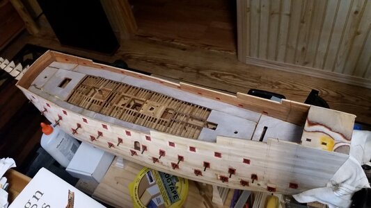
Progress so far. This wood is so thin that you don't really have to use a bandsaw, but it's a little faster for long pieces than using the scissors.
984 Progress So Far.jpg
 
A couple more deck pieces were installed today.

Masking tape applied to the support structure with pencil lines used to mark the edges of the next deck piece on the starboard side.
View attachment 317578

Masking tape pull off the model and laid onto thin plywood, then cut along the lines using a bandsaw. The piece was glued in place, and is held with weights until drying.
View attachment 317579

A deck piece on the portside was made using another tape-pull pattern. Here it is test fitted.
View attachment 317580

Apply PVA glue.
View attachment 317581

Deck piece in place and held by steel weights.
View attachment 317582

Finished piece.
View attachment 317583

Progress so far. This wood is so thin that you don't really have to use a bandsaw, but it's a little faster for long pieces than using the scissors.
View attachment 317584
Would veneer work as well? Or is it much thicker?
 
Would veneer work as well? Or is it much thicker?
Veneer is thinner, and prone to cracking along the grain, but as an underlayment to the deck planking, it would work. The beechwood plywood is made out of three very thin layers of veneer in perpendicular grain directions, and very strong, but only 0.48mm thick and it won't crack even with lots of force applied.
 
Veneer is thinner, and prone to cracking along the grain, but as an underlayment to the deck planking, it would work. The beechwood plywood is made out of three very thin layers of veneer in perpendicular grain directions, and very strong, but only 0.48mm thick and it won't crack even with lots of force applied.
Ach, so!
 
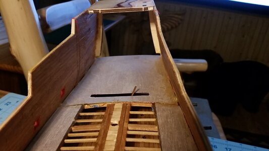
This is almost as boring as watching ratlines grow, but here we go. Another strip of deck was applied to the starboard side, then a large piece cut and installed in the stern. A slot had to be carefully measured and cut to allow for the whipstaff. A helmsman could operate the whipstaff more much of the rudder's swing angle, but men below this deck would be required to slide the whipstaff all the way in to position the rudder at extreme angles.

Removing tape from starboard side deck piece.
985 Stbd Side Deck Strip.jpg

Weights holding deck piece until glue dries.
986 Weights Holding Stbd Deck Piece.jpg

Deck piece installed.
987 Stbd Deck Piece Done.jpg

Test fit of stern deck piece.
988 Test Fit Stern Deck Piece.jpg

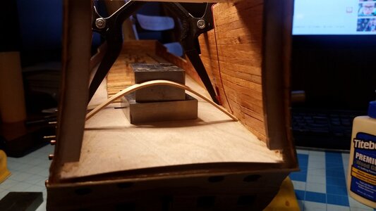
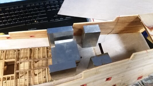
Weights holding stern deck section down.
989 Weights Holding Stern Deck Piece.jpg

A bamboo strip was used to hold the edges down until the glue dried. The weights we not able to reach the points where pressure was needed.
990 Bamboo Strip Holds Edges Down.jpg

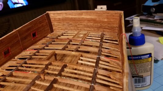
Stern deck section installed, with whipstaff visible.
991 Finished  Stern Deck Piece.jpg
 
Great approach to your deck Kurt. Do you have a link to your source of the plywood veneer? I have a need in the near future to create a false deck to support deck planking and for the life of me have not been able to find anything thin enough, while providing the required strenght. 0.48mm with 3 ply is exactly what I'm looking for.

Thanks,
Ken
I got the plywood at Menards HERE.
 
There is nothing boring about this. I find it fascinating to see how everything falls into place. Keep it coming!
 
Work continues. More false deck sections added to the upper gun deck (weather deck). So far, I have 1,001 photos in this build log. :DThumbsup

Making a tape pattern.
993 Make Tape Pattern for Fwd Deck Piece.jpg

Gluing deck piece.
994 Glue Fwd Deck Piece.jpg

Hold deck section down with weights until dry.
995 Hold Fwd Deck Piece with Weights.jpg

Finished forward deck section.
996 Drill and FIle Hole for Foremast.jpg

Another tape pull for the a center deck piece aft.
997 Make Tape Pattern for Center Aft Deck Piece.jpg

Piece glued in place with weights.
998 Glue and Hold Piece with Weights.jpg

Another forward center piece glued in place and held with weights. Let me know if this is boring you.
999 Center Fwd Deck Piece.jpg

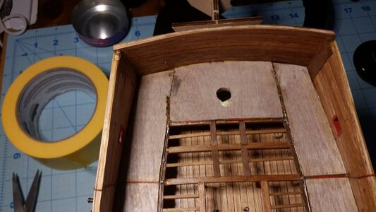
All exposed resistors for the lights were painted brown to help blend them in. They are are on the side of the beams and carlings because they won't fit under the deck.
1000 Paint All Exposed Resistors Brown.jpg

Progress so far. Seven more deck sections to go...
1001 Progress So Far.jpg
 
This is almost as boring as watching ratlines grow, but here we go. Another strip of deck was applied to the starboard side, then a large piece cut and installed in the stern. A slot had to be carefully measured and cut to allow for the whipstaff. A helmsman could operate the whipstaff more much of the rudder's swing angle, but men below this deck would be required to slide the whipstaff all the way in to position the rudder at extreme angles.

Removing tape from starboard side deck piece.
View attachment 317742

Weights holding deck piece until glue dries.
View attachment 317743

Deck piece installed.
View attachment 317744

Test fit of stern deck piece.
View attachment 317745

Weights holding stern deck section down.
View attachment 317746

A bamboo strip was used to hold the edges down until the glue dried. The weights we not able to reach the points where pressure was needed.
View attachment 317747

Stern deck section installed, with whipstaff visible.
View attachment 317748
very ingenious
 
Back
Top