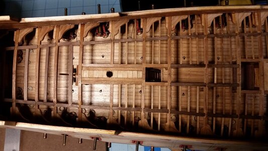
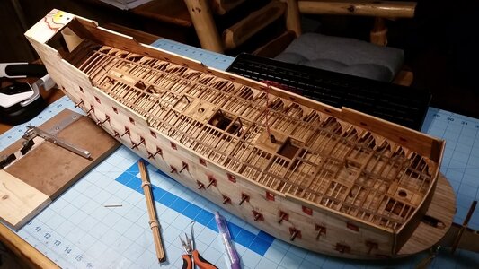
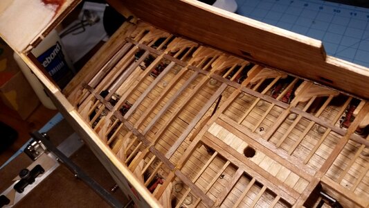
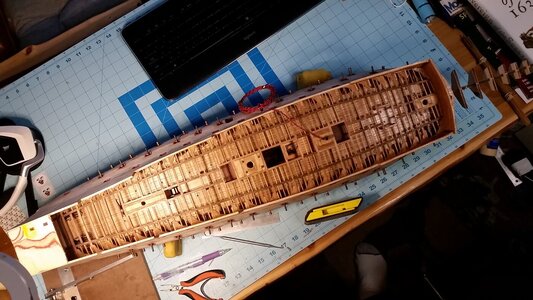
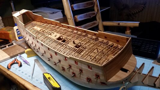
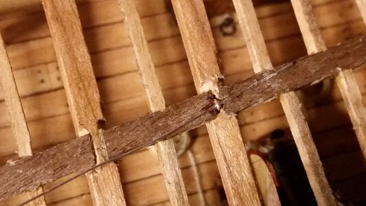
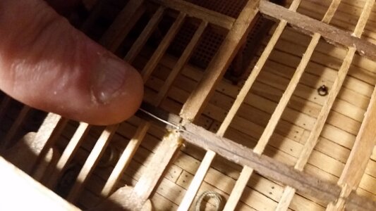
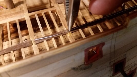
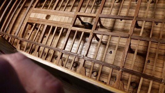
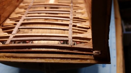
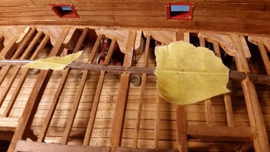
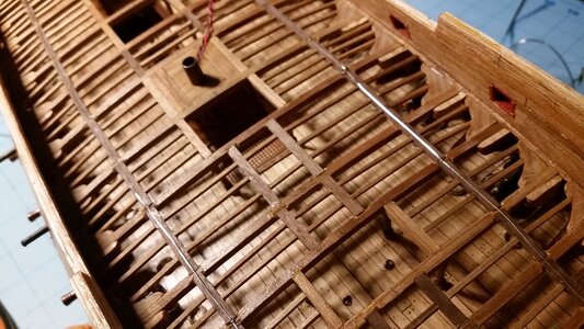
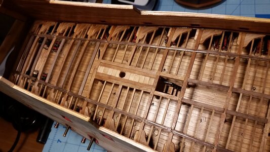
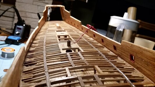
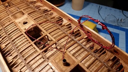
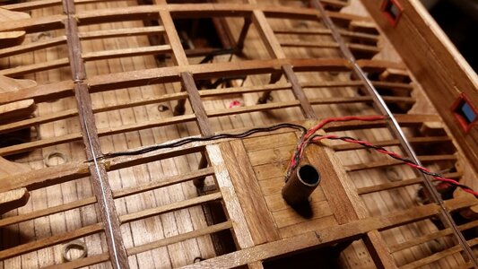
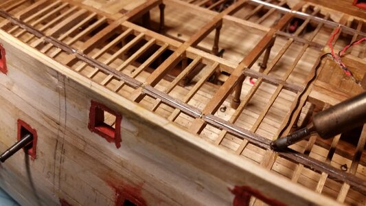
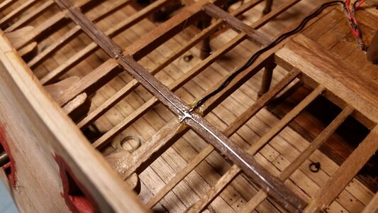
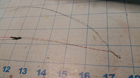
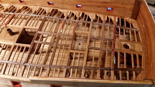
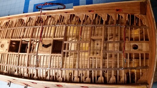
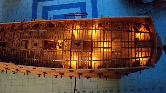
A lot of LED's were installed today. I ran out of nano yellow LED's and had to order more from Evan's Designs in order to continue work, but this is how far I got. These tiny yellow LED's are a simple way of simulating lanterns hanging from the beams overhead.
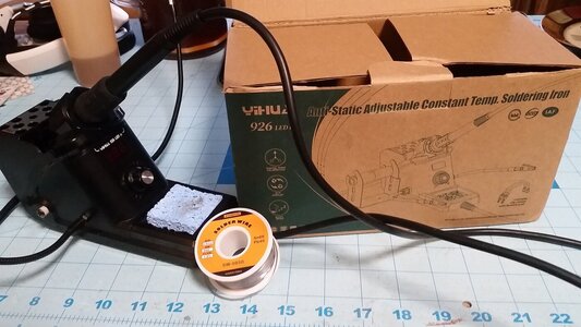
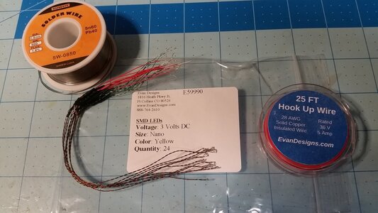
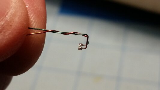
Here are the LED's, wire, and the solder that will be used. The LED's are only 1mm wide.
View attachment 314827
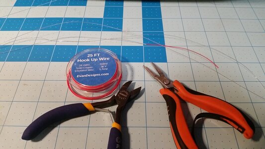
Two lengths of 24 gauge wire, each as long as the deck, are carefully stripped of insulation. These will be two long conductors running over the beams along the outboard carlings from bow to stern. The port side conductor will be positive, and the starboard one negative.
View attachment 314828
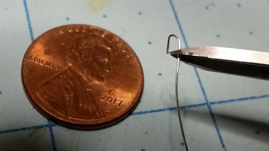
To hold the wire conductors to the beams, 24 gauge wire staples are made using a needle nose pliers.
View attachment 314829
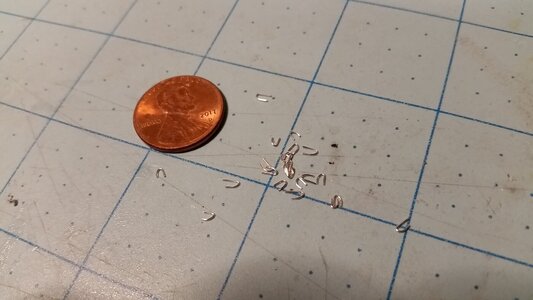
Here is a pile of staples ready for use.
View attachment 314830
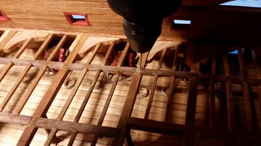
A tiny drill is used in a battery powered Dremel tool to drill two small holes for the staples in beams every 8 cm along the carling.
View attachment 314831
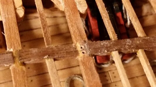
Holes for the staple.
View attachment 314832
Starting with the starboard (negative) conductor, the first staple is secured over the conductor near the bow with CA glue.
View attachment 314833
The next staple is inserted and glued in place.
View attachment 314834
Each staple must be held down until the CA glue cures.
View attachment 314835
Keep stapling the conductor every 8cm until you reach the end of the deck at the stern
View attachment 314836
The end of the conductor is secured simply by bending the end down and gluing it into a drilled hole at the stern.
View attachment 314837
Since the wires are springy and hard to manage, use masking tape to hold loose wire in position as you work. Here, masking tape is also used to hold a staple in place until the CA cures.
View attachment 314838
Here is a view of both conductors near the bow.
View attachment 314839
Conductors near the stern.
View attachment 314840
Overall view of the deck structure and the conductors in place.
View attachment 314841
The two remaining circuit wires are separated. The one reserved for powering lights in the stern in coiled up and set aside. The wires for this deck's lights is trimmed and made ready to solder to the two conductors.
View attachment 314842
The positive and negative wires are routed the conductors, red to positive, black to negative, and trimmed to length. The bare ends of the wires are held down by the conductor wires.
View attachment 314843
The power wires are soldered to the conductors.
View attachment 314844
Finished solder connection. The soft, flux core solder makes this very easy and quick.
View attachment 314845
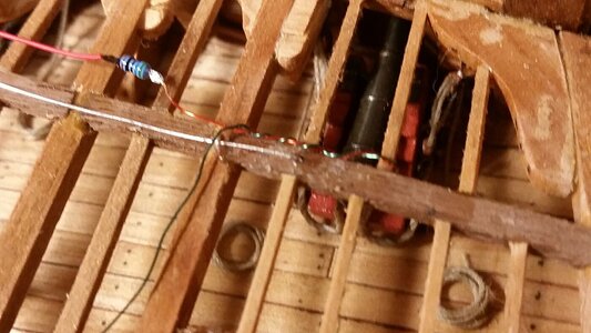
Each LED has a resistor on the positive lead, covered with shrink tube. The leads are untwisted, leaving 1cm of wire twisted just in front of the LED. If you untwist all the wire, one of the leads will break off the LED, ruining it. The shrink tube on the resistor will be removed using a razor knife, because in most cases, the resistor will have to be repositioned to some other location on the positive lead. This location is determined for each individual LED as you install them. The resistors are glued to the sides of the beams, because they are too thick to fit between the false deck and the beams later in the build. The wires are thin enough to fit between the false deck and beams without distorting the deck to any significant degree.
View attachment 314846
Each LED will wrap around a beam or a ledge. To help hold them in place, they are hooked around the beam, and glued in place with the LED facing downward.
View attachment 314847
It's hard to see here, but the LED is wrapped around a ledge with a bit of glue holding it in place, and the positive lead and resistor are still loose. The negative (green) lead is routed to the other side of the ship toward the negative conductor. The LED is out of view, under the carling, and facing down to shine on the middle gun deck below.
View attachment 314848
The first three LED's are installed. Each of the wires and resistors in held in place with spots of PVA glue, which appear invisible except for the wet glue covering the resistor from the center LED located one beam forward of the main hatchway, which appears yellow-white.
View attachment 314849
The first 8 LED's in the forward section of the ship are installed. All the wires on top of the beams were carefully straightened and tacked to the beams in several spots using PVA glue. The edges of the false deck sections will be positioned on either side of the wires wherever possible to reduce gaps between the false deck and the beams below to a minimum.
View attachment 314850
The AC transformer is plugged into an outlet, and the DC plug is plugged into the socket on the bottom of the model. The adjacent switch on the bottom of the hull is turned on, and the lights are tested. Success! Every light works. More LED's will be installed all the way to the stern when they arrive in the mail.
View attachment 314851
 . It is super interesting to see a ship construction being made in miniature. Fantastic work. Cheers Grant.


