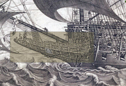
HMS Sovereign of the Seas - Bashing DeAgostini Beyond Believable Boundaries

After you complete all this wonderful work do you have to replicate it for the starboard side?
Yes. Most of the decorations will be mirrored to the starboard side, but many are unique, such as the zodiac icons. Despite most of the historic sources only showing one side of the vessel, Hendrik Busmann provides clues to which zodiac icons should be used on the starboard side in his book "Sovereign of the Seas. Die Skulpturen des britischen Königsschiffes von 1637".
1745754527628.png
 
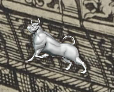
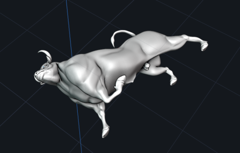
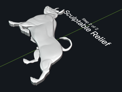
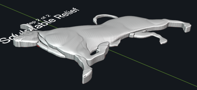
I'm trying out a new tool today. After scupting a the black bull object to the correct pose, I bought a new Blender add-on plugin called Basify which converts 3-D objects in to base reliefs. This is my first attempt to use it. First, I starting with my 3-D object, which is very thick.
1746391762971.png1746391801257.png

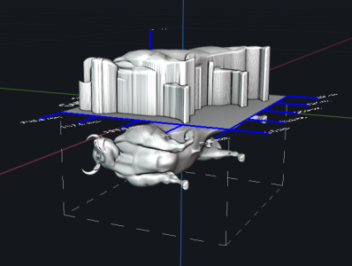
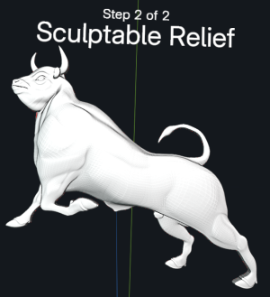
Then I use Basify to create a base relief. You place your object inside a box under a plane that is bereated by the add-on, adjust a few variables, and you get a base relief. The object under the plane can be positioned an any angle. Note how tall the base relief is compared to the original object beneath it. It had to be extrude that too to preserve the depth and details of the head and muscles. I'm going to fix that.
1746391896860.png1746391920888.png

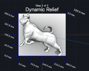
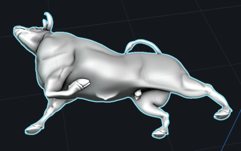
The add-on creates a copy of the base relief to another location so you can sculpt and edit it. Let's thin out the model by editing the legs and other parts to move them upward and more in line with the main body. There.. that's much better.
1746392269605.png1746392417869.png

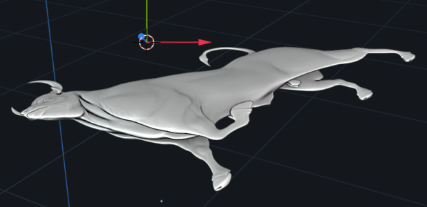
Compare that to simple flattening the original 3-D object:
1746392531062.png

Looks a bit too flat to print on the resin printer. Which do you guys like better?
1746393014017.png1746393177251.png
 
I'm trying out a new tool today. After scupting a the black bull object to the correct pose, I bought a new Blender add-on plugin called Basify which converts 3-D objects in to base reliefs. This is my first attempt to use it. First, I starting with my 3-D object, which is very thick.
View attachment 517748View attachment 517749

Then I use Basify to create a base relief. You place your object inside a box under a plane that is bereated by the add-on, adjust a few variables, and you get a base relief. The object under the plane can be positioned an any angle. Note how tall the base relief is compared to the original object beneath it. It had to be extrude that too to preserve the depth and details of the head and muscles. I'm going to fix that.
View attachment 517750View attachment 517751

The add-on creates a copy of the base relief to another location so you can sculpt and edit it. Let's thin out the model by editing the legs and other parts to move them upward and more in line with the main body. There.. that's much better.
View attachment 517755View attachment 517756

Compare that to simple flattening the original 3-D object:
View attachment 517757

Looks a bit too flat to print on the resin printer. Which do you guys like better?
View attachment 517758View attachment 517759

Im not sure how to comment or reply to all this computer graphics your creating. It's something I'll never get into other than very basic photoshop but I watch this thread in total facination and amazement. To me it's like Sci-Fi version of art in modelling, perceverence and achievement. Kudos Thumbsup
 
Im not sure how to comment or reply to all this computer graphics your creating. It's something I'll never get into other than very basic photoshop but I watch this thread in total facination and amazement. To me it's like Sci-Fi version of art in modelling, perceverence and achievement. Kudos Thumbsup

Ditto….
and way beyond my pay grade but incredibly well done models (objects?).
 
The 3-D object LOOK good so far, but will they resin print? That's the next hurtle to jump once all the objects are created.
You raise an interesting point. Would it not be preferable to print a few to see how they turn out, rather than put all that work into design only to find out there was a problem lurking there somewhere that would require a major rework?
 
You raise an interesting point. Would it not be preferable to print a few to see how they turn out, rather than put all that work into design only to find out there was a problem lurking there somewhere that would require a major rework?
There WILL be an adjustment period, where several objects will need to be reshaped or changed and reprinted. That's to be expected, especially since I'm new to this, and have all the beginner mistake yet to make. All the Blender scene files are save as well the objects themselves. So, object edits can be made. Unfortunately for all your wood carvers out there, mistakes can't usually be undone. 3-D printing has an advantage there.
 
Kurt - all of this is incredible and your 3-D digital modeling skills are improving leaps and bounds.

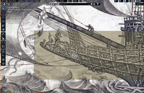
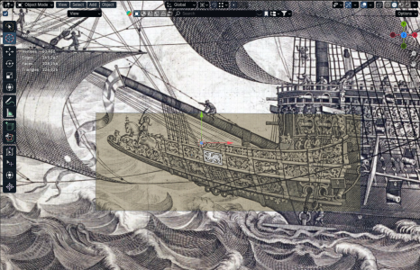
The challenge that occurs to me with this ornamental endeavor is that your carving models are all based on the layout and variable depth perspective of the Payne engraving, as opposed to a scale plan view.

You can, of course, re-scale individual carvings, as needed, but the compartmentalization of your model framing elements - all of the horizontal drifts and vertical moulds of the upper bulwarks - will have to pretty exactly mirror those angles and attitudes of the engraving.

I think there are ways to go about this. For example, you could place the carvings on the model, first, in broadside courses working from lowest to highest. Then, you could add your horizontal drifts above and below each ornamental belt.

The main deck gun-port spacing is what determines the placement of the vertical moulds. What I’m puzzling over is how to match the angles and dimensional parameters of the carving grounds you designed with the spaces available on the actual model.
 
Is there a way to digitally correct the Payne engraving’s isometric perspective into a plan view that exactly matches the scale parameters of your as-built model? This might save you a lot re-work later. I acknowledge, in advance, that you may have already addressed these issues in the log, which I have not read in its entirety.
 
Kurt - all of this is incredible and your 3-D digital modeling skills are improving leaps and bounds.

The challenge that occurs to me with this ornamental endeavor is that your carving models are all based on the layout and variable depth perspective of the Payne engraving, as opposed to a scale plan view.

You can, of course, re-scale individual carvings, as needed, but the compartmentalization of your model framing elements - all of the horizontal drifts and vertical moulds of the upper bulwarks - will have to pretty exactly mirror those angles and attitudes of the engraving.

I think there are ways to go about this. For example, you could place the carvings on the model, first, in broadside courses working from lowest to highest. Then, you could add your horizontal drifts above and below each ornamental belt.

The main deck gun-port spacing is what determines the placement of the vertical moulds. What I’m puzzling over is how to match the angles and dimensional parameters of the carving grounds you designed with the spaces available on the actual model.
The ornaments are indeed skewed to the curve of the sheer. If they were rectalinear, they would not fit the curves of the ship. Of course, the amount of sheer each ornament has varies depending on its position on the hull, all in accordance with the Payne engraving. The amount of curvature in each model is estimated from the perspective displayed in the engraving as much as possible, but without any precise measurements being taken.

The framework of horizontal mouldings and column will need to be placed onto the hull first. This will establish the size and shape of each of the decoration pieces. The locations of the gun ports do determine the column locations.

In Blender, the "shear" tool can skew a 3-D object quickly and easily to make adjustments. The models can be stretched on the X and Y axes as well if needed, and distortion will be minimal. All of them will need to be printed, test fit, and the models adjusted and re-printed. That's to be expected when delving into this type of work when one has never done it before.
 
Is there a way to digitally correct the Payne engraving’s isometric perspective into a plan view that exactly matches the scale parameters of your as-built model? This might save you a lot re-work later. I acknowledge, in advance, that you may have already addressed these issues in the log, which I have not read in its entirety.
You could never get the proportions of the engraving image to match the model and have every detail line up perfectly. You would have to adjust each decoration's size, proportion, and skew angle anyway. So, the decorations will be adjusted to fit the model, as defined by the gunport and deck positions. It should all come together just fine in the end with careful measurement and placement of the border columns and mouldings.
 
Back
Top