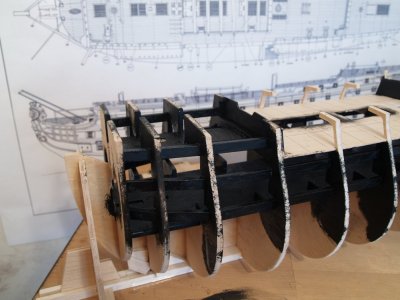
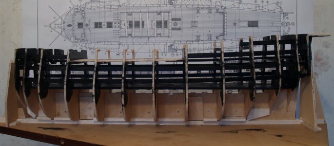
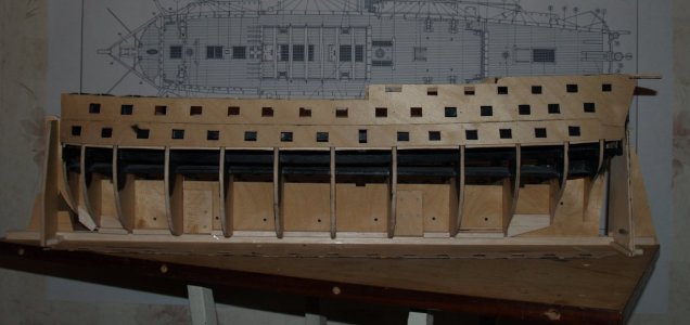
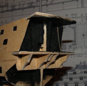
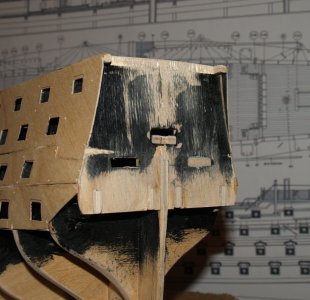
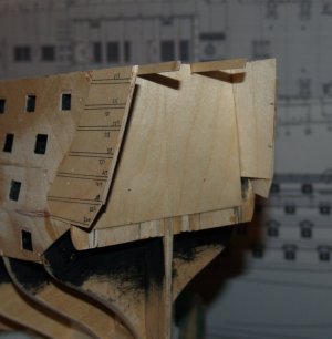
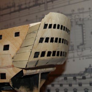
HMS Victory [1805] 1:79 by serikoff. Started with Mantua -> Upgraded with John McKay's Anatomy.

Joined
Oct 1, 2024
Messages
652
Points
393

Location
Ukraine, Kyiv
Hello to all my colleagues in the best hobby in the world!

My name is Sergey, but in the world of ships, I go by the name serikoff.

And here’s my story. (Without this introduction, it might be hard to understand me).

I’m from Ukraine and I am the creator of a website and forum dedicated to wooden shipbuilding. My forum is one of the largest in Ukraine. It began functioning fully in 2012. There are more than 150 build logs, just as many threads featuring completed models, and 250 threads discussing techniques and other topics. Some of the modelers who have published their work include prominent names such as: Evgeny Epur, Dmitry Shevelev, and Vladislav Zhdan. These names are well-known in our region. (By the way, Olga, who is known here under the nickname shipphotographer.com, also regularly published her work. It’s not surprising, since we’re from the same area). But! The situation started to deteriorate after 2014, when we began having issues with the website’s domain and hosting. That was the first phase of the war, as our countries were closely intertwined, and cross-sanctions began to destroy joint services. And after the full-scale Russian invasion of Ukraine, the website essentially died. To be more precise, it still exists, but all the images uploaded by modelers have disappeared. The reason for this is a conflict between the image storage resources and the website’s platform. Right now, I don’t have the resources or time to restore it. But I’m sure that after our victory, someone will be able to create a forum as large and wonderful as yours.

Now, about me...

I started building my second model in 2009 (the first one was experimental, and I didn’t see the point in finishing it). At that time, there weren’t as many resources available as there are today. I made many mistakes and learned how to correct them. I shared this knowledge on my website and forum. However, due to being busy in 2013, I had to put my project on hold. But as the saying goes, "Every cloud has a silver lining." The war started, borders were closed, and I could no longer travel—something that took up all my free time. I’m a dentist, in case anyone’s curious. And under constant shelling, explosions, and air raid sirens, to keep from losing my mind, I decided to return to my hobby. Exactly 10 years later.

What am I doing here...

First of all, I’d like to say that I found your forum by accident. But! I fell in love with it right away! There’s a warm atmosphere, lots of information, and I’ve really been missing all of this. In my journal, I want to share my build, all the knowledge I have, and, of course, ask the questions that interest me. I will be happy to help anyone if you have questions, feel free to reach out. I’m deliberately not posting a link to my website so as not to spoil the build. I want my journal to progress in real time, reaching the current state of the build. Please excuse my English—I will be using Chat GPT for translations to avoid any difficulties.

What I’m building...

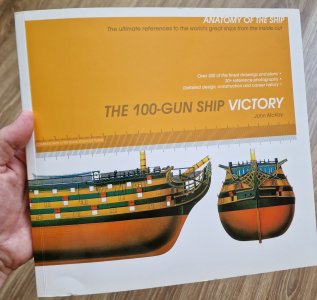
As you can see from the title, it’s HMS Victory. I created the framework of the model using plans from a Mantua kit. I didn’t buy the kit itself. I printed the plans in A0 format and built the frame (the skeleton) based on them. That was the end of my work with the Mantua kit. All further work was based on John McKay’s anatomy of the ship. In this journal, I want to take you through the whole process, from the kit plans to the anatomical upgrade.
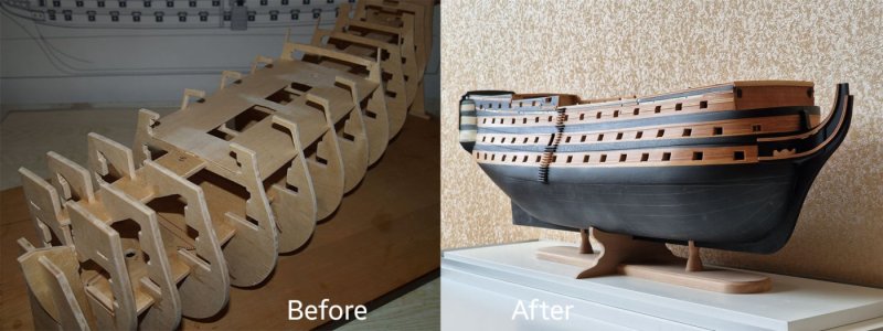
01 До после.jpg

I would also like to share my experiments: Working with blueprints. Aging and painting wood. Aging copper. Making and painting ropes and rigging. 3D modeling and integrating 3D printing into wooden shipbuilding. And much more. It will be fun, and I hope it will be informative for you. I’m sure I will learn a lot from you as well. Thanks in advance for that!
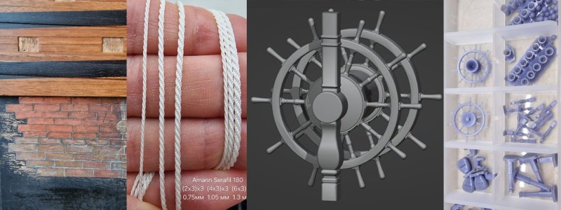
02 что.jpg

Let’s get started!

P.S. Рідною.

Хочу звернутися до всіх українців, що виїхали до, чи під час війни. Не слухайте нікого. Кожна людина прагне щастя та безпеки собі та своїм близким. І я щиро сподіваюся, що у вас все добре і ви у безпеці. А всім, хто залишилися, хочу побажати перемоги, мирного неба, сил та здоров'я все це пережити. Бережіть себе, все буде Україна! Слава ЗСУ!
 
Part 0

And of course, I'll start with the blueprints. As I mentioned above, I used the plans from the Mantua kit as the basis for the frame. However, I want to note that if you're planning to build this model, make sure to work with better-quality blueprints than those provided in the kit. Don’t repeat my mistakes. My excuse is that I started building in 2009, when I was practically a beginner, and at that time, these were the only complete plans I could find. Nowadays, I would use more accurate frame plans, but it is what it is.

This post is more for those who bought the Mantua kit, and I can point out the problems, errors, and inaccuracies in the blueprints for you. Details are shown in the images below.

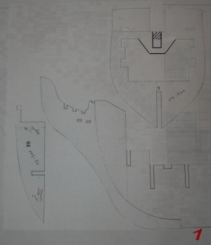
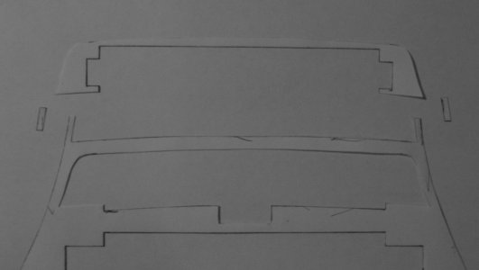
In Figure 1, part 25, it's better to cut off the knee of the head, creating a recess to install it later. It will get in the way when you're planking, and it certainly shouldn’t be made from plywood. And for part 1, you’ll need to create space for the bowsprit, as this wasn’t accounted for in the plans, and you’ll end up cutting into the hull later.
01.jpg

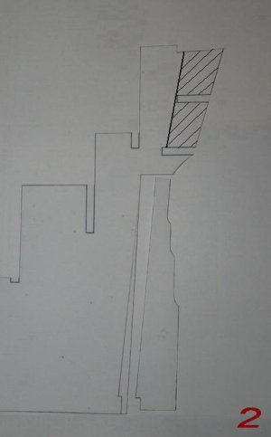
In Figure 2, you can see how the sternpost (the piece to which the rudder is attached) should look, as well as the rudder itself.
02.jpg

In Figure 3, you can see the part that will become the hull side—it has been reduced in thickness. This applies to the 8th and 9th frames.
03.jpg

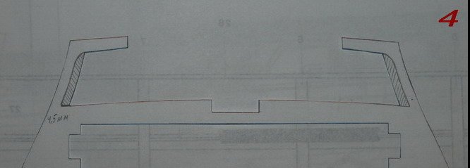
The 5th, 6th, and 7th frames will be modified as shown in Figure 4.
04.jpg

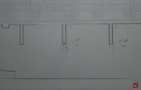
Now, about the discrepancies. In Figure 5, it shows how much you need to shift the cutout for the 4th and 5th frames—by 1.5 mm and 0.7 mm towards the rear.
05.jpg

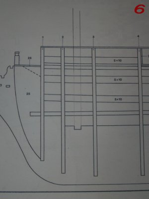
As is known, a ship's masts are not like houses; they are not always at a 90-degree angle to the horizon (from the side). On the Victory, only the forward foremast is vertical, as indicated in Figure 6...
06.jpg

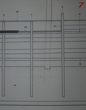
The main mast has a tilt of 2 degrees, as shown in Figure 7.
07.jpg

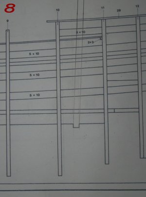
The mizzen mast is tilted even more—3 degrees towards the rear, as shown in Figure 8.
08.jpg

So, it turns out that there are no problems at the front; all the holes are in place and everything aligns correctly (see Figure 9).
09.jpg

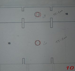
However, moving on, it gets more complicated. In part #15, the hole has shifted by 1 mm, while in part #16, it has shifted by a full 3 mm (see Figure 10).
10.jpg

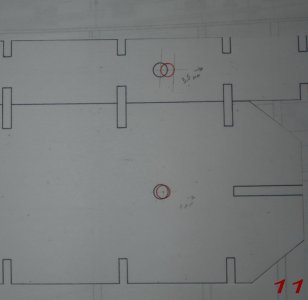
Similarly, at the rear of these parts, the holes have shifted by 1 mm and 3.5 mm, respectively (see Figure 11).
11.jpg

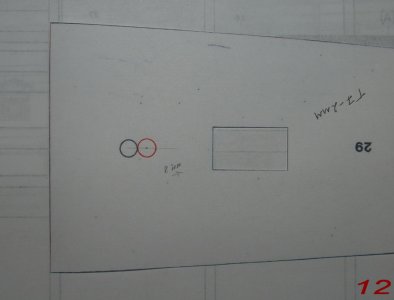
Even higher (in part 29), there is an even greater deviation—by a whole mast body, 8 mm (see Figure 12).
12.jpg

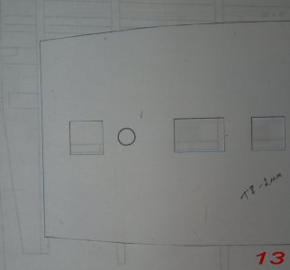
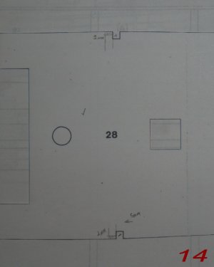
But the most interesting thing happened with part 28. Here, all the holes align correctly, taking the tilt into account! (see Figures 13 and 14)...
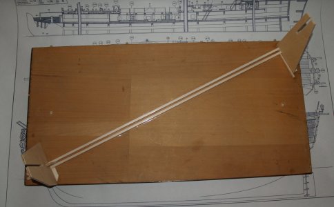
13.jpg
14.jpg
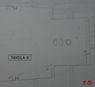
However, there is a complete misalignment at the rear. It extends by 5.5 mm and 6.5 mm into the 10th and 11th frames. Therefore, the areas marked with a pencil need to be removed (see Figure 15). The slots for the 8th and 9th frames are also misaligned, but even without that, they need to be cut only 2 mm deeper and 5 mm forward from the incorrect position (see Figures 14 and 15).
15.jpg

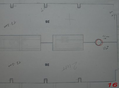
The same problem exists with the lower deck (see Figure 16). The hole is off by 2.5 mm towards the rear, and the slots need to be cut only 5 mm deeper (under the cut for the frame, see Figure 4).
16.jpg

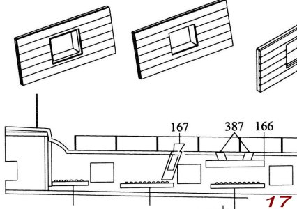
Additionally, the blueprints do not include parts #167 and #387 (from the JoTiKa plans), which are actually very important! Furthermore, the ports are not indicated as being different. In Figure 17, you can see that the left port is designed for a door that fits into the groove, while the right one does not have this door, and the groove (the frame around the opening) is unnecessary.
17.jpg

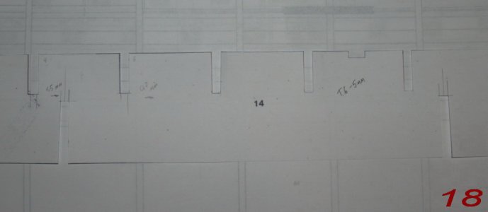
I would also like to return to the hull, specifically to part #14. In advance, I prepared grooves for the base on which the model will stand (see Figure 18).
18.jpg

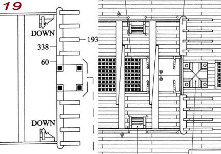
I also wanted to point out this discrepancy with the original. The ladder that descends to the lower deck in the blueprints (on the right) is one flight further from the bell tower. However, it should correctly be in the first flight (on the left). The second pair is positioned correctly (I haven't depicted them) (see Figure 19).
19.jpg

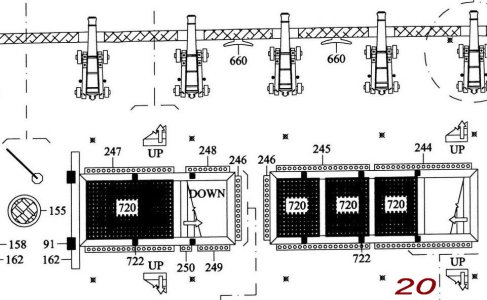
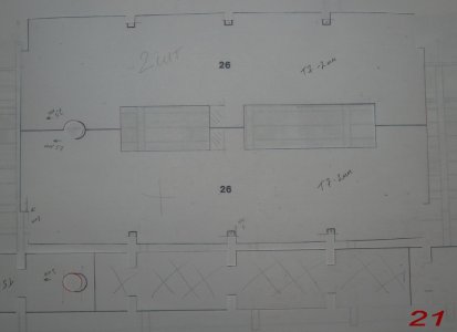
Additionally, the Mantua blueprints do not include parts #660, #162, and #244-247, as indicated in Figure 20 of the JoTiKa plans. Furthermore, the left hatch is longer. I have corrected this, as shown in Figure 21. As for the simplification that Mantua made by removing the ladder to the lower deck and replacing it with doors, I will not be doing that. Both ladders will remain! Consequently, part #16 will be reduced in size. From the 4th to the 8th frames, there will be an interruption in part #16, as indicated in Figure 21.
20.jpg
21.jpg

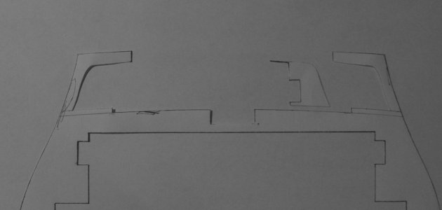
To ensure that parts #27 are not visible through the middle deck, I extended the lower deck by one more cannon on each side (I will detail this in the second part of the review). As for the blueprints themselves, I made the following adjustments: in frame #4, I cut out the inner part (similar to frame #5), and in frame #8, I did it as shown in the second photo. For those who will do the same but with the benefit of experience, it's better to initially calculate the deck to be longer, ideally to its full length, as this would be the correct approach.
22.jpg
23.jpg

During the manufacturing process, I made some additional adjustments that I will not duplicate here. Therefore, if you are building the same model, I strongly recommend reading the entire review thoroughly from the beginning to ensure that everything is done correctly.

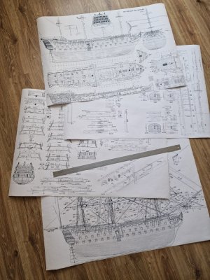
I will only add four sheets of blueprints at a 1:1 scale, each sized A0. This scale is tailored to the dimensions of my specific model—i.e., the size that resulted from the initial construction of the skeleton hull based on the Mantua blueprints!
HMS Victory 189.jpg
HMS Victory 191.jpg

These blueprints (four sheets) were created from scans of the anatomy book (which I purchased) by combining them in Photoshop, calibrating all the plans to a common standard. I understand that this is complicated to explain and can be difficult to grasp, but the important thing is that it all worked for me! The proportions and dimensions all matched, except for a small section that I will mention in the review. For reference, I am sharing these blueprints here. If I were doing this now, I would create not only these four sheets but also the frames for building the skeleton hull. However, since I already have the hull, I made these four sheets, which illustrate all the other parts I need, such as useful items, rigging, and, most importantly, the proportions of where everything should be located. This is necessary because the simplified Mantua blueprints are lacking in this regard.

I hope this has been useful to you, and if there’s anything to add, feel free to write here. I will try to upload the full-size photos (7000 x 5000 pixels) here.
 
Welcome aboard, Sericoff!
During the difficult times in your Country, we invite all of your forum members to join us. As you have already found, the warm and friendly atmosphere in our Forum. We are an international forum, and have members from around the globe.
 
Thanks for sharing these. I am sure it took you not one day of work to compile them. I would say a couple of weeks?
Yes, you're right, it wasn’t quick. But I would have done the entire anatomy and all the hull fragments. However, by the time I got to that point, I already had the hull ready. And soon, all of this will be shown here.
 
Part 1
So, let's start with the build log of the model…

10.2009
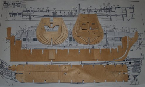
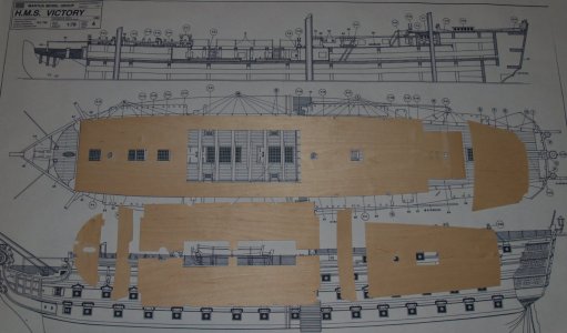
After thoroughly studying and refining the plans, I searched for high-quality multi-layered plywood with a thickness of 5.5 mm.
I ordered 2 mm plywood from a local store.
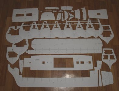
Once I found suitable plywood, I started transferring all the profiles from the paper.
HMS Victory 000.jpg

After that, a long task lay ahead—cutting out each part. I started with the 5.5 mm plywood...
HMS Victory 001.jpg

... and then with the 2 mm plywood.
HMS Victory 002.jpg

11.2009
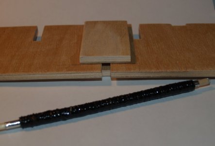
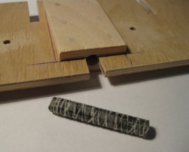
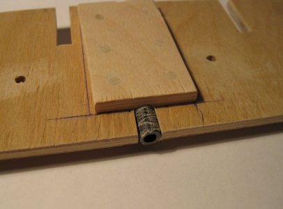
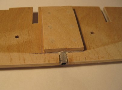
For the future mounting of the model to the stand, I cut two slots, each 6 mm wide. I reinforced this area on both sides with plywood plates. Inside, I placed a cylinder filled with epoxy-soaked threads. Later, a bolt from the stand will be screwed into this cylinder.
HMS Victory 003.jpg
HMS Victory 004.jpg
HMS Victory 005.jpg
HMS Victory 006.jpg

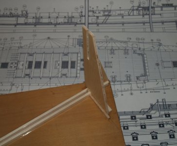
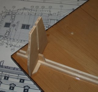
Once all the parts were ready, I created a simple slipway. Plywood tends to warp with humidity changes. And for precise assembly, we need the entire structure to be rigid, with all parts positioned at exactly 90 degrees.
HMS Victory 007.jpg
HMS Victory 008.jpg
HMS Victory 009.jpg
...
 
11.2009
For 12 hours straight, not a minute less, I worked on the hull. Glue in hand, excitement in my eyes, and by night (having started in the morning), I had a completed hull in front of me.
Now, let’s go step by step.
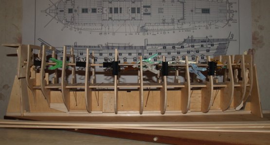
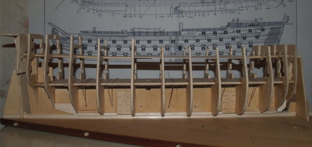
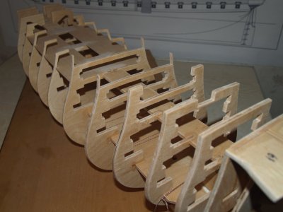
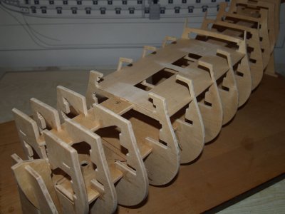
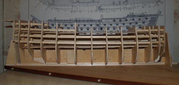
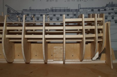
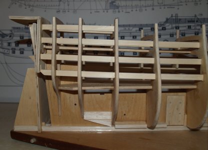
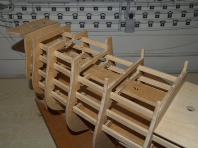
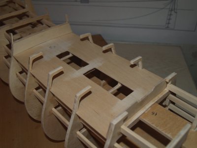
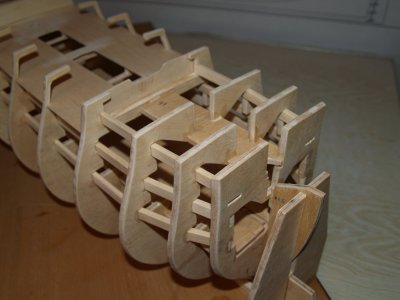
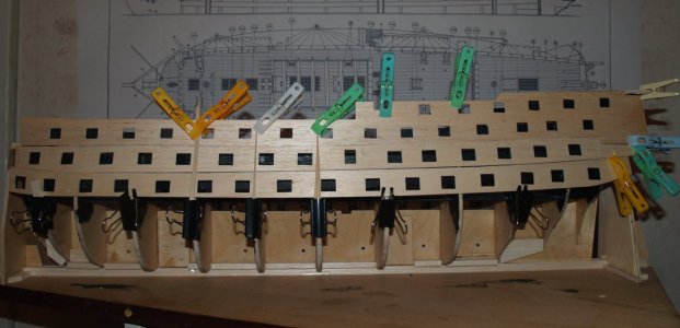
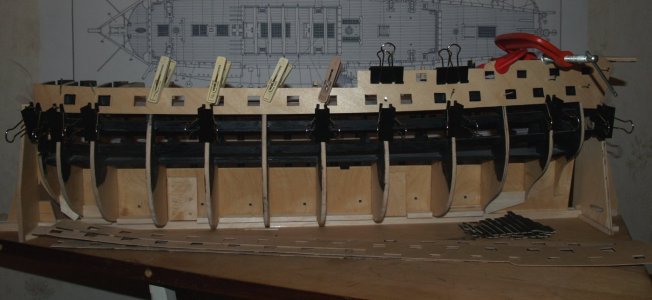
First, I placed the keel into the slipway. I installed all the frames, gluing them in place. After reinforcing them with parts No. 15 and 16 and installing the decks (to check for any misalignment), I generously applied PVA glue.
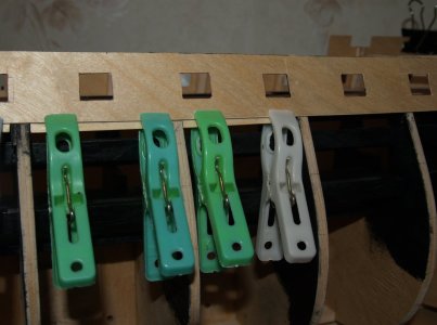
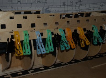
As you can see, my clamps were nothing fancy: regular clips, clothespins, and string threaded through pre-drilled holes. I also installed spacers along the entire perimeter of the keel. This added extra rigidity and ensured the keel wouldn’t warp. For spacers, I used balsa wood 6x150 mm, placed between each frame on both sides.
HMS Victory 010.jpg
HMS Victory 011.jpg

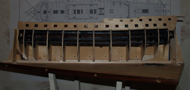
When the glue dried, this is what I ended up with!
HMS Victory 012.jpg
HMS Victory 013.jpg
HMS Victory 014.jpg

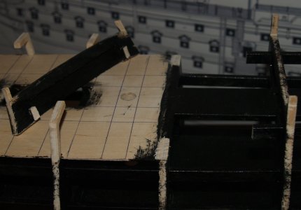
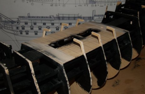
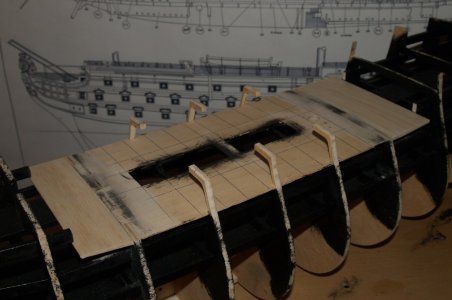
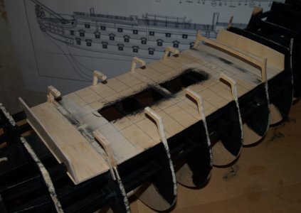
Next, without wasting time, I got to work on the false gun rails. These are strips measuring 5x10 mm that needed to be glued into the grooves of the frames. I did this by holding the bend in place with regular thread, tying the strips to the frames.
HMS Victory 015.jpg

At the front and back, it was impossible to achieve the curvature, so the strips in the front and rear frames were cut and bent to the desired shape.
HMS Victory 016.jpg
HMS Victory 017.jpg

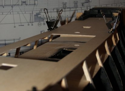
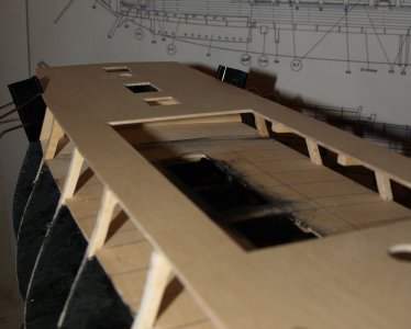
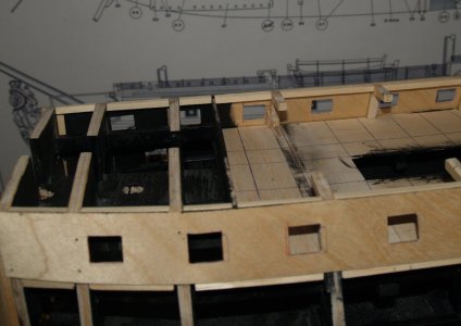
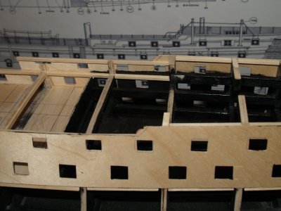
I also glued the side walls for the lower deck.

P.S. I want to mention in advance that I extended the lower deck, so these walls will be fixed in a different location than you see here. To do it right from the start, scroll a bit further ahead. Overall, I recommend making this deck completely, i.e., without false cannons. The deck level is marked on all frames... In other words, do it the way Jotika suggests. I would have done that, but it is what it is.

By the way, in places where the hatches are located, the frames need to be trimmed (specifically the 5th, 7th, and 11th frames). However, do not cut the area for part No. 16 in the 6th frame, as this is where the two sections of the lower deck connect.
HMS Victory 018.jpg
HMS Victory 019.jpg
HMS Victory 020.jpg
With euphoria in my heart, I barely fell asleep after the work I had done. The thought of painting tomorrow kept me wide awake.
(Oh, by the way! What you see now consists of 91 parts. Just for the record.)

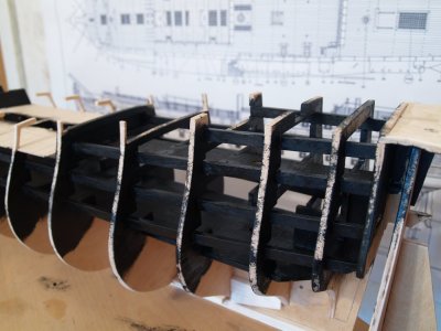
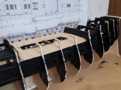
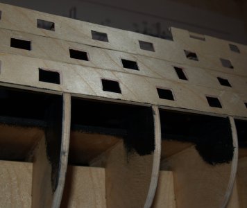
I didn't expect the paint to take so long to dry. But patience is running out, so I took a photo as it is. The paint is matte to avoid any shine. In reality, after drying, there was no gloss at all.
HMS Victory 022.jpg
HMS Victory 023.jpg
HMS Victory 024.jpg
HMS Victory 021.jpg

The total number of parts at this point is 100.

To be continued...
 
11.2009
For 12 hours straight, not a minute less, I worked on the hull. Glue in hand, excitement in my eyes, and by night (having started in the morning), I had a completed hull in front of me.
Now, let’s go step by step.
First, I placed the keel into the slipway. I installed all the frames, gluing them in place. After reinforcing them with parts No. 15 and 16 and installing the decks (to check for any misalignment), I generously applied PVA glue.
As you can see, my clamps were nothing fancy: regular clips, clothespins, and string threaded through pre-drilled holes. I also installed spacers along the entire perimeter of the keel. This added extra rigidity and ensured the keel wouldn’t warp. For spacers, I used balsa wood 6x150 mm, placed between each frame on both sides.
View attachment 476036
View attachment 476037

When the glue dried, this is what I ended up with!
View attachment 476039
View attachment 476040
View attachment 476041

Next, without wasting time, I got to work on the false gun rails. These are strips measuring 5x10 mm that needed to be glued into the grooves of the frames. I did this by holding the bend in place with regular thread, tying the strips to the frames.
View attachment 476042

At the front and back, it was impossible to achieve the curvature, so the strips in the front and rear frames were cut and bent to the desired shape.
View attachment 476043
View attachment 476044

I also glued the side walls for the lower deck.

P.S. I want to mention in advance that I extended the lower deck, so these walls will be fixed in a different location than you see here. To do it right from the start, scroll a bit further ahead. Overall, I recommend making this deck completely, i.e., without false cannons. The deck level is marked on all frames... In other words, do it the way Jotika suggests. I would have done that, but it is what it is.

By the way, in places where the hatches are located, the frames need to be trimmed (specifically the 5th, 7th, and 11th frames). However, do not cut the area for part No. 16 in the 6th frame, as this is where the two sections of the lower deck connect.
View attachment 476046
View attachment 476047
View attachment 476048
With euphoria in my heart, I barely fell asleep after the work I had done. The thought of painting tomorrow kept me wide awake.
(Oh, by the way! What you see now consists of 91 parts. Just for the record.)

I didn't expect the paint to take so long to dry. But patience is running out, so I took a photo as it is. The paint is matte to avoid any shine. In reality, after drying, there was no gloss at all.
View attachment 476049
View attachment 476050
View attachment 476051
View attachment 476052

The total number of parts at this point is 100.

To be continued...
Hello Sergey
Definitely a good start on the skeleton.
I'll follow your build with great interest as Victory is my next ship.
Cheers
 
Hello Sergey
Definitely a good start on the skeleton.
I'll follow your build with great interest as Victory is my next ship.
Cheers
Great choice for your next project. I hope that through my work, I can help you avoid both my mistakes and any potential ones. Thank you, I’ll be looking for your current project as well.
 
A Victory in scale 1:79 - a relatively untypical scale - as I understood based on the Mantua model kit drawings, which is in 1:98

I am sure, that your log will be highly interesting to follow

and

like Jim already mentioned - please feel free to invite other modelers to join here to be part of our community
The scale is what it is because I printed A0 sheets in a size that was roughly suitable for me. That’s why it’s not the same as the standard Mantua scale. Later, I adjusted the scanned drawings from the anatomy book to fit my 1:1 size.

Yes, I’m almost certain it will be interesting.

I’ll send out a call and invitation to this community to my friends.
 
Part 2

11.2009


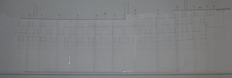
Until 6 a.m., I was calculating the placement of the gun ports, but still didn't manage to finish everything.
At first, I calculated everything on paper according to the drawings.

HMS Victory 025.jpg

But the drawing, as you understand, is a two-dimensional image, and when fitting them onto the model, some adjustments were made.
HMS Victory 026.jpg
HMS Victory 027.jpg

*By the way, I would like to point out that on the battleship, the gun ports are NOT the same size! They vary in dimensions (see image below).
HMS Victory 028.jpg

Only by morning did I manage to transfer everything from the templates to the wood. These are the so-called intermediate templates. I find balsa wood to be an excellent material for this, but cutting across the grain was quite a challenge. I had to cut along the grain first, then "crumple" it with some extra margin (that's the only way I can describe the process), and finally, finish it off with a file.
HMS Victory 029.jpg

In the end, here's what I got.
HMS Victory 030.jpg

Minor adjustments were made, and the topic was covered.
HMS Victory 031.jpg

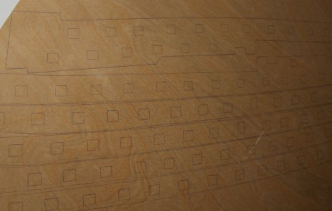
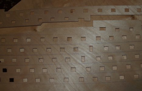
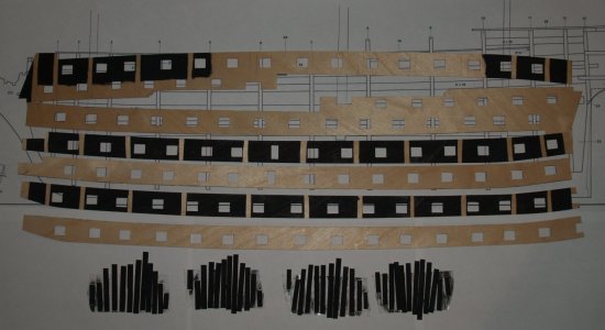
As you may have noticed, I didn’t choose the option of "poking" the gun ports into the finished planking. Instead, I preferred the method suggested by JoTiKa.
Yes, it took me a day and a half of calculations, but the result impresses me greatly. The main advantage of this method is that on the template, you can correct everything, bring it to perfect accuracy, and have access from the opposite side (to control the alignment of the gun ports with the planking for the cannons).
HMS Victory 032.jpg

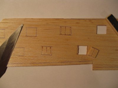
Next, I transferred everything onto plywood (1 mm, but I would recommend at least 1.5 mm). Then, I faced the task of cutting out the ports... cutting, cutting, and cutting some more. One huge advantage! This can all be done on the table in a comfortable position, rather than in the air with the model, constantly watching to make sure nothing gets damaged.
HMS Victory 033.jpg
...
 
11.2009

But before cutting out the ports, I made some initial changes. I noticed that when the upper deck is placed, the walls of the lower deck would be visible. So, I decided to move these walls one cannon port further out on each side.
HMS Victory 034.jpg
HMS Victory 035.jpg

I cut part of the frame, leveled the deck, and then added partitions and sections of the frames.
HMS Victory 036.jpg
HMS Victory 037.jpg
HMS Victory 038.jpg
HMS Victory 039.jpg

The result—I liked it. The walls are almost invisible. And the part that remains visible will cover the edge of the floor and the beams that will support the boats.
HMS Victory 040.jpg
HMS Victory 041.jpg
...
 
12.2009

After that, I returned to cutting out the ports.
HMS Victory 042.jpg

Then I painted the inner surface, except for the strips for the glue, as well as the reinforcing strips.
HMS Victory 043.jpg

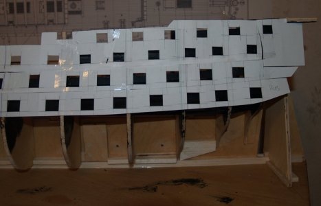
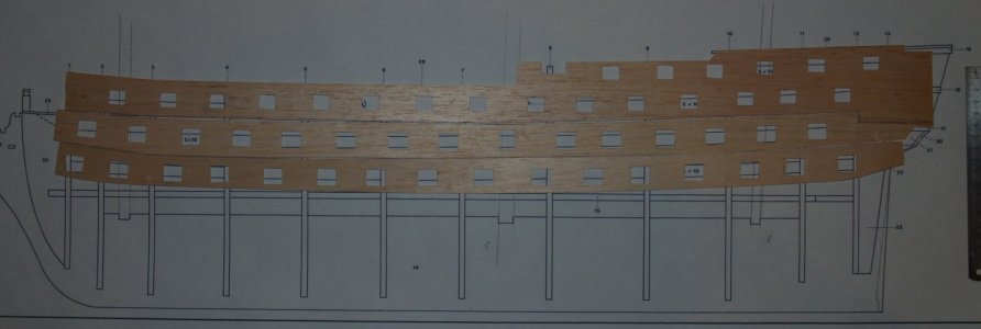
After the final adjustments, I started gluing these plates onto the hull.
HMS Victory 044.jpg

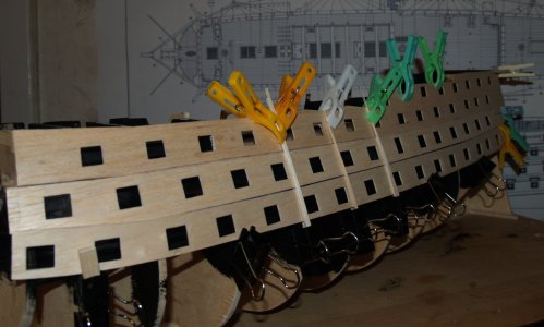
To strengthen the connection between the plates, I glued wooden inserts.
HMS Victory 045.jpg

I also reinforced the upper edges of the plates to prevent breakage.
HMS Victory 046.jpg
HMS Victory 047.jpg

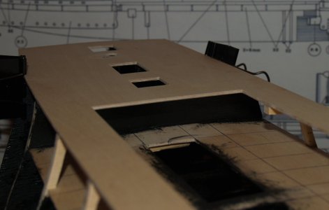
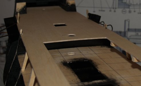
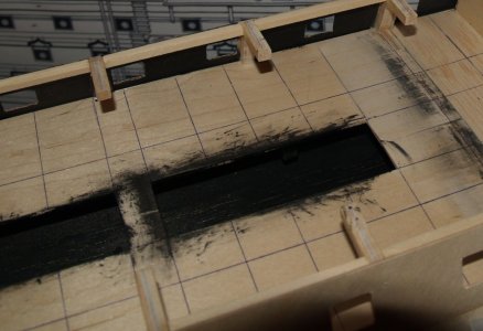
After that, while I had access to the very bottom deck, which was not included by Mantua, I glued in a simulated deck. I painted it black so that it wouldn’t be visible. The stairs will descend onto it. I installed these false decks onto pre-glued beams.
HMS Victory 048.jpg
In the photo, it's hard to see; everything is black. But that’s the plan. This joint will be better showcased later.

Then came the second belts with their inserts...
HMS Victory 049.jpg

...and the third. Here, I also reinforced the lower edge. This will ensure a good contact with the inserts that will cover the rest of the hull up to the keel frame.
HMS Victory 050.jpg

The final result will be in the next part.
This concludes the first part of the rough sheathing. There are 242 parts on board.
To be continued...
 
12.2009

So, the stern.
I can definitely say that the option suggested by the kit manufacturer, Mantua, was absolutely unsuitable for me!
HMS Victory 054.jpg

So, I cut that horror off to the root!
HMS Victory 055.jpg

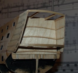
Armed with the drawings from Jotika, I cut a series of parts to assemble the stern frame. (I’ll repeat, at that time I still hadn’t realized that everything needed to be done according to the anatomy, but that will come soon). I left only the two side vertical walls. I decided to make the inner ones hollow and assembled. On the sides, there are tabs where the side part of the stern will be fixed.
HMS Victory 056.jpg

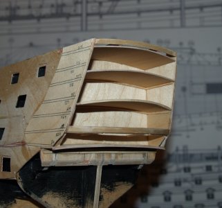
Then came the outlines. After calculating the stern's sag, I made them, along with the supports for the decks.
HMS Victory 057.jpg

After that, I could install the simulated decks. Additionally, in the last frame, I angled the lower edge to create a smooth transition from the stern section to the hull sheathing.
HMS Victory 058.jpg

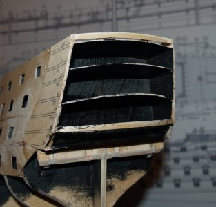
Then, I painted the interior...
HMS Victory 059.jpg

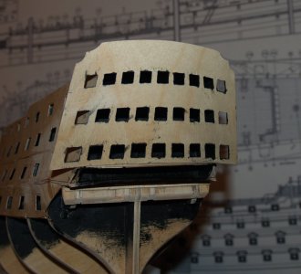
...and finally, I glued the front wall of the stern. This is just the rough frame; it will be covered with the finished cladding.
HMS Victory 060.jpg

The next step is the side parts of the stern.
...
 
12.2009

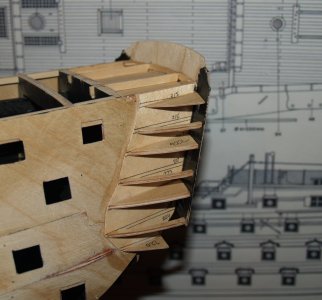
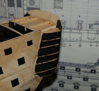
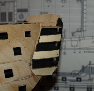
For five long days, work was carried out on the frame of the stern. The work on the side parts took a considerable amount of effort. First, I had to cut and glue the ribs. I borrowed them from the Jotika drawings, calculating the exact scale.
HMS Victory 061.jpg

Then, everything needed to be painted and left to dry completely.
HMS Victory 062.jpg

After that, individually calculate and glue the walls. First, the "balcony" walls, where the columns will be placed in the future...
HMS Victory 063.jpg

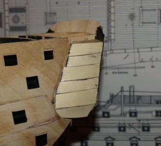
And then the "window" walls. I would like to note that they will remain solid only during the puttying and sanding process. After attaching the finish planking, holes will be cut into the "window" walls for the windows. More details will follow later in the review.
HMS Victory 064.jpg

Finally, the lower contours were added.
HMS Victory 065.jpg

That’s all for the stern section for now. Next up is the bow section.
...
 
Last edited:
Back
Top