• Win a Free Custom Engraved Brass Coin!!!
    As a way to introduce our brass coins to the community, we will raffle off a free coin during the month of August. Follow link ABOVE for instructions for entering.

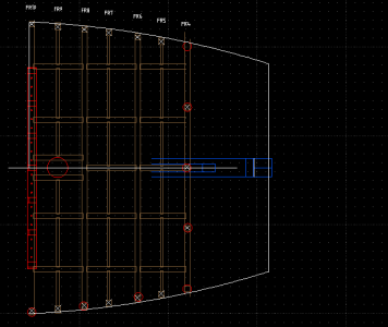
I present to you the first published pages of the Pirate Ship document.

Here is a basic tracing. It matters not what the actual measurements are, but all the proportions are correct from the image, so you just have to figure that out either on paper or in CAD and see what it comes up to. More on this later. Thanks for listening.

bow4.png
 
I think the era depicted was probably the mid to late 1700's. (1750-1800).
Hi UV
Yes, there were pirates and then privateers before, during and after your dates. Heck there are pirates today, just take a cruise off the coast of Somalia :) . That said, considering you are showing what looks like a galleon built in the 16th or 17th century and what historians refer to as the Golden Age of Piracy ended with the death of the Edward Teach in 1718 and Bartholomew Roberts in 1722 I do not think 1750-1780 makes sense. Movie ships are not necessarily the best source of information, especially when there is contemporary information to be found including the wreck of Teach's ship, La Concorde (Queen Anne's Revenge) in North Carolina. There are now drawings of her based on the wreck that you might find interesting.

Allan
 
UVSaturated, nice to meet you.
What an amazing blueprint!!:eek:
If only I'd had this blueprint when I built my Black Pearl model from scratch—how happy I would have been!!ROTF

BP09-06-27-005.jpg
 
UV, I just came across your log - what a great project! I will be watching with interest.

Congratulations on your sobriety! One day at a time.

Have you tried FreeCAD for your 3D models?
 
UV, I just came across your log - what a great project! I will be watching with interest.

Congratulations on your sobriety! One day at a time.

Have you tried FreeCAD for your 3D models?
I have. Maybe now I will have the patience to learn of it. Solid modelling was all new to me in the GUI, and I was only used to the autocad work environment, but perhaps now I can spend the time in study to figure out all the bells and whistles it has and not spend the money on commercial software. Thanks for reminding me, I had forgotten about that one!
 
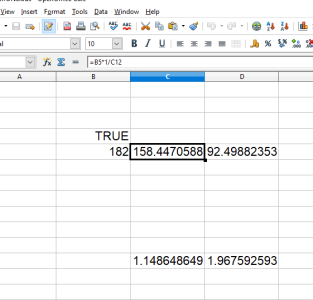
Okay, another day another dollar. I took the tracing of the picture and I found an isometric geometry that I could measure in CAD. From the picture I get these units of length; 425, 270, and 216. Instead of writing out the math on paper I just threw the ratios in a spreadsheet so it would tell me all the relations of distances according to the 425/270/216 ratio on the picture.
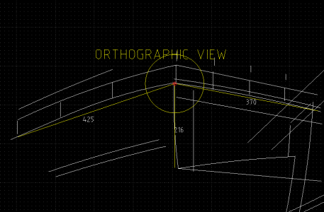
1.png
So I spewed the info into the spreadsheet to get my new numbers for the proportions of what I drew wrong:2.png
 
So roughly I ended up with the new proportions being 182/158/92. The white lines denote the perimeter of the new deck which should make the proportions better. In the end we shall see. When it is all said and done, I will probably make a foam model of the hull for $hit$ and giggles. just so I can approve of the final design. This also makes for a good 92" in reality extending the deck, which means I must also extend the keel and bow forth as well. Hopefully it will look correct from a side view, but this aint happening yet until I settle on the framework front to back. I will really get excited when I place the cannon ports on the sides and install the elbows

3.png
 
Back
Top