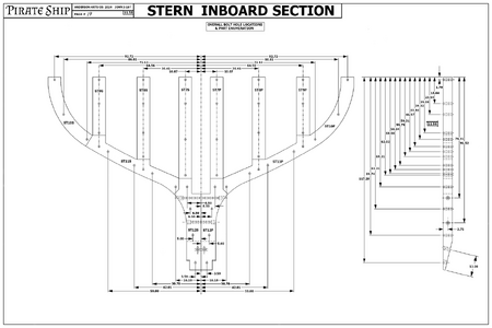
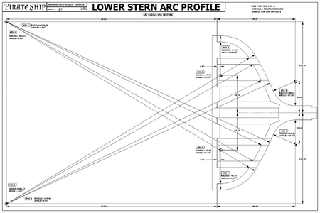
I present to you the first published pages of the Pirate Ship document.

You should be able to just click on the image, save to your desktop, and then print it out. I've done a quick test, and the results printed out on my laser on 8.5x11 inch (letter size sheet) stock was very clear and legible. You could also take the .png files on a USB stick to a local print shop and have them print them out for you on larger sheets if you needed that.
It is drawn to be printed at 24 x 36 inches.
 
Some cannon pics I found
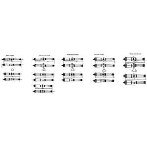
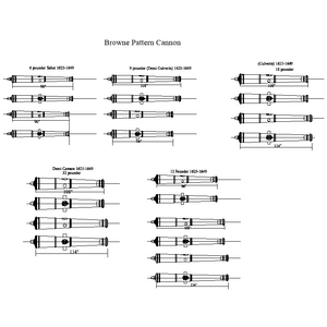
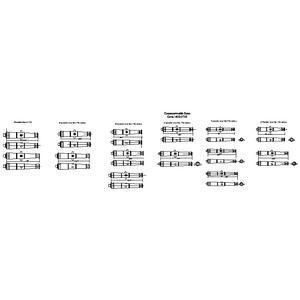
As your pirate ship looks to be from the 17th century, you may want your cannon to be from that era as well. If English, Pitt or Brown pattern guns (1625-1649) or Commonwealth pattern guns (1650-1710) may be closer to what was actually used compared to the pictures in post 18.
Allan
Cannon-Pitt-04.jpg
Pitt pattern.PNG
Cannon-Browne-04.jpg
Browne Pattern 1625 to 1649.PNG
Commonwealth Pattern.PNG

I have these in 3D as well if you want to have any of these cannon 3D printed.
Allan
 
As your pirate ship looks to be from the 17th century, you may want your cannon to be from that era as well. If English, Pitt or Brown pattern guns (1625-1649) or Commonwealth pattern guns (1650-1710) may be closer to what was actually used compared to the pictures in post 18.
Allan
View attachment 465092
View attachment 465093
View attachment 465095
View attachment 465096
View attachment 465094

I have these in 3D as well if you want to have any of these cannon 3D printed.
Allan
Thats very nice sir. Have you ever researched casting iron or bronze?
 
My idea, with the help of our Lord above, is that this document will also detail DIY how to's about casting bronze, electroplating, machining also. I am fairly knowledgeable in these fields of study. For example, if you want to buy a 1/2-13 bolt made of stainless steel for a watercraft, you will pay a very high price for the item. However, if you have a lathe, or and undersized die, you can take a standard 1/2-13 bolt, then electroplate it with stainless steel and have a much cheaper product that will do the same job, and be resiliant to oxidation from sea water.
 
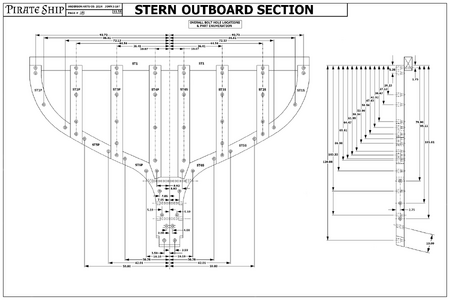
I am pleased to say, that I am delighted to produce more pages of the Pirate Ship soon. I was going to begin drawing fasteners, but Jesus told me not to. So I began drawing the ass of the ship. The Stern section. It is grouped into three sections. The lower Stern, which fastens the rudder. The ceiling of the stern above the rudder (and I have not found a name that they call that area), and the Poop deck or Castle. The names of these parts of these old ship go by various different names. Maybe someone can enlighten me about the rear of the sailing ship. I got tired of researching. Anyway, soon I will publish more pages, but these are not final drawings, so just sit on them, because in the design process, I go back and change things on previous drawings as I go on, if that makes sense.
 
WOW ANOTHER WINNER MI HAVE 2 Q2UESTIONS RIGHT NOW FIRST OF ALL I AM A COMPUTER ILLETERATE BUT CAN NAVIGATE IT ARE THE DRAWINGS THAT ARE READY CAN I DOWNLOAD THEM TO BE PRINTED AND IF I MAY ADSK WILL YOU BE ABLE TO GIVE AN EXPLANATION TO THEM. YES IN JESUESW NAME GOD BLESS STAY SAFE YOU AND YOURS DON
 
WOW ANOTHER WINNER MI HAVE 2 Q2UESTIONS RIGHT NOW FIRST OF ALL I AM A COMPUTER ILLETERATE BUT CAN NAVIGATE IT ARE THE DRAWINGS THAT ARE READY CAN I DOWNLOAD THEM TO BE PRINTED AND IF I MAY ADSK WILL YOU BE ABLE TO GIVE AN EXPLANATION TO THEM. YES IN JESUESW NAME GOD BLESS STAY SAFE YOU AND YOURS DON
Yes, yes, and yes. The drawings are for sale to other people who have more money than brains. But, the drawings here, are freely given. If you are using a cell phone, these images will probably not be usefull to you. I would encourage you to get a PC, or a laptop with a monitor that is large enough to see the drawings. As for explanations, I am totally open to explanations of any of the drawings I publish here.
 
IF YOU ARE ON A COMPUTER WITH A MOUSE, YOU CAN RIGHT CLICK YOUR MOUSE, THEN SAVE THE IMAGE TO YOUR COMPUTER. SAVE IT TO HARD DRIVE OR A USB THUMB DRIVE AND YOU CAN TAKE THEM TO A FEDEX STORE AND HAVE THEM PRINTED ON PAPER AT 24X36 BLACK AND WHITE
 
Have you ever researched casting iron or bronze?
Hi UVSaturated
The only metal I have cast into cannon is pewter. Casting bronze could be interesting but I will probably stay with making a master with a lathe then making a mold and casting in resin rather than bronze or having 3D printed guns from my collection of drawings for various eras and nationalities.

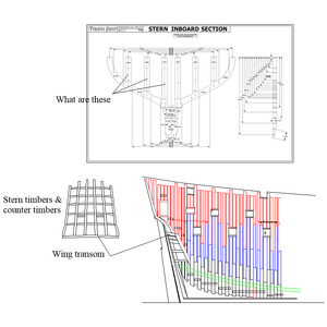
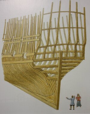
Your drawings are very interesting but I hope you don't mind me asking why you are not making the designs as they were actually done on a ship. I am not sure where your drawing below is located in a profile view so it is hard to picture the actual structure. The other two sketches I have added are a framing disposition and the stern timbers of a 17th century English ship. These sketch may make more sense than my text. The last picture is from Richard Endsor's book The Master Shipwright's Secrets. If you do not already have it I think you would find this book helpful for your project. Contemporary contracts give scantlings that you may also find helpful. :)
Allan
Pirate ship stern.PNG
1723852623582.jpeg
 
THANK YOU VERY MUCH.. ARE ALL OF THEM READY OR JUST SOME. GOD BLOESS STAYN SAFE YOU AND YOURS DON
Like I have stated before. The page numbers that are hand written are drawings that may be edited as I work on the design. You cannot trust them. Mainly it is dealing with the bolt holes and fasteners and does not have a whole lot to do with modelling it with the outside dimensions. The dimensions given are 1:1 scale so whatever scale you decide to work on, just divide the numbers which are in inches by the factor of scale. For example, if a dimension says it is 20 inches, then just divide that number on your calculator by the scale. In 1:72 scale, just divide the dimension by the scale and you will get the exact dimension scaled down. 20 inches would become .27777......20/72.
 
Hi UVSaturated
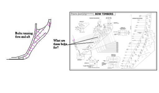
I noticed a lot of bolts running athwartships in the knee of the head in your drawings. What are these for? Looking at drawings in Goodwin's The Construction and Fitting of English Ships of War which are based on Sutherland there are no bolts like this. Is there a reason for these? He does show the bolts running fore and aft which hold the pieces of the knee of the head together which makes sense, but I cannot figure out why there are athwartship bolts. See below.
Thanks for your help.
Allan
Pirate ship knee of the head 111.PNG
 
Hi UVSaturated
I noticed a lot of bolts running athwartships in the knee of the head in your drawings. What are these for? Looking at drawings in Goodwin's The Construction and Fitting of English Ships of War which are based on Sutherland there are no bolts like this. Is there a reason for these? He does show the bolts running fore and aft which hold the pieces of the knee of the head together which makes sense, but I cannot figure out why there are athwartship bolts. See below.
Thanks for your help.
Allan
View attachment 465235
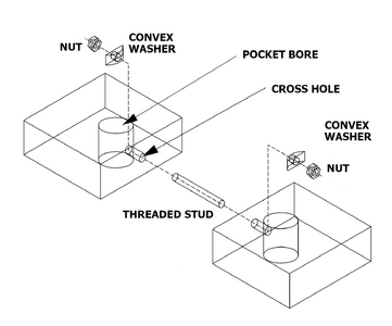
That is because I am foremost designing this ship as a full scale set of plans, for a do-it-yourselfer to build in their fair time. For the hobbyists, you can omit the bolts and just use the dimensions for the pieces and glue them together. The bolt holes you are referring to are pocket bolts, which were not invented way back then, but are a mondern connector that is used today. I will present an illustration shortly to show you this attachment method.
 
Last edited:
Hi UVSaturated
The only metal I have cast into cannon is pewter. Casting bronze could be interesting but I will probably stay with making a master with a lathe then making a mold and casting in resin rather than bronze or having 3D printed guns from my collection of drawings for various eras and nationalities.

Your drawings are very interesting but I hope you don't mind me asking why you are not making the designs as they were actually done on a ship. I am not sure where your drawing below is located in a profile view so it is hard to picture the actual structure. The other two sketches I have added are a framing disposition and the stern timbers of a 17th century English ship. These sketch may make more sense than my text. The last picture is from Richard Endsor's book The Master Shipwright's Secrets. If you do not already have it I think you would find this book helpful for your project. Contemporary contracts give scantlings that you may also find helpful. :)
Allan
View attachment 465180
View attachment 465181
It's because I am drawing all of these prints up in 2D CAD, then exporting them to illustration software. The intention is for a shipwright to craft a full sized vessel. If you wish to scale this down to a proportional sized ship, all you have to do is take the 1:1 dimensions and divide it by the scale you are using. It's like I am building a pirate ship on paper, and maybe someone will actually build a full scale ship to these drawings. You are free to use them as you will. The bolts are not intended to be period authentic to an old ship. It's like I am taking an old way and using modern conventions in construction. I hope this answers your questions.

On the drawing you ask what are 'these'. Those are vertical timbers. That piece is page 18 and 19. Those two illustrations go together and laminated with tar and are bolted together like a sandwich. The center portion, I have not drawn yet, as it it holds the rudder, and keel. What you call the 'wing transom' is already drawn on my computer, but not published yet. These pieces are the backbone of the entire ship you see. The view is of 18 & 19 are a perpundicular view of that section of the ship. It is mainly intended for those who are skilled at woodworking to know how to shape, drill, and plane the pieces of wood in it's construction. I hope this helps your inquery sir!
 
As a retired machine designer I can appreciate the work you are putting in these drawings Well done
Thank you so much. Not many people appreciate the skills I have. I confess that everything that I am I owe to God above.
 
Hi UVSaturated
I noticed a lot of bolts running athwartships in the knee of the head in your drawings. What are these for? Looking at drawings in Goodwin's The Construction and Fitting of English Ships of War which are based on Sutherland there are no bolts like this. Is there a reason for these? He does show the bolts running fore and aft which hold the pieces of the knee of the head together which makes sense, but I cannot figure out why there are athwartship bolts. See below.
Thanks for your help.
Allan
View attachment 465235
I spent more consideration on the bolts you presented in your drawing compared to mine. As I have said before, the drawings I am publishing here have two purposes. First is for anyone to build a scale model of this ship and likewise someone with more money than brains to actually manufacture these pieces of wood at full scale. The bolts you show are from the era when they did not have industrial machinery. Blacksmiths made long bolts. Frankly, I have not researched how a blacksmith would produce a long bronze rod 6-10 feet long. The reason I changed the concept of attaching the pieces together is because of a few factors. Foremost is economics. Wood is fairly reasonable at cost. However, the cost to purchase fasteners or manufacture them yourself is related to the weight, complexity, and material of the fastener. Modern watercraft utilize bronze and stainless steel hardware. What they do not know is that stainless steel is relativaly cheaper than bronze per weight. So with this in mind, I devised a system of fasteners that is way lest cost to a person building this ship. You can manufacture everything out of mild steel undersized by .030 thousandths of an inch. Then you electroplate it with stainless steel and you have a bolt that has .03 thickness of stainless steel that is corrosion resistant, and a fraction of the cost of manufacturing a solid bolt or nut made of stainless steel. Another aspect is the old way of doing things. I really don't think that too many people will purchase a drill or boring shaft 60+ inches long to run long studs through the bow. It's more cost effective for the builder to bore short holes less than 12" than a long drill miles long. Besides, a drill that long will run out and waver. If the cutting edge is not precise it will wander and come out the back of the timber way out of tolerance.
 
Thanks for explaining pocket bolts UVsaturated. What are they connecting? The knee of the head pieces, even at full scale, do not have to be laminated so I cannot figure out their purpose. Sorry for the questions, but this project is intriguing, and I want to understand as much as possible.

What are the vertical pieces in the stern section? I thought they might be the stern timbers, but stern timbers always sat on the wing transom, not on a frame.

Thanks for your help in explaining things.Thumbsup

Allan

pocket bolt.png
 
Thanks for explaining pocket bolts UVsaturated. What are they connecting? The knee of the head pieces, even at full scale, do not have to be laminated so I cannot figure out their purpose. Sorry for the questions, but this project is intriguing, and I want to understand as much as possible.

What are the vertical pieces in the stern section? I thought they might be the stern timbers, but stern timbers always sat on the wing transom, not on a frame.

Thanks for your help in explaining things.Thumbsup

Allan
The reason for two sections sandwiched together is it is probably easier to buy planks of wood that are 6"thick and plane them down to 5.5" than a 12" plank and plane it down to 11" Thicker timbers are more costly, unless you are going to harvest your own wood and have it sent to a saw mill then kiln dried.
 
Back
Top