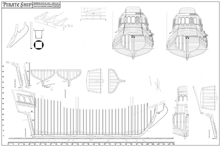
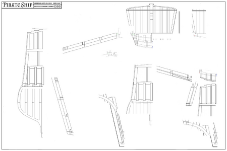
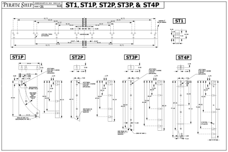
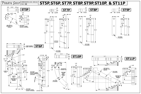
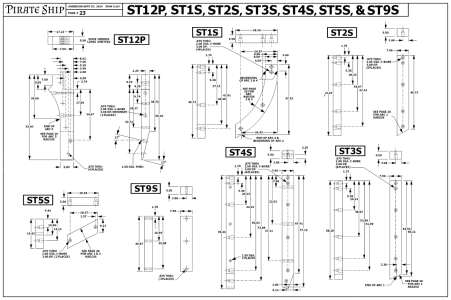
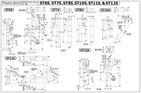
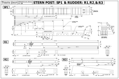
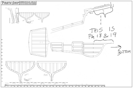
I present to you the first published pages of the Pirate Ship document.

Thanks for explaining pocket bolts UVsaturated. What are they connecting? The knee of the head pieces, even at full scale, do not have to be laminated so I cannot figure out their purpose. Sorry for the questions, but this project is intriguing, and I want to understand as much as possible.

What are the vertical pieces in the stern section? I thought they might be the stern timbers, but stern timbers always sat on the wing transom, not on a frame.

Thanks for your help in explaining things.Thumbsup

Allan

PIRATESHIP4.png
 
UVSaturated Your concepts are very interesting and thanks again for sharing your work, it is appreciated.:) I totally get the idea of saving money on wood and using stainless steel instead of iron or wooden treenails on a full size ship.

Are you a naval architect? I am so used to the centuries old tried and true designs and scantlings from, Deane, Sutherland, Murray/(Monceau), Steel, that any unproven designs for a full size 17th or 18th century sailing ship would be very scary to me. Then again most, if not all, of us here are modelers so using the classic designs of the masters might make more sense.

Regardless, your drafting skills are top notch and your ideas are interesting to study. I imagine you would have had some great conversations with those old designers if we could do a little time travel!

Allan
I wear a lot of hats Allan. My first bona-fide career was an apprenticeship in CNC Machining through the State Of Ohio. I worked at a plastic injection mold shop in Dayton, Ohio. That is where I cut my teeth on machining. So, no I am not a Naval Architect (that kinda sounds scary). Later in life I spent some time in a woodworking shop that made high end furniture and cabinetry. Needless to say, if you are skilled at machining steel, then woodworking is very easy. The only big difference is the way the material is worked, and shrinkage. Steel does not change in size too much unless it is heated to hundreds or thousands of degrees. Wood, though expands and contract with the moisture content so you have to take that into consideration.
 
180 pages??? That is a lot of drawings and probably very detailed as well. Looking forward to the rest of your posts.
Marcus
 
Any other pages on here that have handwritten page numbers are obsolete. This is the final draft of the Pirate Ship document and will be a work in progress. For builders, all the dimensions are in inches and at full scale. Therfore if you wish to build this ship at any scale take the dimension and divide it by the scale you wish to use. For example, the overall length of the ship at 1:1 scale is around 122 feet, which is 1464 inches. Divide the inch dimension to a scale you desire. 1:2 would yield around 61 feet, about the length of a tractor and trailer. 1:4 yields around 30 feet long. If you want it to fit on your coffee table, I would suggest 1:36 or 1:72. These will yield a model length of 40 inches and 20 inches respectively. The bolt hole dimensions are for someone who wishes to build the full scale vessel. You may or may not choose that much detail, and assemble the pieces together or create the keel, and bow out of one piece of material. This is up to the builder. Again, any images I have released earlier will be incorrect. Some of the hole dimensions did not add up correctly when I was checking errors, and I revised them. I will continue this project. The next section will be about fasteners used on the full scale ship, so it may not be relevent to the model builder. After that small section I will return with the Stern, Rudder, Aft Castle, and the frames. Enjoy, and I thank all of you for sharing your hobby with me.
Hallo @UVSaturated
we wish you all the BEST and a HAPPY BIRTHDAY
Birthday-Cake
 
THANK YOU VERY MUCH.. ARE ALL OF THEM READY OR JUST SOME. GOD BLOESS STAYN SAFE YOU AND YOURS DON
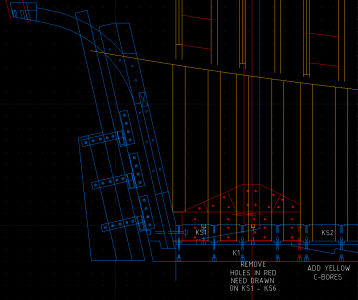
I put a new statement om the first page. Basically its a work in progress and I cannot guarantee that all the images are complete. The older they are or numerically lower the page is, the more likely it is set in stone, but I am finding that as I progress, I need to make one change that affects something else in the drawings. I began in earnest drawing these by hand as illustrations, then when I got to designing the bow components I started noticing errors in some of my drawings that affected other things, that would exponentionally create endless design changes if left unchecked, so I check my work many times over. Then I realized that some of the curves and compund angles are going to be difficult to figure out mathematically for someone cutting the wood on a table saw or bandsaw so I then switched to 2D CAD to draw up the pieces and elements which makes it much quicker to makes changes on the fly and change bunches of things quckly. When the CAD model looks good, then I use it as a reference to draw the components in an illustration software, because my CAD cannot render good quality images. Take care buddy.
 
Back
Top