
-

SUBSCRIBE TO SHIPS IN SCALE TODAY!
The beloved Ships in Scale Magazine is back and charting a new course for 2026!
Discover new skills, new techniques, and new inspirations in every issue.
NOTE THAT OUR NEXT ISSUE WILL BE July/August 2026 -

Win a Free Custom Engraved Brass Coin!!!
As a way to introduce our brass coins to the community, we will raffle off a free coin during the month of August. Follow link ABOVE for instructions for entering.


You are using an out of date browser. It may not display this or other websites correctly.
You should upgrade or use an alternative browser.
You should upgrade or use an alternative browser.
IJN Pre-Dreadnought Battleship Mikasa by Merit 1:200 with Pontos and KA Models


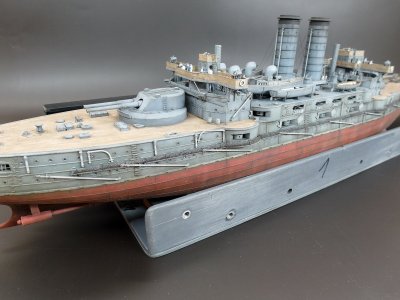
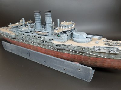
Ahoy, fellow modelers.
Lately, I’ve rarely made it to my workbench, as I’ve been occupied with other things.
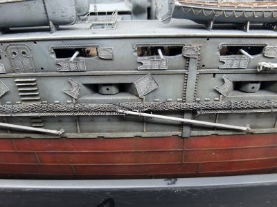
But with my vacation coming up, I took the opportunity this weekend to at least secure the starboard spars.
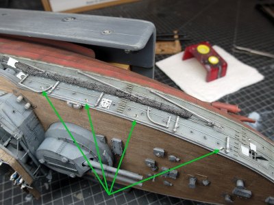
To do this, I once again cut up some railing stanchions and repurposed them as line tensioners.
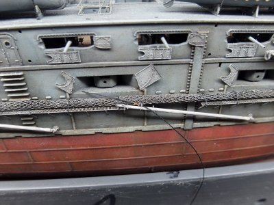
Led through the eye on the spar and secured behind the net, just as I saw on the SMS Goeben.
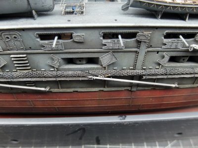
Painted and weathered.
The same towards the bow.
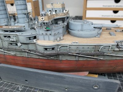
That concludes the spars on this side.
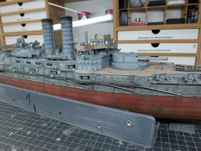
The three missing lids for the midships gun ports have been fitted.
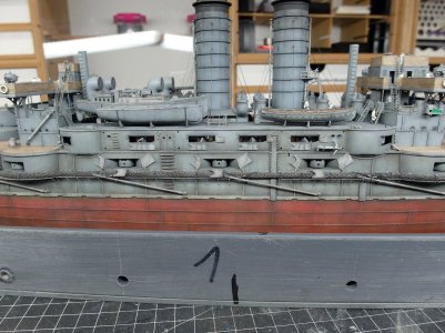
And one more picture of the starboard side before heading off on vacation.️
Lately, I’ve rarely made it to my workbench, as I’ve been occupied with other things.
But with my vacation coming up, I took the opportunity this weekend to at least secure the starboard spars.
To do this, I once again cut up some railing stanchions and repurposed them as line tensioners.
Led through the eye on the spar and secured behind the net, just as I saw on the SMS Goeben.
Painted and weathered.
The same towards the bow.
That concludes the spars on this side.
The three missing lids for the midships gun ports have been fitted.
And one more picture of the starboard side before heading off on vacation.️


You are a master of small details, Joelle!
Thanks for the positive feedback Jim, i really appreciate it. 
I just love creating all those little details myself. Of course, that’s also why building such a seemingly mundane plastic model usually takes me well over two years.
I just love creating all those little details myself. Of course, that’s also why building such a seemingly mundane plastic model usually takes me well over two years.
Hello fellow modelers.
I’m back from vacation.
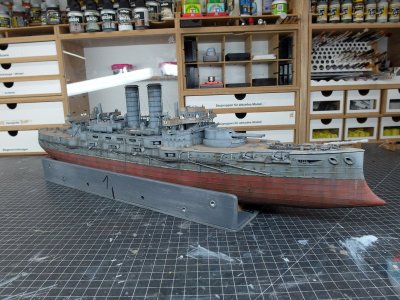
To ease back into things, I’m picking up right where I left off. I am finishing up the port-side torpedo net shelf and its associated spars.
As a result, there aren’t too many new photos today.
Once again, I fashioned cable tensioners from the shortened railing stanchions and attached them to the individual spars.
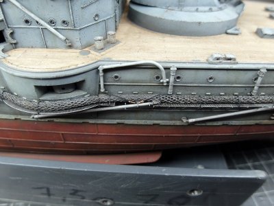
And so, without further ado, I present to you the result of my efforts.
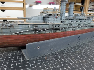
This phase of construction was actually a bit nerve-wracking, due to the somewhat bumpy road leading up to it.
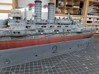
But this way, I can now wrap this up and attend to the remaining details. There are still plenty of them left.
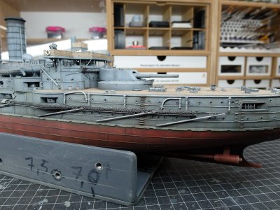
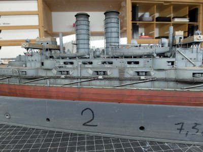
Last but not least, here is a picture of the three midships gun port lids, which are now also hanging on the port side of the casemates.
I’m back from vacation.
To ease back into things, I’m picking up right where I left off. I am finishing up the port-side torpedo net shelf and its associated spars.
As a result, there aren’t too many new photos today.
Once again, I fashioned cable tensioners from the shortened railing stanchions and attached them to the individual spars.
And so, without further ado, I present to you the result of my efforts.
This phase of construction was actually a bit nerve-wracking, due to the somewhat bumpy road leading up to it.
But this way, I can now wrap this up and attend to the remaining details. There are still plenty of them left.
Last but not least, here is a picture of the three midships gun port lids, which are now also hanging on the port side of the casemates.
Ahoy everyone.
To get back into the swing of things after my vacation, I’m starting with a small detail that was still missing:
The “crown” for the funnels.
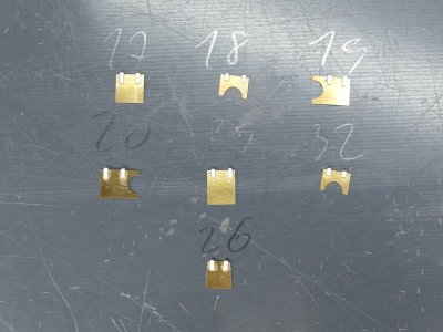
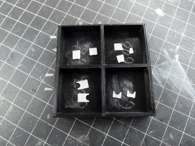
First, I cut out all the individual parts for the funnel grating.
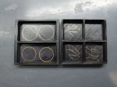
Once again, a very delicate piece of work.
You have to be extremely careful when sanding down the connection points where the tabs held the part in the sheet.
Assembly is easier after that. I used four small strips to ensure the ring lay flat while I glued the struts in place.
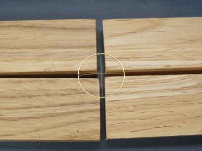
And slap it right onto the funnel.
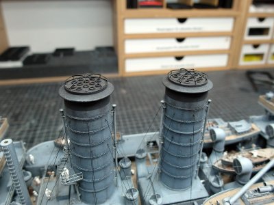
Here is another question for the maritime experts among you.
I had always assumed that those frameworks were for canvas covers designed to form a funnel shroud and protect the boiler from rain.
However, even in port, the boiler was rarely allowed to go out completely, as the ships had to constantly generate steam for the electrical generators (lighting, radio, pumps) and to maintain operational readiness. Consequently, a framework with a canvas cover would have burned up or been ruined by soot.
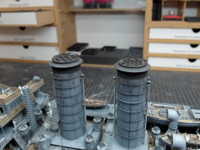
So, here is my question:
Are these perhaps splinter-protection grilles rather than supports for tarpaulins? Did they serve to prevent enemy shell fragments, debris, or masts collapsing during combat from falling into the boiler rooms?
Or were they makeshift frameworks that simply remained in place throughout the ship’s active service, ready to support the tarpaulins used during periods of complete decommissioning—such as a months-long stay in the shipyard or during cold winter lay-ups?
To get back into the swing of things after my vacation, I’m starting with a small detail that was still missing:
The “crown” for the funnels.
First, I cut out all the individual parts for the funnel grating.
Once again, a very delicate piece of work.
You have to be extremely careful when sanding down the connection points where the tabs held the part in the sheet.
Assembly is easier after that. I used four small strips to ensure the ring lay flat while I glued the struts in place.
And slap it right onto the funnel.
Here is another question for the maritime experts among you.
I had always assumed that those frameworks were for canvas covers designed to form a funnel shroud and protect the boiler from rain.
However, even in port, the boiler was rarely allowed to go out completely, as the ships had to constantly generate steam for the electrical generators (lighting, radio, pumps) and to maintain operational readiness. Consequently, a framework with a canvas cover would have burned up or been ruined by soot.
So, here is my question:
Are these perhaps splinter-protection grilles rather than supports for tarpaulins? Did they serve to prevent enemy shell fragments, debris, or masts collapsing during combat from falling into the boiler rooms?
Or were they makeshift frameworks that simply remained in place throughout the ship’s active service, ready to support the tarpaulins used during periods of complete decommissioning—such as a months-long stay in the shipyard or during cold winter lay-ups?
That is the great question, and it has been debated by naval historians and modelers for years, IMHO. Based on what is known from available photographs, shipyard drawings, and naval practice, I believe your reasoning is sound. The framework was primarily intended to support funnel covers (weather awnings or tarpaulins), not as splinter protection. However, those covers were not normally fitted while the boilers were in operation.Ahoy everyone.
To get back into the swing of things after my vacation, I’m starting with a small detail that was still missing:
The “crown” for the funnels.
First, I cut out all the individual parts for the funnel grating.
View attachment 623389
Once again, a very delicate piece of work.
You have to be extremely careful when sanding down the connection points where the tabs held the part in the sheet.
Assembly is easier after that. I used four small strips to ensure the ring lay flat while I glued the struts in place.
View attachment 623390
And slap it right onto the funnel.
View attachment 623391
Here is another question for the maritime experts among you.
I had always assumed that those frameworks were for canvas covers designed to form a funnel shroud and protect the boiler from rain.
However, even in port, the boiler was rarely allowed to go out completely, as the ships had to constantly generate steam for the electrical generators (lighting, radio, pumps) and to maintain operational readiness. Consequently, a framework with a canvas cover would have burned up or been ruined by soot.
View attachment 623392
So, here is my question:
Are these perhaps splinter-protection grilles rather than supports for tarpaulins? Did they serve to prevent enemy shell fragments, debris, or masts collapsing during combat from falling into the boiler rooms?
Or were they makeshift frameworks that simply remained in place throughout the ship’s active service, ready to support the tarpaulins used during periods of complete decommissioning—such as a months-long stay in the shipyard or during cold winter lay-ups?
- Even when moored, warships usually maintained steam for auxiliary machinery, electrical generators, pumps, and to reduce the time needed to get underway.
- A canvas cover over an active funnel would quickly be scorched, covered in soot, or even catch fire if fitted too closely.
- Contemporary photographs almost invariably show the framework in place, but the canvas itself absent during normal service.
- The framework was generally too light to stop shell splinters or heavy debris.
- Splinter protection over uptakes would have required a much stronger structure, which would also have interfered with the free flow of exhaust gases.
- I have never seen a naval manual or shipyard drawing describing these structures as protective grilles.
- During prolonged refits when all boilers were shut down.
- During reserve or laid-up status.
- While fitting out or awaiting commissioning.
- Possibly in tropical anchorages when a boiler was completely cold, and weather protection was desirable. In those circumstances, the canvas would keep rain, leaves, birds, and debris out of the uptake and reduce corrosion inside the funnel.
As a fellow ship modeler, I find this question especially interesting because many kit manufacturers and even some instruction sheets label these as "funnel covers," which can be misleading. The framework was usually a permanent fitting, whereas the canvas cover was a temporary accessory used only under specific conditions. That distinction is often overlooked.
Wow, thank you very much for that extremely instructive and informative explanation, Jim.
That explains it perfectly.
You are right, when 'commissioned' the boilers of ships (and of locomotives for that matter) were kept hot, because a boiler has to be heated rather slowly to avoid cracks, particularly at the joints of steam- and smoke-pipes. However, when decommissioned, the fires were cleaned out. Also, during peace-time not all boilers were necessarily running, just the ones providing the steam for the necessary services. Boilers require periodic cleaning to remain effective. During those times the funnels would have been also covered. I learned this from a user on another forum.
So, thanks again for that excellent explanation.
That explains it perfectly.
You are right, when 'commissioned' the boilers of ships (and of locomotives for that matter) were kept hot, because a boiler has to be heated rather slowly to avoid cracks, particularly at the joints of steam- and smoke-pipes. However, when decommissioned, the fires were cleaned out. Also, during peace-time not all boilers were necessarily running, just the ones providing the steam for the necessary services. Boilers require periodic cleaning to remain effective. During those times the funnels would have been also covered. I learned this from a user on another forum.
So, thanks again for that excellent explanation.
Moving on to the details that seem never-ending.
Everything has been cut out and prepared for that.
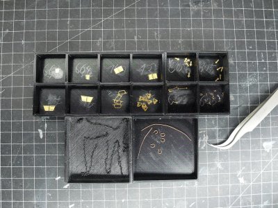
To start things off and get into the swing of things, I attached the missing covers to the bow gun.
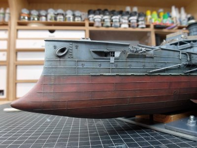
All missing fittings and the single anchor chain on the port side have been installed.
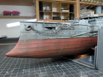
No big deal.
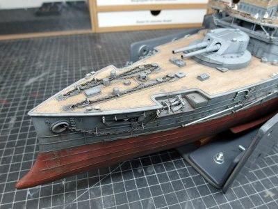
I also installed two additional chain supports on the starboard side.
Although none of my assembly instructions call for this, I looked at photos of various ships of the line; on those, the chain for the spare anchor definitely rests on a support and doesn’t sag significantly.
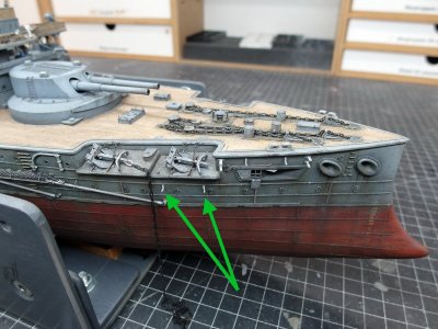
And so, the chains for both anchors have been laid out on this side, resulting in quite a tangle.
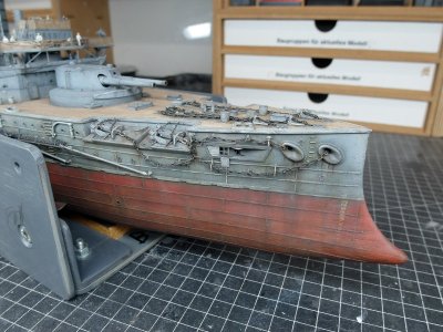
I’m quite pleased with the result, though, and it brings me a little bit further along on the bow.
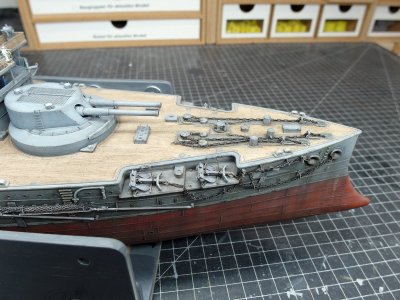
Everything has been cut out and prepared for that.
To start things off and get into the swing of things, I attached the missing covers to the bow gun.
All missing fittings and the single anchor chain on the port side have been installed.
No big deal.
I also installed two additional chain supports on the starboard side.
Although none of my assembly instructions call for this, I looked at photos of various ships of the line; on those, the chain for the spare anchor definitely rests on a support and doesn’t sag significantly.
And so, the chains for both anchors have been laid out on this side, resulting in quite a tangle.
I’m quite pleased with the result, though, and it brings me a little bit further along on the bow.

Just modeling perfection...No big deal.
The next details are on the agenda.
Once again, countless individual parts were removed from the circuit boards and deburred.
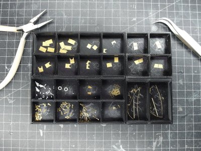
As at the bow, additional fittings are attached along the hull.
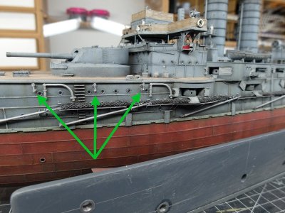
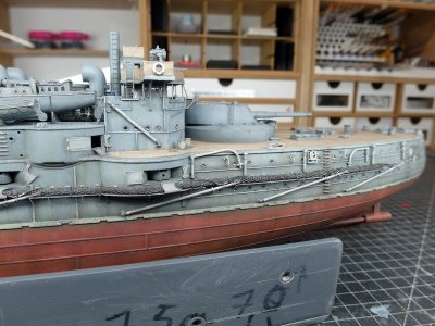
The round casemates have now also received their covers.
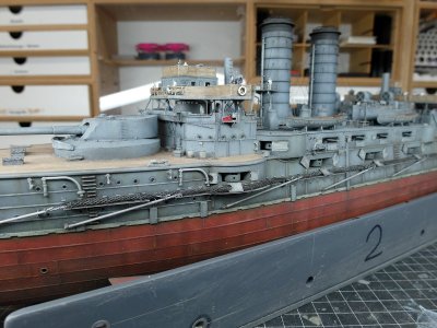
For the upper casemate, I decided to depict one half closed—just for a bit of variety.
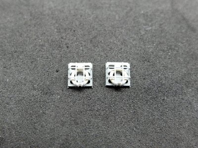
Here is another little work of art from Pontos: the lifebuoy release cage facing the stern.
And quickly attached.
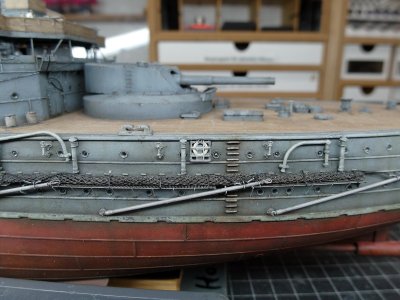
Last but not least, the lid for the stern gun. With this, the final gun port lid on the port side is installed.
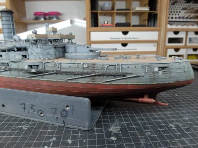
You’ve probably guessed it already: the same thing again to starboard.
Once again, countless individual parts were removed from the circuit boards and deburred.
As at the bow, additional fittings are attached along the hull.
The round casemates have now also received their covers.
For the upper casemate, I decided to depict one half closed—just for a bit of variety.
Here is another little work of art from Pontos: the lifebuoy release cage facing the stern.
And quickly attached.
Last but not least, the lid for the stern gun. With this, the final gun port lid on the port side is installed.
You’ve probably guessed it already: the same thing again to starboard.


Moving on to the fittings on the starboard side.
I am simulating the final hinges on the gun port lids.
Done—the last covers are painted and ready to be attached.
The model was laid on its side again to let gravity assist with the gluing process.
That makes positioning the small fittings so much easier. You can align them properly and let the adhesive cure, since they simply stay in place on the hull.
I actually only paint these tiny parts once they’ve already been attached to the hull. It’s simply easier that way.
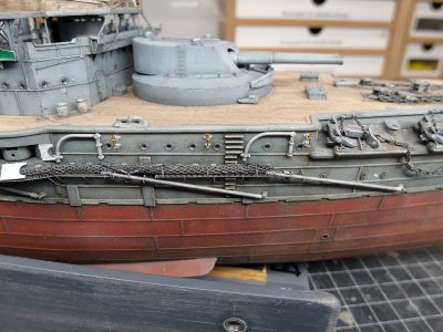
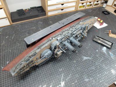
Everything is fully weathered, and with that, I’ve put this rather dry stage of the build behind me.
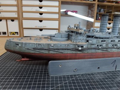
Finally, all the covers on the casemates are in position.
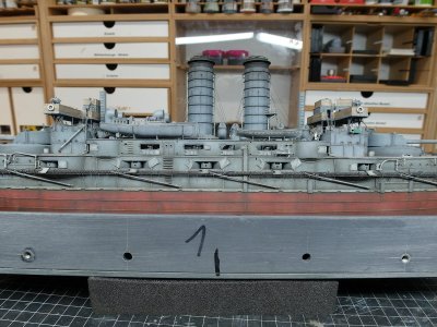
Now, work continues at the very stern with the last two spars and the gallery.
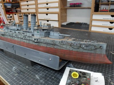
I am simulating the final hinges on the gun port lids.
Done—the last covers are painted and ready to be attached.
The model was laid on its side again to let gravity assist with the gluing process.
That makes positioning the small fittings so much easier. You can align them properly and let the adhesive cure, since they simply stay in place on the hull.
I actually only paint these tiny parts once they’ve already been attached to the hull. It’s simply easier that way.
Everything is fully weathered, and with that, I’ve put this rather dry stage of the build behind me.
Finally, all the covers on the casemates are in position.
Now, work continues at the very stern with the last two spars and the gallery.
Here is a quick mini-build update for you.
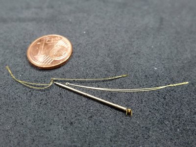
I’ve attached the last two spars at the stern, and the following image clearly illustrates why I’m glad I managed to pull this off without any mishaps.
The delicate photo-etched ropes had to be twisted 90 degrees at the eyelet so they would hang from the spar at the correct angle.
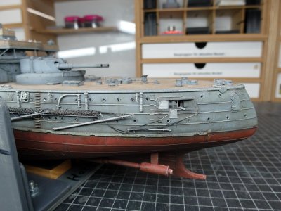
And so, without further ado, I present the result to you.
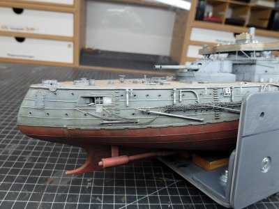
Now that I’ve managed that, I can finally get around to attaching the last major component to the exterior of the hull.
The gallery.
I’ve attached the last two spars at the stern, and the following image clearly illustrates why I’m glad I managed to pull this off without any mishaps.
The delicate photo-etched ropes had to be twisted 90 degrees at the eyelet so they would hang from the spar at the correct angle.
And so, without further ado, I present the result to you.
Now that I’ve managed that, I can finally get around to attaching the last major component to the exterior of the hull.
The gallery.
Let’s move on to attaching the final—and rather tricky—component to the hull.
As always, let’s start with the key players for the upcoming assembly steps.
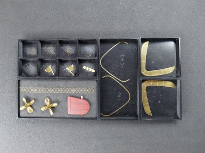
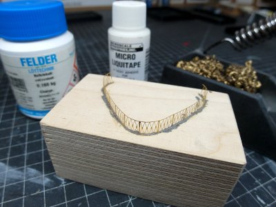
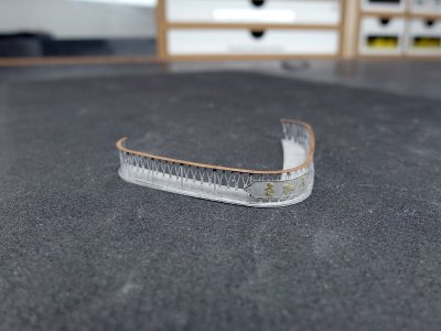
After cleaning the very delicate components, I decided to solder the railing to the upper handrail. To do this, I secured the upper section to a block of wood using a little Micro Liquitape and carefully soldered the railing into the groove, piece by piece.
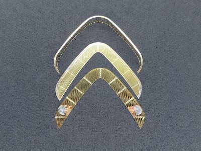
The second groove was then attached to the gratings, and the two round mounts were also secured with solder.
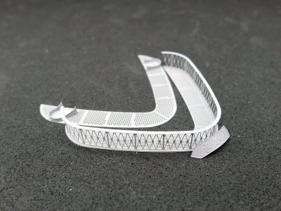
Assembled, and then everything was given a coat of primer.
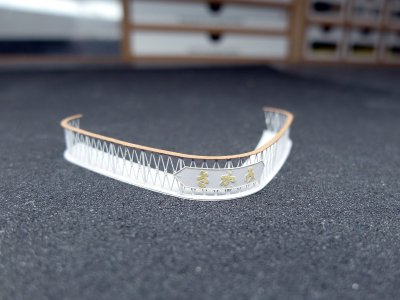
Afterwards, I used my finest sandpaper to sand the paint off the nameplate down to the brass and attached the plaque to the railing. I double-checked the original photos of the Mikasa to make sure I was mounting it the right way up—that could have been quite embarrassing otherwise.
Then everything weathered again.
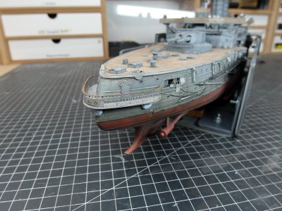
Tacked the gallery to the hull with Blu-Tack to align it properly.
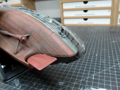
After that, I secured everything properly with acrylic adhesive and attached the struts and the stern anchor. The rudder has also been fitted into its mounts. However, I’ll leave the propulsion system for later.
And with that, the gallery is hanging in its place.
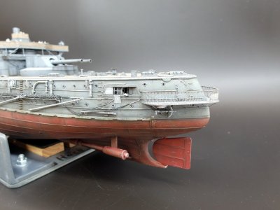
I am very glad that everything worked out well, given that I had made quite a few changes to the hull—such as all the profiles—so I was really worried that something might not fit. But as you can see, it is hanging straight and at the intended height on the stern, exactly where it belongs.
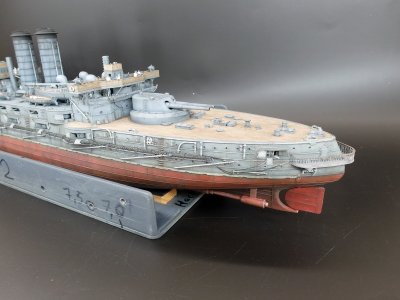
I initially considered replicating the small release mechanism on the stern anchors as well, but ultimately decided against it. I’d like to get this model finished soon, and I’ve already scratch-built plenty of details. That should suffice; otherwise, I’ll start losing interest.
So, I can report that the final components on the outer hull can be considered complete.
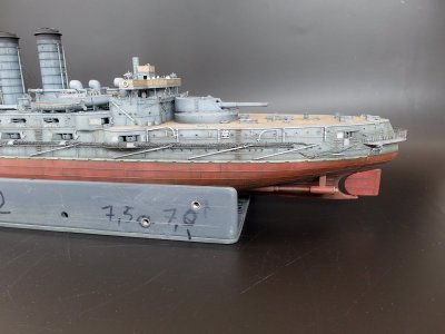
Moving on to the masts.
As always, let’s start with the key players for the upcoming assembly steps.
After cleaning the very delicate components, I decided to solder the railing to the upper handrail. To do this, I secured the upper section to a block of wood using a little Micro Liquitape and carefully soldered the railing into the groove, piece by piece.
The second groove was then attached to the gratings, and the two round mounts were also secured with solder.
Assembled, and then everything was given a coat of primer.
Afterwards, I used my finest sandpaper to sand the paint off the nameplate down to the brass and attached the plaque to the railing. I double-checked the original photos of the Mikasa to make sure I was mounting it the right way up—that could have been quite embarrassing otherwise.
Then everything weathered again.
Tacked the gallery to the hull with Blu-Tack to align it properly.
After that, I secured everything properly with acrylic adhesive and attached the struts and the stern anchor. The rudder has also been fitted into its mounts. However, I’ll leave the propulsion system for later.
And with that, the gallery is hanging in its place.
I am very glad that everything worked out well, given that I had made quite a few changes to the hull—such as all the profiles—so I was really worried that something might not fit. But as you can see, it is hanging straight and at the intended height on the stern, exactly where it belongs.
I initially considered replicating the small release mechanism on the stern anchors as well, but ultimately decided against it. I’d like to get this model finished soon, and I’ve already scratch-built plenty of details. That should suffice; otherwise, I’ll start losing interest.
So, I can report that the final components on the outer hull can be considered complete.
Moving on to the masts.
Magnificent modeling!


Hello Madtatt,
it may be a bit late and off topic for your build, but due to your picture of non-rangefinders at the very beginning
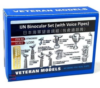
it reminds me that in some forum several years ago there was an unfinished discussion if Zeiss/Jena delivered modern rangefinders to the IJN before Tshishima in 1903/04. These May be responsible for the fore better aiming results of the Japanese fleet. In this time Japanese officials kept this information strictly classified and Zeiss Said, their documents were stolen in 1945 and still in alliied hands.
Did you met anything about this topic or you know anything about this rumors?
Thanks a lot, Chris
it may be a bit late and off topic for your build, but due to your picture of non-rangefinders at the very beginning
it reminds me that in some forum several years ago there was an unfinished discussion if Zeiss/Jena delivered modern rangefinders to the IJN before Tshishima in 1903/04. These May be responsible for the fore better aiming results of the Japanese fleet. In this time Japanese officials kept this information strictly classified and Zeiss Said, their documents were stolen in 1945 and still in alliied hands.
Did you met anything about this topic or you know anything about this rumors?
Thanks a lot, Chris
Last edited: