• SUBSCRIBE TO SHIPS IN SCALE TODAY!

    The beloved Ships in Scale Magazine is back and charting a new course for 2026!
    Discover new skills, new techniques, and new inspirations in every issue.

    NOTE THAT OUR NEXT ISSUE WILL BE July/August 2026
  • Win a Free Custom Engraved Brass Coin!!!
    As a way to introduce our brass coins to the community, we will raffle off a free coin during the month of August. Follow link ABOVE for instructions for entering.

Integration of 3D Modeling and Printing of plastic details into Wooden Ship Model Construction (HMS Victory | Cutter Alert) by Serikoff

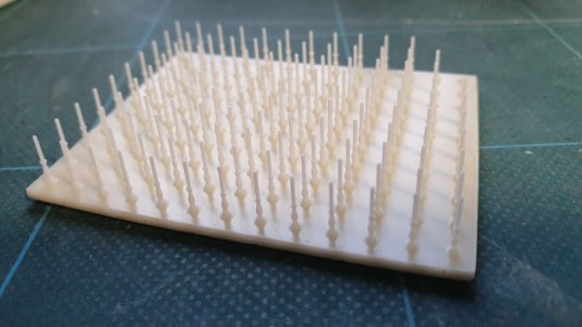
I think they would print ok with a decent resin printer.
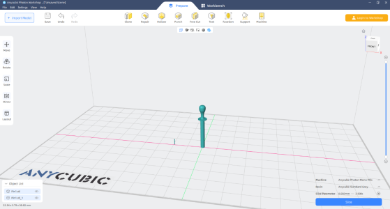
So, this morning, I drew a belaying pin in Fusion 360 totally freehand, not to any spec. Just eyeballed it. I can add accuracy and detail later. I then created and STL file of the pin and took it into my 3D Slicer. (Anycubic Workshop). I scaled the pin to 30mm and then scaled another down to 4mm and put them side by side. They would print. Maybe after I try doing a couple of different replicas of pins and scaled them to a few different sizes, I might try printing some and see what happens. I would choose a resin that is tough and can create detail - most likely Craftsman DLP resin (it has an amount of ceramic in it too). There are other resins that would provide flexibility and toughness too.2025-02-12 (8).png
 
So, this morning, I drew a belaying pin in Fusion 360 totally freehand, not to any spec. Just eyeballed it. I can add accuracy and detail later. I then created and STL file of the pin and took it into my 3D Slicer. (Anycubic Workshop). I scaled the pin to 30mm and then scaled another down to 4mm and put them side by side. They would print. Maybe after I try doing a couple of different replicas of pins and scaled them to a few different sizes, I might try printing some and see what happens. I would choose a resin that is tough and can create detail - most likely Craftsman DLP resin (it has an amount of ceramic in it too). There are other resins that would provide flexibility and toughness too.View attachment 500928
I wonder how many you can print at the same time? That would be something to look at, I think.
 
Until I win a lottery I’ve given up on that. I bought a budget handheld model last year but sold it on within a few months. Nowhere near sophisticated enough for our game. I imagine pro-quality gear does a better job but suspect you would still need to put in many hours converting the scan if dimensional accuracy mattered (which it did for me).
I need to sit down and see what I can do with it. Right now it`s in a box collecting dust...
 
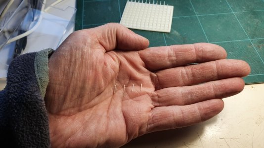
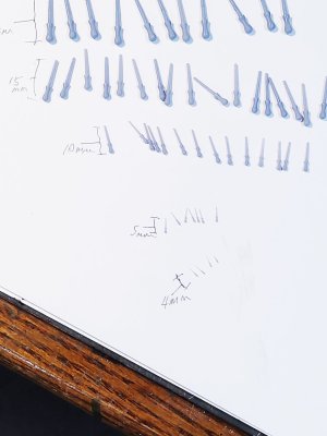
So I redrew a pin then printed a few. I took a few pictures with my SLR camera and will work on those tomorrow. But I grabber a couple of pics with this Galaxy tablet. Show here. I started with 25mm, then down to 20, 15, 10 5 and even 4mm. In keeping with scale tge 4 and 5mm pins are very small and the pins themselves, to scale are about as thick as a human hair. I do't know how you would ever wrap rigging around such a tiny pin. These pics do not show the smallest pins - I'll show them here tomorrow.20250213_192815.jpg20250213_192905.jpg
 
When I printed them, the problem was not in the printing itself, but in the fact that if the thickness of the part is 0.1-0.2 mm, it can deform and bend during the final processing (while raw) and break (after exposure), so you need to intentionally slightly increase some parts for reinforcement and for banal visualization, since very small details will not be visible on the model.
I wanted to come back to this. Parts can shrink and deform both during printing and post-processing. In my experience, most of the shrinkage occurs during printing and, if dimensional accuracy is critical, you need to play with the xyz scale settings in your slicer once you know, from a test print, what's happening. Be aware that shrinkage is not necessarily uniform, it depends on factors such as the object shape and design, orientation on the print plate, nature and extent of supports, even resin temperature, so you may need to make different adjustments for each axis. And of course this can have you chasing your tail.

I have found that it is best to process thin section prints immediately after the print sequence has completed. Leaving ultra-thin things to sit on the plate for a couple of hours, perhaps as a way of letting the wet resin drain off, can lead to distortion. Even the breeze from the printer fan can cause thin sections of wet resin to deform.

Parts can also deform during cleanup. I do my IPA wash sequence while the parts are still attached to the plate. Small parts are bound to get damaged if they are rattling around in the cage. It also cleans up the plate for later use.

I mix resins to try to get the properties I most need for a part. Typically, I mix standard resin with ABS-like to get more rigidity but still with enough flex. I find standard resin is usually too brittle and elegoo ABS is too bendy, but a blend gives a nice result. Ultra-fine parts are always going to be very fragile though. For window bars or lattices, adding 'glass' can help.
 
I wanted to come back to this. Parts can shrink and deform both during printing and post-processing. In my experience, most of the shrinkage occurs during printing and, if dimensional accuracy is critical, you need to play with the xyz scale settings in your slicer once you know, from a test print, what's happening. Be aware that shrinkage is not necessarily uniform, it depends on factors such as the object shape and design, orientation on the print plate, nature and extent of supports, even resin temperature, so you may need to make different adjustments for each axis. And of course this can have you chasing your tail.

I have found that it is best to process thin section prints immediately after the print sequence has completed. Leaving ultra-thin things to sit on the plate for a couple of hours, perhaps as a way of letting the wet resin drain off, can lead to distortion. Even the breeze from the printer fan can cause thin sections of wet resin to deform.

Parts can also deform during cleanup. I do my IPA wash sequence while the parts are still attached to the plate. Small parts are bound to get damaged if they are rattling around in the cage. It also cleans up the plate for later use.

I mix resins to try to get the properties I most need for a part. Typically, I mix standard resin with ABS-like to get more rigidity but still with enough flex. I find standard resin is usually too brittle and elegoo ABS is too bendy, but a blend gives a nice result. Ultra-fine parts are always going to be very fragile though. For window bars or lattices, adding 'glass' can help.
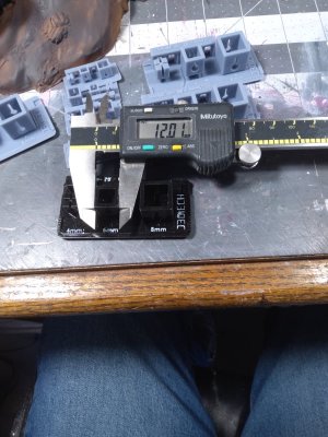
I find that calibration for each resin helps. These boxes were printed at 2X and as you can see, they're dimensionally stable. They have been washed and cured.

20240612_101940.jpg
So I redrew a pin then printed a few. I took a few pictures with my SLR camera and will work on those tomorrow. But I grabber a couple of pics with this Galaxy tablet. Show here. I started with 25mm, then down to 20, 15, 10 5 and even 4mm. In keeping with scale tge 4 and 5mm pins are very small and the pins themselves, to scale are about as thick as a human hair. I do't know how you would ever wrap rigging around such a tiny pin. These pics do not show the smallest

So I redrew a pin then printed a few. I took a few pictures with my SLR camera and will work on those tomorrow. But I grabber a couple of pics with this Galaxy tablet. Show here. I started with 25mm, then down to 20, 15, 10 5 and even 4mm. In keeping with scale tge 4 and 5mm pins are very small and the pins themselves, to scale are about as thick as a human hair. I do't know how you would ever wrap rigging around such a tiny pin. These pics do not show the smallest pins - I'll show them here tomorrow.View attachment 501155View attachment 501156
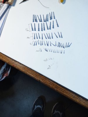
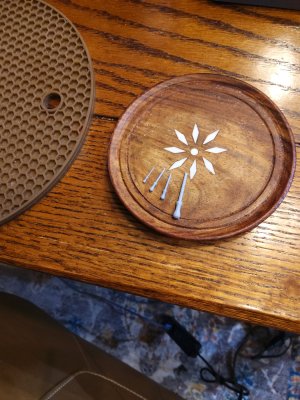
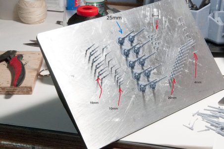
Printed a few in different sizes. size was adjusted in my slicer by changing the scale. The slicer allows me to change scale while maintaining proportionality in all 3 axis if I so choose. I printed 25, 20, 15, 10 5, and 4mm's. One picture shows the belaying pins as printed on the build plate, the other pictures removed from the plate and photographed. Note: while I did print at least 10 each, not many of the 4mm and 5mm pins survived the scraping off the build plate. I can change the exposure times to make them more robust (rigid) but this run is only a test to see what happens. I think that when needed to print the very small sizes (5mm or less) it might be better to print the entire pin rail with pins installed as one piece. And I cannot imagine needed to actually rig to the smaller pins on a model while using the smallest pins to actually secure the ropes. Let me know what you think.Belay-Pins-A.jpgBelay-Pins-B.jpgPinsPlate-1edited.JPG
 
Last edited:
I wanted to come back to this. Parts can shrink and deform both during printing and post-processing. In my experience, most of the shrinkage occurs during printing and, if dimensional accuracy is critical, you need to play with the xyz scale settings in your slicer once you know, from a test print, what's happening. Be aware that shrinkage is not necessarily uniform, it depends on factors such as the object shape and design, orientation on the print plate, nature and extent of supports, even resin temperature, so you may need to make different adjustments for each axis. And of course this can have you chasing your tail.

I have found that it is best to process thin section prints immediately after the print sequence has completed. Leaving ultra-thin things to sit on the plate for a couple of hours, perhaps as a way of letting the wet resin drain off, can lead to distortion. Even the breeze from the printer fan can cause thin sections of wet resin to deform.

Parts can also deform during cleanup. I do my IPA wash sequence while the parts are still attached to the plate. Small parts are bound to get damaged if they are rattling around in the cage. It also cleans up the plate for later use.

I mix resins to try to get the properties I most need for a part. Typically, I mix standard resin with ABS-like to get more rigidity but still with enough flex. I find standard resin is usually too brittle and elegoo ABS is too bendy, but a blend gives a nice result. Ultra-fine parts are always going to be very fragile though. For window bars or lattices, adding 'glass' can help.
Thanks for the advice. I already figured it all out through trial and error, but thanks anyway.
 
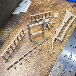
In this post, I'd like to share the results of 3D modeling metal parts for the Alert 1777 cutter model.

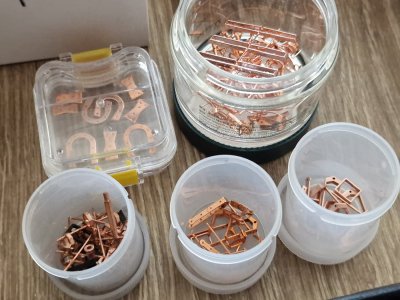
All these parts will be 3D printed and copper-plated, followed by a blackening.

I discuss galvanization (copper coating of plastic) in more detail here >>>.

I'll cover the modeling, printing, and preparation in more detail in the next post.

The modeling results, in three parts, are available at the links below: Part 1/3


3D 02.jpg
3D 09.jpg

3D 12.jpg
3D 06.jpg


Part 2/3


3D 22.jpg
3D 28.jpg

3D 40.jpg
3D 36.jpg


Part 3/3


3D 50.jpg
3D 55.jpg
 
Now a few words about 3D printing.

After modeling, we have STL files that need to be prepared in the Anycubic printing slicer.

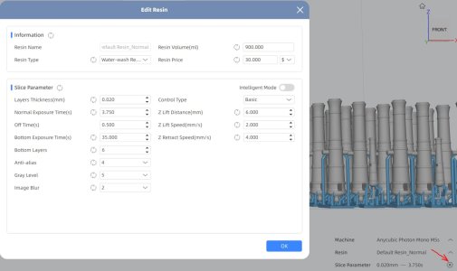
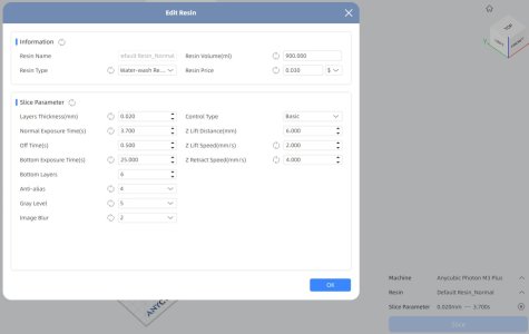
The slicer parameters (Anycubic Photon Workshop) are as follows:

Slice.JPG

I print on an Anycubic Photon M3 Plus 3D printer with a 20-micron layer thickness. I initially used Anycubic Water-Wash Resin, but I switched to the new Anycubic Water-Wash Resin 2.0 HD gray. It's convenient because it doesn't require alcohol removal; regular water is fine.

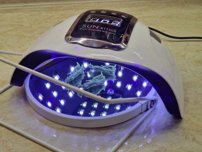
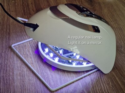
However, curing with UV light is essential, and a regular manicure lamp will do the trick.

Alert 838.jpg

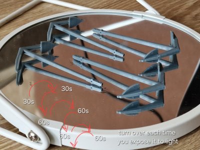
I use a mirror for even illumination.

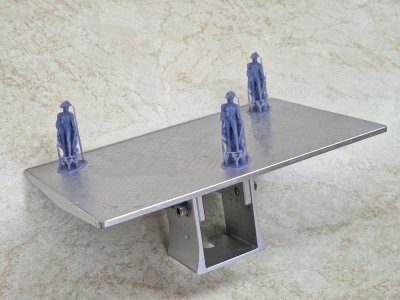
Remember, printing time directly depends on the height of the item you're printing...

Alert 836.jpg

Alert 837.jpg

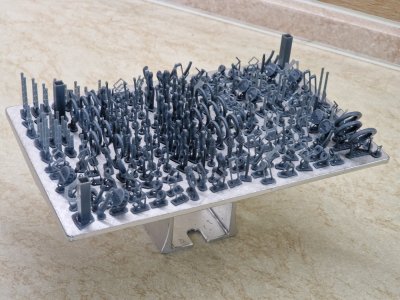
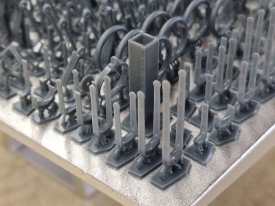
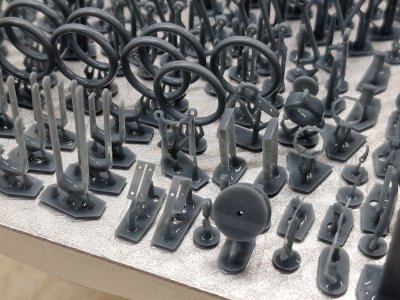
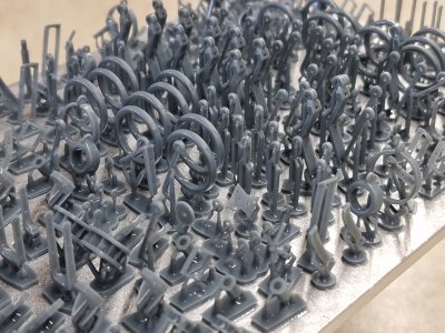
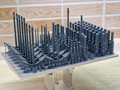
...so it doesn't matter how much space is filled on the table—the key is the height! So, if you need a lot of copies, print them all at once—it'll be faster.

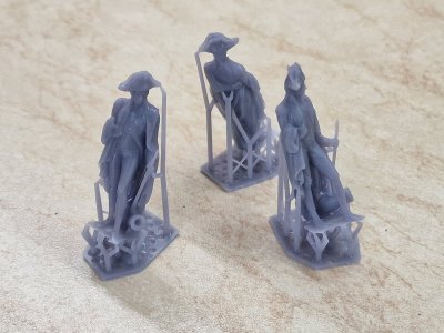
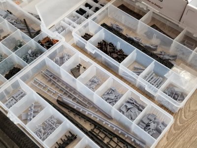
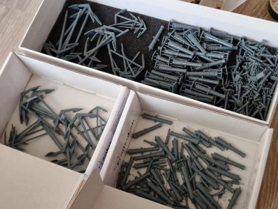
20260504_174726.jpg

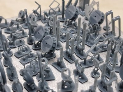
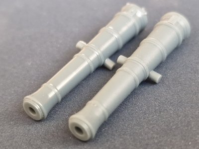
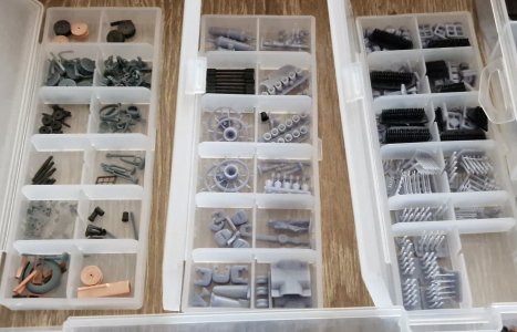
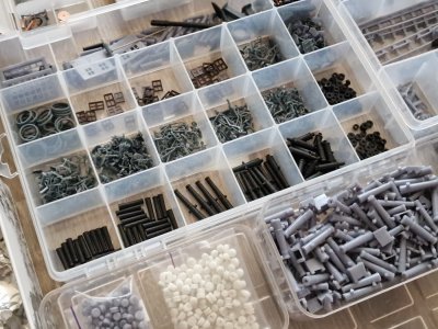
As you can see, there are almost five copies of almost every part on the table, except for the cannons and anchors. These are for my two models and one other, plus spares for possible defects during printing or post-processing. (By the way, not a single part was defective during printing.)

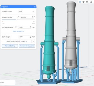
An important point is to install the supports correctly. There are some basic rules, but you can find them online, and you'll only understand the nuances with practice.

The huge advantage is that, firstly, you can print an infinite number of the required parts, which is very difficult to do individually by hand. The parts will be absolutely identical. More importantly, the thickness of the parts can be as small as 0.2-0.3 mm. The important thing is that such parts must first be separated from their holders while still wet and exposed between two pieces of glass (or by other means) to fix their shape so that they don't deform during exposure. By the way, it is better to remove the supports (holders) before curing and when they are wet - this reduces the risk of plastic tearing off the part.

20260504_174733.jpg

20260504_174750.jpg

20260504_174754.jpg

20260504_174811.jpg

Now all these parts are waiting to be copper plated and blackened...

My tests with copper coating of plastic and subsequent blackening are here >>>.
 
I am very happy to find this thread.
I want to learn more.
I have built a few Dutch VOC ships over the years.
When I started work on the Batavia I knew about 3D printing and although it looked interesting I did not see a use for me.
I have been a mechanical engineer all my life and use AutoCAD and Solid Works regularly.
I decided to give it a try and found it very rewarding that I can use it for my hobby.
I just started with an inexpensive printer but found out how easy it is to design a part, draw it and then print it.

I am still a beginner but I am using some of the parts I created on my build now. I don't use it that much yet but see more potential and enjoy the process of designing my own part and using it on the build.

20250905_103931.jpg
 
This will be of interest to both beginners (those just starting out or considering buying a printer) and experienced users who might learn something new from it.

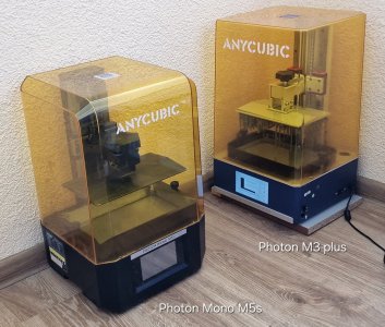
I currently have two printers:

Alert 2614.jpg

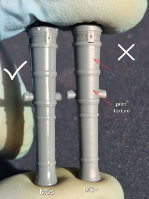
The M3+ with a 6MP sensor and FEP film, and the M5s with 12MP and ACF film.

These are two completely different devices, each with its own pros and cons. I'll share my experience using them, but this isn't a manual or a recommendation. It's merely an experience and a starting point for those who are completely new to this topic or who can't set up the perfect print.

I previously attached a screenshot of the M3+ settings, and with these settings, I printed small parts perfectly (shown above). When I got a second printer (the M5), I decided to print the same set on it, but I adjusted the settings for it, considering that it was supposedly much better. BUT! Several prints were unsuccessful. The base would fall off, or parts would break away from the supports... And I realized that they can write a lot of things on paper, but in the end I came to my proven settings and practically duplicated them for the second printer (although it is considered better, these settings were completely suitable for both the M5 and M3+).

Alert 2615 M5.JPG

Through trial and error, I realized I needed to disable Intelligent Mode in the M5. Otherwise, the printer takes control and typically sets parameters that might fail for extremely small details, resulting in defects. I was beginning to think this printer was bad, or that it had run 666 print cycles with a total of 293,318 layers (to put that in perspective, 4,000 layers can take 15 hours to print). I even replaced the film in the vat, but that didn't help. Until I changed the settings like on my old printer and increased the support.

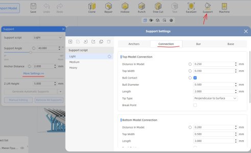
Alert 2616 М5 под.JPG

In the support section, you can leave everything at default except three parameters: 0.250/0.350 and the checkbox next to the 0.500 diameter ball. Through trial and error, I found that these exact parameters on two printers provide the minimum support without the risk of tearing. If you try them, start with these values and increase them if tearing occurs.

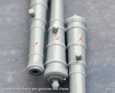
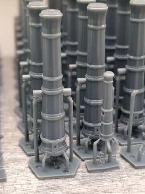
So, the old M3 printer printed small parts perfectly, but when printing cannons and anchors (the print took 13.5 hours), there were defects.

Alert 2616.jpg

Alert 2617.jpg

I'm not sure what it was, most likely the film, but there weren't that many of these grooves. Considering I usually print much more than necessary, it's tolerable...

Alert 2618.jpg

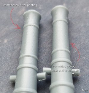
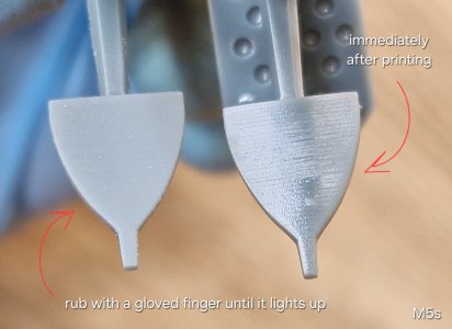
But the fact that the print texture was visible on the surface is a drawback. There's a way to combat this. After thoroughly rinsing in the shower (and remember, I use a resin that's water-washable, not alcohol-based) and after drying, but BEFORE curing with a UV lamp, rub the surface with a gloved finger. This will reduce the print mark significantly.

Alert 2619.jpg

But then you must definitely expose the plastic to ultraviolet light!

Alert 2620.jpg

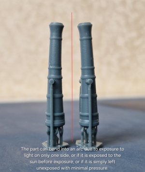
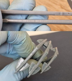
A regular nail lamp will do the trick. However, you need to apply light evenly to each side, alternating the two. If you only apply light to one side, or if you don't apply light and let the piece sit in the sun or just pile up with light pressure, it will bend into an arch.

Alert 2621.jpg

Therefore, the parts must be exposed to the light invertedly, first with a 30-second exposure and then with a one-minute exposure several times. Unexposed parts are fragile and can scratch and damage each other simply by friction.

Alert 2622.jpg

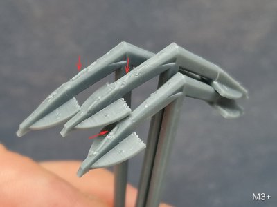
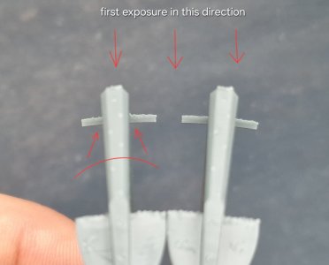
Some parts, like anchors, have flat areas and to prevent them from twisting, they need to be exposed first on the side opposite to the twisting.

Alert 2623.jpg

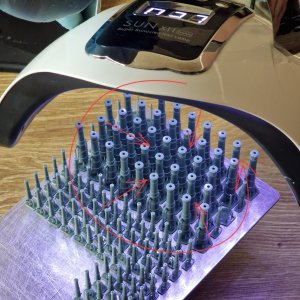
Check the situation. Sometimes it's better to break off the holders and expose the parts to light on the mirror, but sometimes you need to expose them without removing the holders. In these cases, you need to expose them constantly, changing the angle of the light and rotating either the lamp or the table.

Alert 2624.jpg

In this situation, I handled things differently. I tore the anchors from their supports and rubbed the surface to remove the print marks.

Alert 2625.jpg

The print is more visible on flat surfaces, but that's not a problem since I'll be polishing the surfaces before the copper coating. To reduce the workload, it's better to rub before the surface is exposed, and the surface will be much smoother.

The entire bottom section is covered in marks from the holders, but when removed, there's no defect because I chose holders with a ball. This area will also be sanded on flat surfaces, making it convenient and quick.

Alert 2626.jpg

It's recommended to position long, straight parts at a 45-degree angle. This reduces print height and time, but I don't like it that way. In this case, many of the holders will be on the side of the part, which means extra work and sanding. Most importantly, when tilted, long parts inevitably bend. And then it's very difficult to straighten them. While this can be resolved with an anchor at the copper plating stage (simply physically bending them back), it's not possible with a cannon. Therefore, I position everything strictly vertically.

Alert 2627.jpg

Alert 2628.jpg

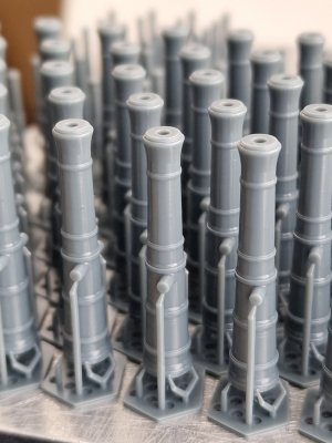
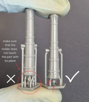
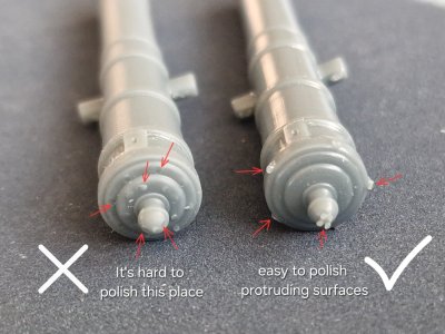
And in this case, I also replaced the supports. I had to completely reprint all the guns, because the first time (on the M3), I installed too many of them in a very bad location, where polishing them would be very difficult. But this time (on the M5), I placed them completely differently, and here's my logic.

Alert 2629.JPG

First, I reduced their height (which will speed up printing). Second, I removed all the supports from the complex back surface, moving them to the side, where they're very easy to sand. And to make sure they're at the very bottom, I installed four supports at the tip of the gun, which will then be easily sanded to a spherical shape. I also reduced the number of supports on top.

Alert 2630.jpg

And now, after the breakaway of supports...

Alert 2631.jpg

...the sanding area is convenient and there's no torn-out "meat" from the supports (which is a defect), as the support with a ball was chosen. These balls remain on the surface and can be sanded off.

And the most important difference between the two printers is the texture of complex (non-flat) surfaces.

Alert 2632.jpg

The key here is to leave the sticky layer undisturbed and to cure the parts directly on the stage without lifting them from the supports. Apply the UV light in a circular motion to ensure all surfaces are evenly exposed and to achieve a smooth, gliding (non-sticky) surface.

Alert 2633.jpg

As you can see, the result on the left is much better than the one on the right. (Just ignore the dust... it will be removed before applying the graphite varnish.)

Alert 2634.jpg

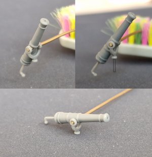
Preliminary fitting (for dimensions, use 1mm wire). Next comes grinding, polishing, and copper plating with a blackened finish.
 
Last edited:
Great post!!! Your results are superlative. Now if you can offer to provide all the 3D drawings I might convince myself to look at the payback versus buying them.:). My problem is that I pay less than a US$ for a 3D printed cannon barrel, including shipping. The last ones were for 1:64 scale guns. With a machine that costs over $600, I would need to build six first rates to recoup my investment and that will likely never happen.:)
Thanks again for your report and explanations, this was great to see!
Allan
 
Great post!!! Your results are superlative. Now if you can offer to provide all the 3D drawings I might convince myself to look at the payback versus buying them.:). My problem is that I pay less than a US$ for a 3D printed cannon barrel, including shipping. The last ones were for 1:64 scale guns. With a machine that costs over $600, I would need to build six first rates to recoup my investment and that will likely never happen.:)
Thanks again for your report and explanations, this was great to see!
Allan
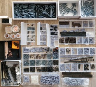
I understand. But I got both printers for free. Whenever we buy a new one at work, I keep the old one. Now I have two. And I'm saying that you can safely buy a used one and it won't be that expensive. But for copper plating, I need a lot of blanks, so having a printer is a must for me. And if you're painting the parts, then naturally buying a printer isn't always wise if you can find parts cheaply somewhere.
 
Back
Top