I love the detailing! That's a nice kit!Here are the completed chocks sitting in the mast step:
View attachment 421733
The chocks will need to be shaped when the mast is fitted, but that’s another story.
This little piece is a great example of how accurately the parts are cut. The notches in the floor riders are cut slightly off vertical so the pieces joining them angles inwards to match the chocks. And the tenons are just long enough to fit perfectly into the notches. That’s not to say that there was some work required to get it to go together, but it is a pleasing result all the same.
-

Win a Free Custom Engraved Brass Coin!!!
As a way to introduce our brass coins to the community, we will raffle off a free coin during the month of August. Follow link ABOVE for instructions for entering.
-

PRE-ORDER SHIPS IN SCALE TODAY!
The beloved Ships in Scale Magazine is back and charting a new course for 2026!
Discover new skills, new techniques, and new inspirations in every issue.
NOTE THAT OUR FIRST ISSUE WILL BE JAN/FEB 2026
You are using an out of date browser. It may not display this or other websites correctly.
You should upgrade or use an alternative browser.
You should upgrade or use an alternative browser.
La Salamandre 1752 1:48 (CAF) by Salty
- Thread starter Salty
- Start date
- Watchers 24
-
- Tags
- caf model la salamandre
Good afternoon. You have owned this. Really good modelling. Cheers GrantHere are the completed chocks sitting in the mast step:
View attachment 421733
The chocks will need to be shaped when the mast is fitted, but that’s another story.
This little piece is a great example of how accurately the parts are cut. The notches in the floor riders are cut slightly off vertical so the pieces joining them angles inwards to match the chocks. And the tenons are just long enough to fit perfectly into the notches. That’s not to say that there was some work required to get it to go together, but it is a pleasing result all the same.
- Joined
- Mar 1, 2023
- Messages
- 144
- Points
- 213

Uwek, Paul and Grant, thank you for taking the time to post. I’m not sure I would have got this far without the encouragement of the SOS members and you three in particular. It’s a lovely kit alright and I think I am probably pushing a bit harder to make sure I do her justice.
I have started work on the deck beams. They are made up of three layers with notches for the carlings:
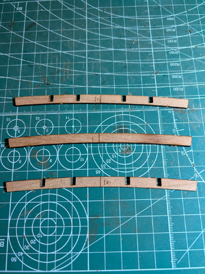
I clean out the notches, then glue the components together and then clean the rest of the laser charring off. Rather than using sandpaper, I am using a chisel to shave the charring off in the notches. This keeps everything square for the carlings.
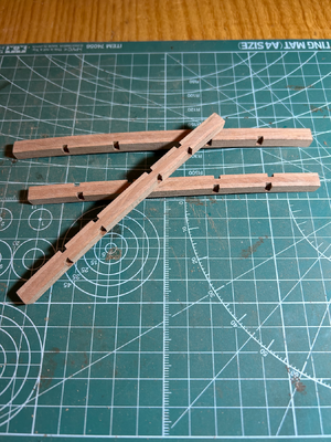
For the moment, I haven’t cleaned the front and back faces as they are numbered and this helps with the orientation - e.g. 1a faces forward and 1b faces aft.
I have started work on the deck beams. They are made up of three layers with notches for the carlings:

I clean out the notches, then glue the components together and then clean the rest of the laser charring off. Rather than using sandpaper, I am using a chisel to shave the charring off in the notches. This keeps everything square for the carlings.

For the moment, I haven’t cleaned the front and back faces as they are numbered and this helps with the orientation - e.g. 1a faces forward and 1b faces aft.
My current kit uses the same strategy on the beams (and other parts as appropriate). It's really quite a clever solution that provides for a very clean and precise notch. I'm not as enthusiastic about the resultant layered look however. How noticeable that is depends on the tone of the wood making up the layers. Your kit seems to be pretty close in tone on these beams - it should all disappear into the background.Uwek, Paul and Grant, thank you for taking the time to post. I’m not sure I would have got this far without the encouragement of the SOS members and you three in particular. It’s a lovely kit alright and I think I am probably pushing a bit harder to make sure I do her justice.
I have started work on the deck beams. They are made up of three layers with notches for the carlings:
View attachment 422344
I clean out the notches, then glue the components together and then clean the rest of the laser charring off. Rather than using sandpaper, I am using a chisel to shave the charring off in the notches. This keeps everything square for the carlings.
View attachment 422345
For the moment, I haven’t cleaned the front and back faces as they are numbered and this helps with the orientation - e.g. 1a faces forward and 1b faces aft.
Looking good
There are all pros and cons
with sandwich structure you have some color difference, but with exact location of the notches
without sandwich you have one beam, but you have to cut out the notches with a chisel - maybe not so precise
or you have cnc milled beams, than the kit is more expensive and you have the clean the rounded notches
Important now will be, that you mark the center of each beam and when you adjust the length of the beams, so that they fit into the framing, that you reduce the length on both sides - the center axis is most important (from bow to stern) -> than you will have also a correct alignment of the notches and the carlings
If the carlings are zick-zack and not correctly aligned - you will recognize it very much
This is a great posting @Uwek - one that I will be putting to use on my build (re: centerline of the beams). My thanks!Looking good
There are all pros and cons
with sandwich structure you have some color difference, but with exact location of the notches
without sandwich you have one beam, but you have to cut out the notches with a chisel - maybe not so precise
or you have cnc milled beams, than the kit is more expensive and you have the clean the rounded notches
Important now will be, that you mark the center of each beam and when you adjust the length of the beams, so that they fit into the framing, that you reduce the length on both sides - the center axis is most important (from bow to stern) -> than you will have also a correct alignment of the notches and the carlings
If the carlings are zick-zack and not correctly aligned - you will recognize it very much
- Joined
- Mar 1, 2023
- Messages
- 144
- Points
- 213

Paul, I take your point about the layered look of the beams. The components are cut from six different billets. To my eye the outer components match, but the middle piece, which is slightly thicker, seems a shade darker. Perhaps it’s the grain or glue line which draws your eye to it? The alternative - cutting 8 mortises in each of 15 beams - is a little terrifying to consider. Hopefully, there will be enough other things to distract attention to it.
Uwek, thanks for the suggestion to will mark a mid-point on each beam as they will need to line up so the carlings fit neatly. I think Paul has likened model ship building to a game of Jenga and he is right - there’s a lot of things that have to fit together and I feel I need to be thinking a couple of steps ahead most of the time.
Here are deck beams laid out as sit in order in the hull, bow on bottom and stern on top.
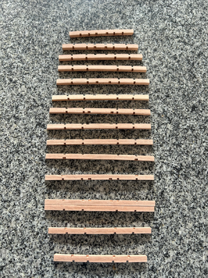
Beam 3 and 4 touch (but are at different heights).
I have been testing the beams in the hull and, as far as I can tell, everything is OK. Some adjustments will be needed to the beams in the bow and stern because of the frame bevelling, but the midship beams seem to need very little.
Uwek, thanks for the suggestion to will mark a mid-point on each beam as they will need to line up so the carlings fit neatly. I think Paul has likened model ship building to a game of Jenga and he is right - there’s a lot of things that have to fit together and I feel I need to be thinking a couple of steps ahead most of the time.
Here are deck beams laid out as sit in order in the hull, bow on bottom and stern on top.

Beam 3 and 4 touch (but are at different heights).
I have been testing the beams in the hull and, as far as I can tell, everything is OK. Some adjustments will be needed to the beams in the bow and stern because of the frame bevelling, but the midship beams seem to need very little.
To build a POF model is like playing Chess - and before fixing an element you have to think and maybe check the other elements connected.....I feel I need to be thinking a couple of steps ahead most of the time.
Think twice before you fix
I know from my own experience, that these notches are fitting very good
- Joined
- Dec 16, 2016
- Messages
- 1,178
- Points
- 493

Hi Salty, It’s coming along nicely, your work looks very professional, all neatly done. Your log is excellent, informative and detailed but you’re also making it interesting to follow. KenPaul, I take your point about the layered look of the beams. The components are cut from six different billets. To my eye the outer components match, but the middle piece, which is slightly thicker, seems a shade darker. Perhaps it’s the grain or glue line which draws your eye to it? The alternative - cutting 8 mortises in each of 15 beams - is a little terrifying to consider. Hopefully, there will be enough other things to distract attention to it.
Uwek, thanks for the suggestion to will mark a mid-point on each beam as they will need to line up so the carlings fit neatly. I think Paul has likened model ship building to a game of Jenga and he is right - there’s a lot of things that have to fit together and I feel I need to be thinking a couple of steps ahead most of the time.
Here are deck beams laid out as sit in order in the hull, bow on bottom and stern on top.
View attachment 423359
Beam 3 and 4 touch (but are at different heights).
I have been testing the beams in the hull and, as far as I can tell, everything is OK. Some adjustments will be needed to the beams in the bow and stern because of the frame bevelling, but the midship beams seem to need very little.
- Joined
- Mar 1, 2023
- Messages
- 144
- Points
- 213

Uwek, I like the chess analog. Unfortunately, my opponent is doing quite well at present…
Ken, thanks for your kind words. HMS Blandford looks absolutely wonderful. I am also following your Sopwith Camel log and have no doubt you’ll end up with another fascinating example to add to your collection.
Onto the deck clamps.
I am soaking each section for a few minutes in hot water, a quick wipe, shape with fingers and then clamped in place on the hull. The first section in place:
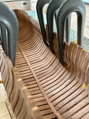
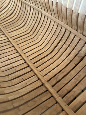
The clamps are for making musical instruments. They are made of aluminium and are quite stiff but still lightweight. I think they will be able to reach most places on the inside of the hull except for the flat section in the bilge. It took a while for them to arrive from overseas, but they were worth the wait.
Ken, thanks for your kind words. HMS Blandford looks absolutely wonderful. I am also following your Sopwith Camel log and have no doubt you’ll end up with another fascinating example to add to your collection.
Onto the deck clamps.
I am soaking each section for a few minutes in hot water, a quick wipe, shape with fingers and then clamped in place on the hull. The first section in place:


The clamps are for making musical instruments. They are made of aluminium and are quite stiff but still lightweight. I think they will be able to reach most places on the inside of the hull except for the flat section in the bilge. It took a while for them to arrive from overseas, but they were worth the wait.
The clamps are great looking and very helpful - do you have a link to a shop?
- Joined
- Mar 1, 2023
- Messages
- 144
- Points
- 213

Uwek, a link to the clamps:
https://www.dictum.com/en/clamps-jbk/aluminium-repair-clamp-jaw-depth-85-mm-705890
Dictum has lots of other tools which I have found very useful. They are a bit more expensive, but are a joy to use, particularly if you like doing things by hand.
Here are the clamps in the bow after being glued in place.
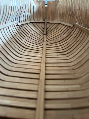
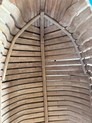
Originally, I had one length for each side, but shaping wasn’t completely successful as they needed both curve and twist. I decided to install in two pieces in the end as this helped with the twist element. I also removed some material from the lower outside edge of the clamp near the stemson to get it to sit flush against the hawse pieces.
I am reasonably happy, despite the clamp not being completely fair from frame 9 to the stemson, but it’s actually pretty level. The brest hook and the three deck beams that sit on this section of the deck clamp are all level.
https://www.dictum.com/en/clamps-jbk/aluminium-repair-clamp-jaw-depth-85-mm-705890
Dictum has lots of other tools which I have found very useful. They are a bit more expensive, but are a joy to use, particularly if you like doing things by hand.
Here are the clamps in the bow after being glued in place.


Originally, I had one length for each side, but shaping wasn’t completely successful as they needed both curve and twist. I decided to install in two pieces in the end as this helped with the twist element. I also removed some material from the lower outside edge of the clamp near the stemson to get it to sit flush against the hawse pieces.
I am reasonably happy, despite the clamp not being completely fair from frame 9 to the stemson, but it’s actually pretty level. The brest hook and the three deck beams that sit on this section of the deck clamp are all level.
Many thanks for the link to Dictum - great from germany so the postage etc. will be not so expensiveUwek, a link to the clamps:
https://www.dictum.com/en/clamps-jbk/aluminium-repair-clamp-jaw-depth-85-mm-705890
Dictum has lots of other tools which I have found very useful.
I ordered already several tools and materials from them - f.e the Superglue I am using which is only there available (in Europe)
Once more many thanks
- Joined
- Mar 1, 2023
- Messages
- 144
- Points
- 213

Uwek, I would really like to visit one of their stores to see everything in person. I guess I can keep dreaming…
Here are the clamps in the stern.
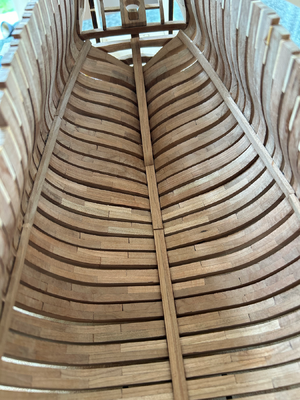
As was the case for the bow, I had one length for each side, but decided to use two to accommodate the curve and twist required.
I have tested a few more deck beams. They seem to fit (some fitting required for bevelled frames). The beams in the stern seem to be right as well as the deck will extend through to the transom at the right spot.
Here are the clamps in the stern.

As was the case for the bow, I had one length for each side, but decided to use two to accommodate the curve and twist required.
I have tested a few more deck beams. They seem to fit (some fitting required for bevelled frames). The beams in the stern seem to be right as well as the deck will extend through to the transom at the right spot.
Good afternoon. Boy if my first POF looks like this I would be ecstatic. Cheers GrantI am reasonably happy
- Joined
- Mar 1, 2023
- Messages
- 144
- Points
- 213

I must admit to initially gluing the midship sections of the clamps at the wrong height - 5 mm too high. I have no idea why I did that. I think I just forgot what side of the pencil mark to put the clamp. Thankfully I had second thoughts a few hours later after and re-measured. The sections came unglued quite nicely after I painted some water on the joints. No damage to clamps or frames. I am using fish glue but I wouldn’t like to try to loosen a join after something had been set for a week.
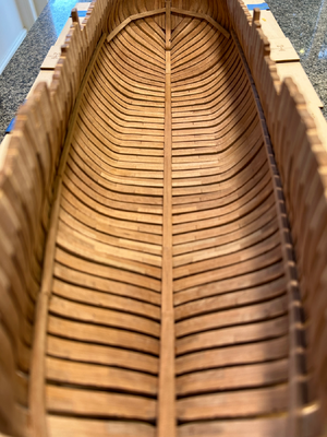
This will be my last post for a while. I know there’s nothing worse than something half finished, but everything - not just models - is becoming a struggle. Hopefully it’s temporary, but I just didn’t want to disappear without warning.
Thanks for your encouragement over the last 12 months. I will be checking SOS occasionally and when I decide to resume building her you will be the first to know.
I hope whatever travails you will pass, and you can return to 'normal' life sooner than later. All the best my friend!
Please don't go for a long time...will look for your posts again.
I am using water based wood glue - so with water you can soften the glue also after weeks -
And I needed this already several times.
Keep care my friend and hope to see you soon here in the forum
And I needed this already several times.
Keep care my friend and hope to see you soon here in the forum
Hallo @SaltyFellow modellers
This is my diary of building La Salamandre 1752 using a kit purchased from CAF.
View attachment 361242
La Salamandre may not as popular as some other ships, but there are enough examples being built on forums so I am not completely by myself. I like the idea of a partially planked hull showing the frames and below decks, as well as the fact that she is rigged. There are some great examples being built from this kit - Koreets, Uwek, ADC, BigMike and Tedboat - and I will be happy if mine turns out half as well.
I don’t intend to do a review of the kit as this topic seems to be well covered by Uwek and others. I am pleased with the quality of the parts, but obviously assembling them is the challenge. The instructions are basic, but at least they provide a sequence for building. Hopefully, I can work out how each step should be undertaken to achieve the necessary results. Tom at CAF is a pleasure to deal with.
To help, I have a copy of the Boudroit and Berti monograph, as well as Frolich’s The Art of Ship Modelling which has a section devoted to this ship. I also have a small collection of other nautical books bought over the years, including Marquardt’s Eighteenth Century Rigs and Rigging, Harland’s Seamanship, as well as a number on traditional wooden boat building and rigging.
I am using a few basic hand tools. I don’t have any power tools, although I might change my tune when it comes to bolts and treenails. At present, my “workshop” is the end of the kitchen table.
I don’t expect this will be a quick build by any means, but I hope you will find it interesting.
Salty
we wish you all the BEST and a HAPPY BIRTHDAY


