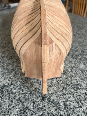
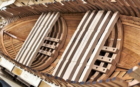
A convincing fix. Hopefully it won’t create issues downstream.
-

Win a Free Custom Engraved Brass Coin!!!
As a way to introduce our brass coins to the community, we will raffle off a free coin during the month of August. Follow link ABOVE for instructions for entering.
-

PRE-ORDER SHIPS IN SCALE TODAY!
The beloved Ships in Scale Magazine is back and charting a new course for 2026!
Discover new skills, new techniques, and new inspirations in every issue.
NOTE THAT OUR FIRST ISSUE WILL BE JAN/FEB 2026
You are using an out of date browser. It may not display this or other websites correctly.
You should upgrade or use an alternative browser.
You should upgrade or use an alternative browser.
La Salamandre 1752 1:48 (CAF) by Salty
- Thread starter Salty
- Start date
- Watchers 24
-
- Tags
- caf model la salamandre
Salty, I continue to be impressed with the quality of this kit, and your ingenuity in building her. That was a nice save on the hawse pieces, and I agree that it's difficult to see how and why that discrepancy arose in the first place. It is a very good repair, though, and one that should give you peace of mind, even though it won't be seen.
- Joined
- Mar 1, 2023
- Messages
- 144
- Points
- 213

Paul and Marc, thanks for your reassurances about the repair. It seems there’s no real damage to La Salamandre, just my nerves, but they’ll recover. I plan on posting a review about my experience with the kit in the not too distant future.
The next step is to install the filler blocks under the hawse pieces. Here are the pieces glued:
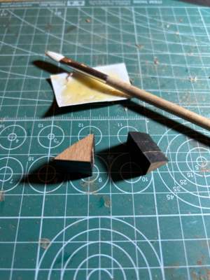
And here are the blocks shaped:

Most of the material was removed with a rasp, but it was a slow process to whittle them down to final dimensions with a knife and lots of test fittings.
The next step is to install the filler blocks under the hawse pieces. Here are the pieces glued:

And here are the blocks shaped:

Most of the material was removed with a rasp, but it was a slow process to whittle them down to final dimensions with a knife and lots of test fittings.
You are making great progress, Salty. I am in synch with Kuba91nt, the hull looking good, nice, and clean (accurate).
- Joined
- Mar 1, 2023
- Messages
- 144
- Points
- 213

With the hawse pieces installed, I have reached the end of the first stage of La Salamandre, at least according to the instruction book - 40 diagrams spread over 8 pages. Unfortunately, the second stage consists of 296 diagrams over 62 pages so we may be here a while longer…
I didn’t do a review of the kit at the beginning, partly because I hadn’t actually tried to build any of it. Having progressed this far, I might now venture an opinion for anyone interested.
CAF Models are in some ways the poor man’s equivalent of a scratch built model - perfect for anyone who wants all the detail in building a hull in much the same way as it would have been done in practice, but isn’t quite willing to take the plunge. Tom at CAF provides accurately marked and cut parts from the correctly sized stock and then everything needs to be finished and assembled. For me, there’s more than enough interest in that and, with patience and some basic skills, I hope to end up with something presentable. I understand criticism about the lack of instructions but I am not sure I necessarily share it. With the amount of effort already required to build such a kit, I think it is reasonable to expect a person to be able to work most things out. In some ways, it’s just another facet of the kit.
Having said that, I don’t think I could build La Salamandre without Boudroit and Berti, although it may well be possible to do so depending on the experience of the builder. The CAF plans are certainly based closely on Boudroit and Berti, but aren’t identical. It seems to me that CAF have made some well thought out changes - e.g. hawse pieces, stern and deck framing - to simplify various elements to make her more buildable, but you will still get a ship that is historically accurate in most respects.
Granted, the kits are not cheap, but when you think about how much time is invested in a model - in my case, probably 250+ hours to date just for the hull framing - it is relatively inexpensive as a past-time.
You need surprisingly few tools for the kit. To date, I have mainly used sanding sticks (with good quality 120-320 grit sanding belts on cloth backing), a small rasp, a musical instrument makers knife, single edged razor blades, a 6” steel ruler, a few clamps and some glue. I also have 6” bench hook which I have very useful as a brace for holding parts while working on them.
I would thoroughly recommend the kit to anyone who wants to invest the time and effort but it’s certainly not for everyone by any means.
Finally, I would like to thank everyone who has been following my progress. It’s been a little terrifying to have so many people looking at my work, but I think it has pushed me keep at it and not settle for second best. If there’s any burning questions, I’d be happy to try to answer them.
On to part 2 of the kit…
Thank you for opinion. The model is great for learning POF. If you start straight from the monograph, there is a big collision with elements that have to be shaped in 3D. And there's the problem of tools. You can't buy everything at once, over time you can collect tools and start a specific ship, I think that after one such model, a more complicated monograph becomes easy. At the beginning I had a very big problem with forming the frame grinding lines, now I understand. The instructions are also very helpful, when making a model you have to think and you learn faster.
well spoken - and I fully agree with your wordsWith the hawse pieces installed, I have reached the end of the first stage of La Salamandre, at least according to the instruction book - 40 diagrams spread over 8 pages. Unfortunately, the second stage consists of 296 diagrams over 62 pages so we may be here a while longer…
I didn’t do a review of the kit at the beginning, partly because I hadn’t actually tried to build any of it. Having progressed this far, I might now venture an opinion for anyone interested.
CAF Models are in some ways the poor man’s equivalent of a scratch built model - perfect for anyone who wants all the detail in building a hull in much the same way as it would have been done in practice, but isn’t quite willing to take the plunge. Tom at CAF provides accurately marked and cut parts from the correctly sized stock and then everything needs to be finished and assembled. For me, there’s more than enough interest in that and, with patience and some basic skills, I hope to end up with something presentable. I understand criticism about the lack of instructions but I am not sure I necessarily share it. With the amount of effort already required to build such a kit, I think it is reasonable to expect a person to be able to work most things out. In some ways, it’s just another facet of the kit.
Having said that, I don’t think I could build La Salamandre without Boudroit and Berti, although it may well be possible to do so depending on the experience of the builder. The CAF plans are certainly based closely on Boudroit and Berti, but aren’t identical. It seems to me that CAF have made some well thought out changes - e.g. hawse pieces, stern and deck framing - to simplify various elements to make her more buildable, but you will still get a ship that is historically accurate in most respects.
Granted, the kits are not cheap, but when you think about how much time is invested in a model - in my case, probably 250+ hours to date just for the hull framing - it is relatively inexpensive as a past-time.
You need surprisingly few tools for the kit. To date, I have mainly used sanding sticks (with good quality 120-320 grit sanding belts on cloth backing), a small rasp, a musical instrument makers knife, single edged razor blades, a 6” steel ruler, a few clamps and some glue. I also have 6” bench hook which I have very useful as a brace for holding parts while working on them.
I would thoroughly recommend the kit to anyone who wants to invest the time and effort but it’s certainly not for everyone by any means.
Finally, I would like to thank everyone who has been following my progress. It’s been a little terrifying to have so many people looking at my work, but I think it has pushed me keep at it and not settle for second best. If there’s any burning questions, I’d be happy to try to answer them.
On to part 2 of the kit…
- Joined
- Mar 1, 2023
- Messages
- 144
- Points
- 213

I have begun to look at where deck clamps go. Although the plans say the ceilings go in next, if I put the clamps in beforehand it will help with the measurements.
The kit specifies 3 x 5 mm. There are two sections - one from the stem to frame 9 and another from frame 9 to the transom. No specifics are provided about the clamp heights, but I think the beams simply sit on top of the clamp and butt up against the frames.
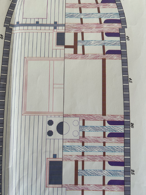
The beam heights are shown in a longitudinal cross-section of the hull.
Boudroit and Berti show a more complex arrangement. The clamp is 3 x 7 mm and the beams sit in notches in the clamp. Some pass through the clamp to butt against the frames while others finish short of the frames. They are set into the clamp with a dovetail joint.
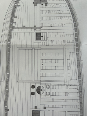
I am happy to go with the simplified arrangement. While it’s not historically accurate, I think it’s a close enough approximation and I stand a fighting chance of actually building.
This description took about three days of investigation. I think the effort was worth it as the clamps and the beams are reference points for lots of other parts of the ship. It’s also prompted a better understanding of how ships were built so I don’t see it as wasted time at all. As I mentioned in my review, while the CAF kit does follow Bourdroit and Berti quite closely, it is clear there are differences to simplify some details to assist in building without unnecessarily compromising the accuracy.
This will be my last entry for 2023, so I wish you all a Merry Christmas and I’ll be back in the New Year.
The kit specifies 3 x 5 mm. There are two sections - one from the stem to frame 9 and another from frame 9 to the transom. No specifics are provided about the clamp heights, but I think the beams simply sit on top of the clamp and butt up against the frames.

The beam heights are shown in a longitudinal cross-section of the hull.
Boudroit and Berti show a more complex arrangement. The clamp is 3 x 7 mm and the beams sit in notches in the clamp. Some pass through the clamp to butt against the frames while others finish short of the frames. They are set into the clamp with a dovetail joint.

I am happy to go with the simplified arrangement. While it’s not historically accurate, I think it’s a close enough approximation and I stand a fighting chance of actually building.
This description took about three days of investigation. I think the effort was worth it as the clamps and the beams are reference points for lots of other parts of the ship. It’s also prompted a better understanding of how ships were built so I don’t see it as wasted time at all. As I mentioned in my review, while the CAF kit does follow Bourdroit and Berti quite closely, it is clear there are differences to simplify some details to assist in building without unnecessarily compromising the accuracy.
This will be my last entry for 2023, so I wish you all a Merry Christmas and I’ll be back in the New Year.
- Joined
- Mar 1, 2023
- Messages
- 144
- Points
- 213

With Christmas and New Year out of the way, it’s back to ship building.
Today I started on the floor riders:
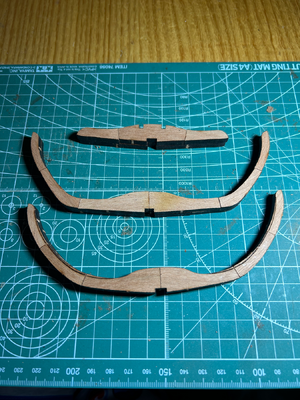
The floor riders are constructed in the same way as the frames - glued up two layers and the remove laser charring.
There’s some method in this madness in starting something new - the two largest riders come up to the level of the underneath edge of the deck beams. I can check if I have the clamp level correct.
I am also waiting on some clamps to arrive which I will need for the clamp itself. The clamps have a jaw depth of about 120 mm and jaw width of 40 mm. Clamping through the hull isn’t practical as there is only a 2 mm gap between frames. Heaven only knows why I didn’t order them earlier. They’re somewhere between Germany and Australia with all the other late Christmas presents still in transit. I will forgive you if you’re thinking this bloke isn’t the sharpest knife in the draw…
Today I started on the floor riders:

The floor riders are constructed in the same way as the frames - glued up two layers and the remove laser charring.
There’s some method in this madness in starting something new - the two largest riders come up to the level of the underneath edge of the deck beams. I can check if I have the clamp level correct.
I am also waiting on some clamps to arrive which I will need for the clamp itself. The clamps have a jaw depth of about 120 mm and jaw width of 40 mm. Clamping through the hull isn’t practical as there is only a 2 mm gap between frames. Heaven only knows why I didn’t order them earlier. They’re somewhere between Germany and Australia with all the other late Christmas presents still in transit. I will forgive you if you’re thinking this bloke isn’t the sharpest knife in the draw…
- Joined
- Mar 1, 2023
- Messages
- 144
- Points
- 213

Ken, thanks for your kind words. I am trying my best with both La Salamandre and the log. I am enjoying your efforts on HMS Blandford and really admire your practical, no nonsense approach to modelling.
Here are the finished floor riders in place in the hull:
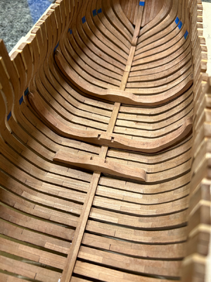
No glue yet as they go in after the ceiling planking, hence the reason for the gap between the rider and the frame. Clamp looks to be in the right spot which is good.
Here are the finished floor riders in place in the hull:

No glue yet as they go in after the ceiling planking, hence the reason for the gap between the rider and the frame. Clamp looks to be in the right spot which is good.
Looking very good -
correct - the floor riders have be adjusted finally and lockated on top after the planking is installed
correct - the floor riders have be adjusted finally and lockated on top after the planking is installed
- Joined
- Mar 1, 2023
- Messages
- 144
- Points
- 213

Thank you again for all who are viewing my progress. I’m a little embarrassed by how slow it has been compared to some others, but I’ll keep persevering. Thanks also to Uwek for confirming about the riders. The clamps just have to be right as everything else depends on them.
I have been putting some bolts in the riders:
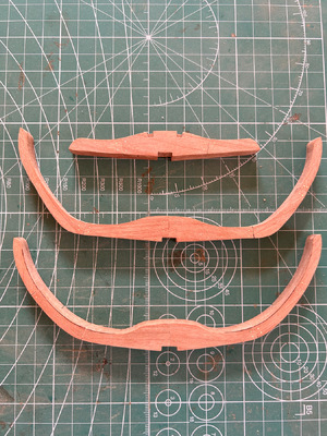
They are 0.5 mm brass wire. Not too difficult. Thankfully, the nippers cut relatively flush, so it only takes a few swipes of a sanding stick to finish. I think the effect will be OK (perhaps a little on on the small side?), especially after some sort of finish like shellac. The cherry is actually quite pink straight after sanding, but seems to darken a bit over time, so there might be a bit more contrast later.
I am not sure to what extent I will do other parts of the ship at this stage. La Salamandre must have been riddled with bolts, spikes and treenails and I am a little wary about going too far and spoiling the look of the wood.
I feel like a proper ship modeller now that I have done some bolts, but will probably end up loathing them after the next thousand or so.
I have been putting some bolts in the riders:

They are 0.5 mm brass wire. Not too difficult. Thankfully, the nippers cut relatively flush, so it only takes a few swipes of a sanding stick to finish. I think the effect will be OK (perhaps a little on on the small side?), especially after some sort of finish like shellac. The cherry is actually quite pink straight after sanding, but seems to darken a bit over time, so there might be a bit more contrast later.
I am not sure to what extent I will do other parts of the ship at this stage. La Salamandre must have been riddled with bolts, spikes and treenails and I am a little wary about going too far and spoiling the look of the wood.
I feel like a proper ship modeller now that I have done some bolts, but will probably end up loathing them after the next thousand or so.
- Joined
- Mar 1, 2023
- Messages
- 144
- Points
- 213

My apologies but I couldn’t post last night as usual because of a technical glitch with SOS but it seems to have been rectified by our hard-working administrators.
Uwek, thanks for your post. I hadn’t thought about showing bolts fixing the riders in place, but obviously there should be some. It might be easier to put the bolts in before I install the riders rather than try to wrestle the hull steady while I drill. I have been following your Granado with just as much interest as your La Salamandre. Compulsory reading for anyone interested in plank on frame models.
Over the last few nights, I have been making some eyes bolts with rings:
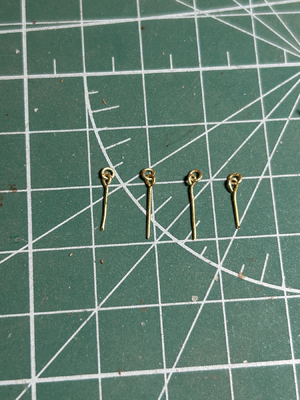
These go in the chocks which wedge the mast in the mast step between the floor riders.
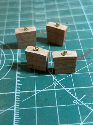
They are made with 0.5 mm brass wire. I have magnifying reading glasses - the type you get from the chemist - that I use for most close work, but they almost weren’t enough for this job. If anything, the eyes are a little oversized but I think the rings are about right. The shanks on the eyes were trimmed to a few millimetres when I fitted them.
The CAF instruction booklet shows the eyes, but I can’t find any etched parts and materials aren’t provide to make them. Boudroit and Berti show them but only as part of a longitudinal drawing of the hull.
Uwek, thanks for your post. I hadn’t thought about showing bolts fixing the riders in place, but obviously there should be some. It might be easier to put the bolts in before I install the riders rather than try to wrestle the hull steady while I drill. I have been following your Granado with just as much interest as your La Salamandre. Compulsory reading for anyone interested in plank on frame models.
Over the last few nights, I have been making some eyes bolts with rings:

These go in the chocks which wedge the mast in the mast step between the floor riders.

They are made with 0.5 mm brass wire. I have magnifying reading glasses - the type you get from the chemist - that I use for most close work, but they almost weren’t enough for this job. If anything, the eyes are a little oversized but I think the rings are about right. The shanks on the eyes were trimmed to a few millimetres when I fitted them.
The CAF instruction booklet shows the eyes, but I can’t find any etched parts and materials aren’t provide to make them. Boudroit and Berti show them but only as part of a longitudinal drawing of the hull.
- Joined
- Mar 1, 2023
- Messages
- 144
- Points
- 213

Here are the completed chocks sitting in the mast step:
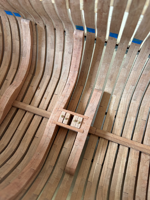
The chocks will need to be shaped when the mast is fitted, but that’s another story.
This little piece is a great example of how accurately the parts are cut. The notches in the floor riders are cut slightly off vertical so the pieces joining them angles inwards to match the chocks. And the tenons are just long enough to fit perfectly into the notches. That’s not to say that there was some work required to get it to go together, but it is a pleasing result all the same.
Very good accurate work - a good kit meets a good modeler -> and will result in a very good model


