La Toulonnaise 1823 - French schooner Artesania Latina 1:70 by Jeff W

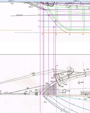
In both the Profile Plan and Half Breadth Plan, the Waterlines should intersect with the Inside Stem Line and the Inside Keel Line. These intersection points should match.

As you can see in the attached TurboCAD drawing, using the museum plans I drew projection lines from the intersection points on the Half Breadth Plan upward to the Profile Plan, but they don't intersect with the Inside Stem Line and the Inside Keel Line at the same points as the Waterlines on the Profile Plan.

Definitely errors somewhere in the museum plans. Not sure how this problem came about originally when the plans were drawn up, but it raises concerns about the actual body shape of the ship.

TurboCAD Waterlines anomaly.jpg
 
Last edited:
At the very least, it would seem that the projection lines should originate from the Profile rather than the Half-breadth Plan, and so should be adjusted to come down from the intersection of the horizontal Waterlines with the Inner Stem Line on the Profile Plan, on down to the Half Breadth Plan Keel and Stem lines to provide new end points for the Waterlines on the half-breadth plan.
 
Last edited:
I would tend to think that the Profile and the Body Plan should be regarded as the more accurate representation of the shape of the ship and any anomalies between the two and their corresponding projections be corrected. And only then should the projections be made and measurements used from the Profile and Body Plan to create the Half-breadth Plan. At least for a start on the road to accuracy.
 
Last edited:
Well for those that may find the following information potentially useful, I’ve decided to reconstruct the various plan profiles from the set of A4 scans I made of the French Museum plans.

I first created a blank file using a graphic editing program called Xnview (of which I highly recommend) and enlarged its background canvas to receive “cut and pastes” of each A4 scan in order create an entire profile, cross-section and half-breadth plan, etc, each in its own file. By doing this I manually aligned and matched each A4 scan. I found this to be more accurate a result rather than the “stretch pull” method of compilation employed by the Microsoft Image Composite Editor 2.0.

These separate files I imported into TurbCAD and aligned them as best I could by using projection lines.

I discovered when using the CAD (Computer Aided Drafting) program to loft the plan projections, that the plans for the French Museum model from France are quite inaccurate in many ways that are not obvious by casual cursory observation, so much so, that if one followed the plans directly as presented a whole range of fundamental problems would present themselves during construction.

Consequently, the CAD based lofting process has become quite convoluted, complex and time consuming. A lot of choices have to be made in choosing the ideal “lines” or shapes of the ship and adapting other plan projections to suit, not only to fix errors but to create an accurate depiction of the ship, and that so for construction.

To give an example of what I am talking about here, at the intersections produced by projections from the Section Lines of the Half-breadth plan up to the Shear Line of the Profile Plan, when a line is projected from those intersections across to the Section Plan, they do not intersect to what should be the corresponding intersection of the Sections with the Sheer Line of the Section Plan.

Another example is the Deck Plan half of the Half-breadth Plan is much narrower that the uppermost waterline on the waterline half of the Half-breadth Plan, i.e., the outer extremities of the gunwales are supposed to extend beyond the upper outside edge of the hull. This error was quite unacceptable.

And, although typical of lofting in usually minor ways, but most severely obvious upon measurement with these plans is the difference of measure between waterlines along cross-sections of the Half-breadth Plan compared to that of the Section Plan. Terribly disappointing.

Well amendments are ongoing well beyond that normally expected for lofting, but beyond the intermittent frustration a sense of satisfaction nonetheless.

Happy ship building to one and all.

“I don't know half of you as well as I should like, and I like less than half of you half as well as you deserve.”

Cheers!
 
Last edited:
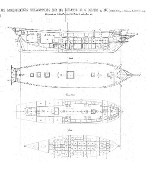
In my pursuit to find information to verify the original hull shape of the vessel, most particularly the shape of the bow, I have discovered another set of old model plans for the La Toulonnaise, from a German company, Modell-Werft. They are quite detailed and appear quite convincing. I shall use these for further comparison with the other plans and photos I have obtained.Modell-Werft Plans.jpg
 
Last edited:
Following with interest, I see there are differences between the resources you have found, is it a case of picking a side and sticking with it.
 
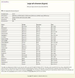
I found information online from a Mr. Stephen S. Roberts at >>>https://www.shipscribe.com/marvap/610b.html<<<:
Info - IRIS class large sail schooners - 6 guns.jpg

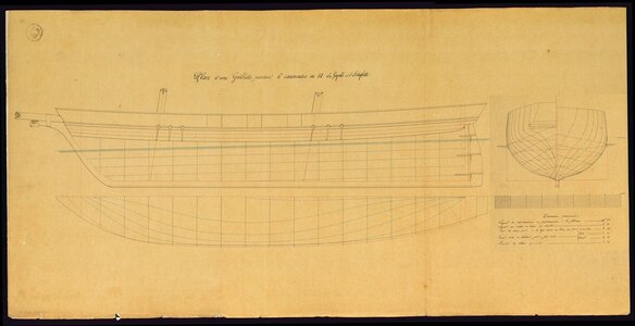
In this table Mr. Roberts provides significant information that the four ships, ESTAFETTE, GAZELLE, HIRONDELLE and TOPAZE were repeat builds of the TOULANNAISE. Happily, I have also found a good quality hi-res original plan of the La Gazelle and l'Estafette from an Italian online site >>>https://unire.unige.it/handle/10621/358<<< namely, the University of Genova (Università degli studi di Genova) in their repository of drawings and plans for the Royal Navy High School. The plan is reproduced below, I have amended the plan to match the orientation of other plans which contain details such as deck plan information, layouts, rigging, sails, etc.:

00 Plan d'une Goëllette portant 6 caronades de 18 La Gazelle et l'Estafette.jpg

I am quite satisfied that this is the best source plan I have been willing and able to find that verifies most closely and accurately the original La Toulonnaise, and have consequently decided to use this plan as the foundation for the build.

I have imported this plan into TurboCAD and scaled it to the true length of the ship, 1:1, (such that 1 metre represented on the plan equals one metre in TurboCAD, one doesn't need to know the original scale of the plan to do this) and have subsequently scaled all other imported plans (both real life plans and model plans) to match it by scale and dimension.

Next step is to draw up the lofting of this ship, design the model false keel structure and print it out at a scale to match the kit and start building.

I do hope this information proves useful.
 
Last edited:
Back
Top