Le Coureur 1776 CAF Model by OT1138

In conjunction with nailing, I've also completed fitting of the port side wales. Despite careful measuring of the upper Wales, I found them to be slightly off when fitting the lower Wales so they had to be adjusted.

Once done, the wales were sanded flat and will be painted, lacquered and nailed as on the starboard side.

I am very tempted to work on the stern and her decorations next but it's not clear to me if this can be done prior to completing the planks above the wales. These in turn require the gunports to be cut, which are dependent on the decks. It could be quite a long time if this is the case.
 
I am very tempted to work on the stern and her decorations next but it's not clear to me if this can be done prior to completing the planks above the wales. These in turn require the gunports to be cut, which are dependent on the decks. It could be quite a long time if this is the case.
The order has to be checked very much in detail - my first opinion is really to finalize either the wales and the planking upper to the wales first - I guess it will bea easier amd more accurate to cut (sand) them at the stern to the correct length, so that the upper counter with the railing will fit exactly and covers all of the planking
The CAF-model
55a.jpg QQ图片20201006015649.jpg

and the scratch model
monographie-du-coureur-lougre-1776 (2).jpg

BTW: Very good work on the nailing of the planking :cool:
 
Completed nailing on the starboard wales and took the opportunity to test drive the yellow ochre on plank 2. I am quite happy with it.

Boudriot's theoretical diagonal nailing pattern does not fit reality on frames 2-4. The tangent of these frames is much wider than the usual 4mm, so some artistic interpretation is required.

I pretty much gave up on trying to fit the bow planks into the rabbet on this model. Maybe next time.

1615681569907.png

1615681660368.png
 
Looking very good - also the painted plank is looking good
Boudriot's theoretical diagonal nailing pattern does not fit reality on frames 2-4. The tangent of these frames is much wider than the usual 4mm, so some artistic interpretation is required.
Boudriot is often telling the modeler the principles which should be followed - in such areas like close to the bow these information have to be adjusted according the technical correct requirements.
in this skecth I tried to show the principles for the normal frame and the extreme frame close to the bow (cross section with view from the top, red is frame, green the plank and blue the bolts / nails)
IMG-5501a.jpg
 
I pretty much gave up on trying to fit the bow planks into the rabbet on this model. Maybe next time.

this is really a tricky area - I had also to deepen the rabbet to the end of the wales were inside the rabbet
If you look close you can still see the small open spot under the wale (which I still have to close)
IMG-5856a.jpg
 
**#$@ these $@#! nails...

Anyone have a technique for getting straight nail lines? I am constantly redoing holes to fix the most misaligned ones and even then, the lines are far from perfect.
 
Last edited:
Here's an example. I used a template to mark straight lines. They looked great. But after drilling holes and inserting nails, they came out quite crooked.
 

Attachments

  • IMG_20210319_154100.jpg
    IMG_20210319_154100.jpg
    125.9 KB · Views: 25
  • IMG_20210319_154938.jpg
    IMG_20210319_154938.jpg
    107.5 KB · Views: 25
  • IMG_20210319_165455.jpg
    IMG_20210319_165455.jpg
    179.8 KB · Views: 25
I couldn't live with these crooked rows of nails so I determined that I would fill all of the existing holes and try again. This might leave some marks but worth trying. If it doesn't work, there counter planks could always be replaced.

The nails were removed, the holes filled and a grid was marked in pencil. I also increased the magnification on my optics for improved accuracy. The holes were carefully redrilled where needed. This was difficult because many were off by .5mm or less. To deal with this, I widened the holes so that I could adjust the nail.

A test fit looked good so I proceeded. The end result was much, much better than before (though not perfect). I could at least live with this!
 

Attachments

  • IMG_20210320_083026.jpg
    IMG_20210320_083026.jpg
    126 KB · Views: 13
  • IMG_20210320_083515.jpg
    IMG_20210320_083515.jpg
    149.3 KB · Views: 13
  • IMG_20210320_085259.jpg
    IMG_20210320_085259.jpg
    141.9 KB · Views: 13
Decided to move on to the puzzle of the stern. This is my first time modeling something this complicated so I certainly am making some mistakes along the way. However, there's a good chance this will help everyone else so there are a few more photos this time.

I began by cutting out the outer rails and cleaning them up. Looks like they have been cut oversize, a good thing as my sanding took off some of the clean cuts on the ends.

1616259854165.png

I went to look for the bottom rail and I discovered it was missing. I had two packages marked 04, so looks like a packing error. You all may want to check your parts. I sent a message to @CAFmodel to get a replacement as well as an extra uncut 1.5mm board, in case things go sideways here.

1616259941579.png

I had no luck figuring out how the border, stern planks (all one piece) and side planks/wales are supposed to fit together. So I kept loosely fitting things together and sanding down the side planks. Unfortunately, I discovered too late that I went too far. I sanded the planks flush with the rear stern assembly. However, this is no good because the side rails are apparently meant to sit on top of the stern planks. Ouch.

Here you see I shaved planks 1 and 2 flush with the stern. I left the wales because they sit (mostly) outside of the area of the stern.

1616260077563.png

This is about the time I discovered that this approach results in a "stern sandwich", with the side of the stern piece being visible between planks 1+2 and the railings.

1616260170099.png

1616260188201.png

A cross check with the plans confirms that the rails are intended to sit on top of the stern piece, and not flush to the sides.

Also note that the thin wood pieces in between each window are extremely fragile. Mine lasted about 5 minutes.

1616260240499.png

Here you can see how far to the side the wales sit. They will extend beyond the rails.

1616260314562.png

1616260328071.png

1616260354860.png

Here's a better photo showing how I want the rails to sit... flush with the wales and upper planking:

1616260422256.png
 
I stepped away for a bit to gather my thoughts. It then occurred to me that the stern has to fit within a pocket formed by the side planks and the lower stern counter. The sides should be (at least mostly) covered by those planks so that the rail can sit flush on the rear and hide the joints.

Sadly, my inexperience was hurting me here. I had already sanded the side planks flush with the rear. What to do?

Then inspiration... I broke out my brand new set of Veritas mini chisels.

1616260588553.png

Using them, I shaved the sides of the stern framing to create a pocket. The stern pieces is 1.25mm deep but I was hesitant to cut that far as it could weaken the structure, especially the upper "batman" stick. I ended up chiseling out around 0.8mm or so, figuring I could sand the stern piece down a bit more quite safely.

1616260638124.png

1616260735777.png

After the rear stern piece was sitting almost flush with the side planks, I then discovered that the stern piece needed to be fitted so that it could sit next to the planks. I did this by marking the area of overlap with a pencil and then shaving away a notch using the chisels.

1616260870937.png

Here we see that the stern piece is now flush to the side planks... that is, except for the half below where it split. No worries, all of the wood just to the right of the window cutout broke off a few seconds later.

1616262487475.png

Finally, I summoned my courage and glued the stern piece on (photo taken before glue cleanup). It is now drying.

1616262556280.png
 
After removing the clamps, the damaged areas are now visible. These were patched with custom made pieces and sanded flat. The railings were checked for flatness. I then filed out the plank lines and applied a layer of stain.

IMG_20210320_142446.jpg

IMG_20210320_155453.jpg

IMG_20210320_165748.jpg
 
Last edited by a moderator:
Very good work and many thanks for the informative photos showing the details of this challenge.
One comment with your nailing work on the stern.
Drilling through the paper is producing this problem, because your drill is slippering a little bit.
The best way is how you did with your repair with marking a fine line with a pencil directly on the timber - I make in addition some small depening with a scriber.

51cwZDAb3kL._SX679_.jpg

With this the drill has a small but very effective guide.....

Here you can see the dotts with scriber and the other row already drilled
Unbenannt-scriber.JPG
 
Ah, I should have explained better. The holes in the paper are from a pencil lead. I used those to mark the initial holes, then traced a "best fit" line through them with a straight edge. These lines were perfectly straight, yet the drill itself seems to move a little bit (perhaps when making the pilot hole). I also did not draw horizontal lines and instead relied on the planking for reference points.

A scribe is a wonderful idea... a pencil lead is about 0.5mm across or so, which does not appear to have the tolerance needed for this work.
 
The stern is very complicated.

So rather than deliberate any further, I decided to start with the bottom rail as the placement of the outer decorative rails depend on it. The instructions call for a molded 1.5mm strip to be used but I could not locate any of these in the kit (I had assumed before that there was a package with this piece but apparently this is not the case). There were however 1.5mm strips included.

A quick trip to the hardware store yielded a small stainless steel strip. With a few practice runs, I finally succeeded in filing a decent molding pattern into a 1.7mm wide slot:

1616970429781.png

I then scraped this pattern into a 1.5mm strip and eventually a nice contour formed. I note that I could not replicate the same pattern seen on the outer decorative rails in such a tiny space, but it came out pretty good!

1616970463089.png

This took a bit of careful bending to get it to match the contour of the counter. This was followed with a layer of yellow ochre.

However, one problem remained: the lower rail would not hide the gap seen between the counter and the stern piece. This would not normally be seen unless one looked from the bottom but still...

I noodled on this for awhile and remembered that in the original vessels, ropes soaked in tar would sometimes be used to seal gaps. Easy enough! I stained a small "rope" in black and glued it into the seam.

1616970069968.png

After gluing the lower rail in place, I then began to wrestle with the outer rails. More to come.

1616970842934.png
 

Attachments

  • 1616970334589.png
    1616970334589.png
    1.5 MB · Views: 5
  • 1616970743798.png
    1616970743798.png
    1.2 MB · Views: 5
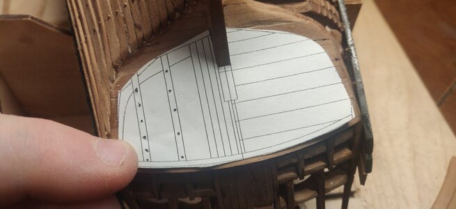
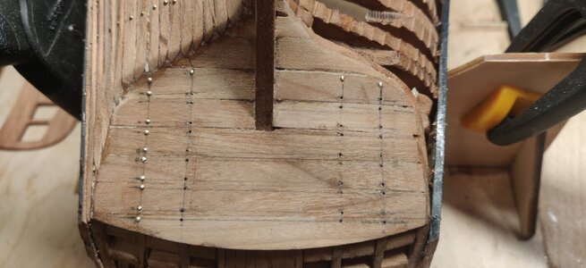
So now about these stern rails. Unless my kit is is a aberration, I predict that most here are going to run into a similar problem that I am right now. Mainly, the upper rail does not match the contour of the stern piece:

1616971061887.png

I had hopes that this piece could be used simply by cutting it a bit shorter, but you can see from the above that there is ~3mm of bend missing from the ends. To confirm this, I traced the pieces onto paper and laid them on the stern. It was not possible to get them to form smooth curves when joined without bending the paper (and I could not bend the boxwood rail, either... I tried but it seems far too brittle).

1616971568240.png

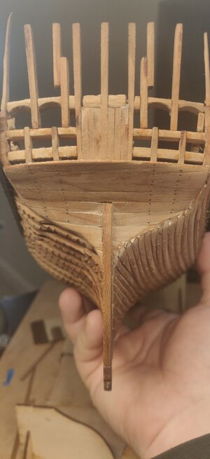
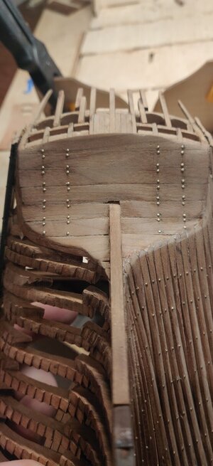
I am not sure how everyone else's models are turning out, but the stern edge of the wales do not sit flush with planks 1+2, but rather jut out a little. How exactly this is to be resolved is not specified in the CAF or Boudriot plans anywhere, so I guess I'm on my own.

I thought I would try a little experiment to see if I can fabricate my own outer rails. I don't have any boxwood on hand but I plan on painting them anyway, so I could use a lower quality wood. I traced the stern on to a piece of paper. While I'm at it, I thought a small rabbet would be nice to hide all the edges where the planks meet the stern piece and cover the top edge of the stern. This measured 1.4mm, so the rabbet will be cut to 1.5mm.

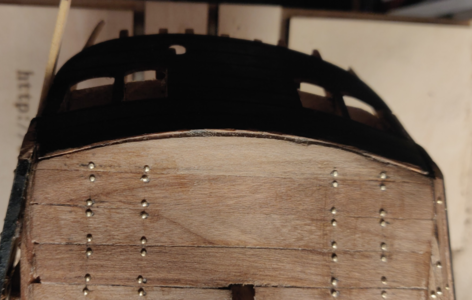
The distance from the outer edge of the wales to the stern piece is 3.5mm, so I'm starting a little larger with 4mm. My pattern is shown below, along with the punch holes I used to transfer it to the wood. Please excuse the rip in the paper.

1616971805607.png

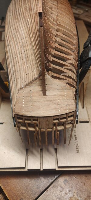
Here's the pattern after transferring it to the wood.

1616972656301.png

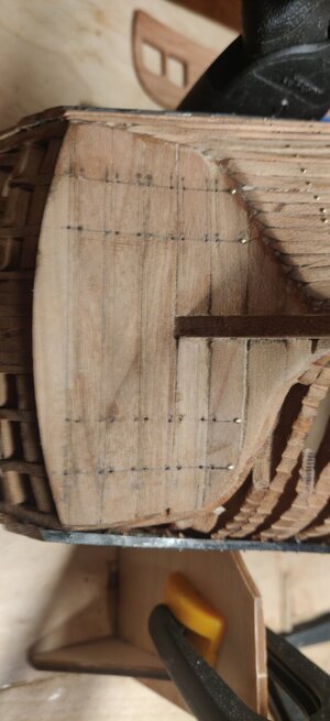
I cut this out roughly with a Dremel diamond cutting disc and then hogged the material out with some small chisels.

1616972706827.png

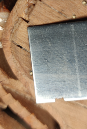
Planed it down exactly to size:

1616977278235.png

Comparing with the original piece below. It's still too wide though it will narrow further after routing the inside. It's also a little too straight in comparison to the original, which has a more pronounced curve.

It remains to be sees if I actually can produce something that can replace the original!

1616977320231.png
 
Back
Top