-

Win a Free Custom Engraved Brass Coin!!!
As a way to introduce our brass coins to the community, we will raffle off a free coin during the month of August. Follow link ABOVE for instructions for entering.
-

PRE-ORDER SHIPS IN SCALE TODAY!
The beloved Ships in Scale Magazine is back and charting a new course for 2026!
Discover new skills, new techniques, and new inspirations in every issue.
NOTE THAT OUR FIRST ISSUE WILL BE JAN/FEB 2026
You are using an out of date browser. It may not display this or other websites correctly.
You should upgrade or use an alternative browser.
You should upgrade or use an alternative browser.
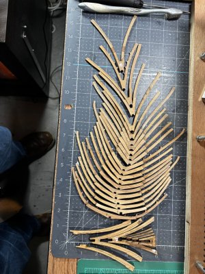
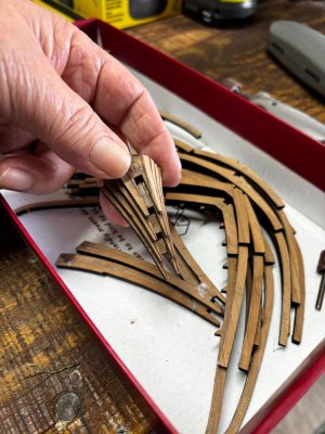
Building frames…it goes on for a while, but as you start placing them on the keel you see the result of your hard work. 
Good afternoon,
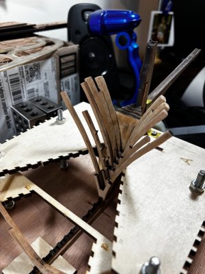
A little progress here with a bit of a problem and my solution. The first 4 forward rib timbers (really more like notched tapered triangles) that go on the stem post portion of the keel along with the first 3 true rib members do not fit properly into the jig. These pieces actually get glued together before placing them in the jig and at the same time using the jig as a guide for glue up. I sanded them to their proper guidelines, cleaning off the majority of the char and then when dry fitting into the jig there is a gap of equal width on each side that I believe should not be there. I know this sounds suspicious, but I have followed every step correctly thus far into fabrication. First the empty jig with arrows that point to the gap location then with the frames dry fitted in place where you can clearly see this gap.


I've studied this thing long enough to believe there is a design disconnect between the jig and the timbers and so have moved on with my solution.
Closing the gap with a jig modification as shown.

As you can see the subsequent frames are quickly filling the jig in a proper manner. Now it is certainly possible that the gaps shown above are a result of my builder error however I was just not able to reconcile it. So, when it comes time to plank the hull I will have to allow for a slightly narrower bow section. The only reason I bring this up is for future builders' consideration. Here are a few more photos showing my method of securing the keel to the jig floor plus some more frames.
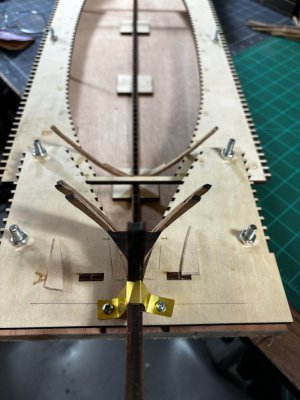
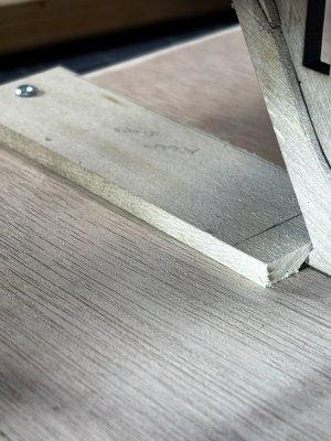
By the way this jig is open enough for easy access to the keel notches for any required sanding.
Hope you enjoyed this, till next time!
A little progress here with a bit of a problem and my solution. The first 4 forward rib timbers (really more like notched tapered triangles) that go on the stem post portion of the keel along with the first 3 true rib members do not fit properly into the jig. These pieces actually get glued together before placing them in the jig and at the same time using the jig as a guide for glue up. I sanded them to their proper guidelines, cleaning off the majority of the char and then when dry fitting into the jig there is a gap of equal width on each side that I believe should not be there. I know this sounds suspicious, but I have followed every step correctly thus far into fabrication. First the empty jig with arrows that point to the gap location then with the frames dry fitted in place where you can clearly see this gap.


I've studied this thing long enough to believe there is a design disconnect between the jig and the timbers and so have moved on with my solution.
Closing the gap with a jig modification as shown.

As you can see the subsequent frames are quickly filling the jig in a proper manner. Now it is certainly possible that the gaps shown above are a result of my builder error however I was just not able to reconcile it. So, when it comes time to plank the hull I will have to allow for a slightly narrower bow section. The only reason I bring this up is for future builders' consideration. Here are a few more photos showing my method of securing the keel to the jig floor plus some more frames.


By the way this jig is open enough for easy access to the keel notches for any required sanding.
Hope you enjoyed this, till next time!
I think your solution works, as long as the frames align along the curve of the hull, then that’s the most important thing. By that I mean the outside surface. If there is gap inside between the frame and jig, that seems like a jig problem and not a frame problem, assuming the outside of the frame is following the natural curve of the hull.Good afternoon,
A little progress here with a bit of a problem and my solution. The first 4 forward rib timbers (really more like notched tapered triangles) that go on the stem post portion of the keel along with the first 3 true rib members do not fit properly into the jig. These pieces actually get glued together before placing them in the jig and at the same time using the jig as a guide for glue up. I sanded them to their proper guidelines, cleaning off the majority of the char and then when dry fitting into the jig there is a gap of equal width on each side that I believe should not be there. I know this sounds suspicious, but I have followed every step correctly thus far into fabrication. First the empty jig with arrows that point to the gap location then with the frames dry fitted in place where you can clearly see this gap.
View attachment 508715View attachment 508716
I've studied this thing long enough to believe there is a design disconnect between the jig and the timbers and so have moved on with my solution.
Closing the gap with a jig modification as shown.
View attachment 508718
As you can see the subsequent frames are quickly filling the jig in a proper manner. Now it is certainly possible that the gaps shown above are a result of my builder error however I was just not able to reconcile it. So, when it comes time to plank the hull I will have to allow for a slightly narrower bow section. The only reason I bring this up is for future builders' consideration. Here are a few more photos showing my method of securing the keel to the jig floor plus some more frames.
View attachment 508720View attachment 508721View attachment 508722View attachment 508723View attachment 508724
By the way this jig is open enough for easy access to the keel notches for any required sanding.
Hope you enjoyed this, till next time!
Yes, I agree Dean. So far, my eyes perceive smooth continuity up to frame # 2. The slots in the jig do flow nicely into my revision at the nose so if the rest of the frames fit the jig, then I think I'll be ok, just need to set a few more frames to be sure.as long as the frames align along the curve of the hull, then that’s the most important thing.
Excellent work. Having built this kit myself a few years ago, I can say its a challenging build.
Its a design flaw - my model had the same gaps at the bow. The other flaw to look at are the triangular extensions on the frames to align the inside plank reinforcements when you get there after installing the frames. Not only do these pose a hinderance when fairing the inside of the frames, they were off alignment for me. I ignored some of them to get a nice run/flow of the planks bow to stern
- Joined
- Oct 12, 2022
- Messages
- 64
- Points
- 88

In fact, ZHL is the overseas distributor, while LuHaiQingKong (also known as YuanQing) is the manufacturer behind this kit. This kit referenced ANCRE’s blueprints, but with original modern designs--such as unfolded and laser cut planking. Anyway, Enjoy!
Good morning Daniel. I have been waiting for this moment and now it is here. This is my favourite ship and from what I have seen the ZHL kit is awesome. I have my lazy boy lined up in the front row.....have fun Daniel. Cheers Grant
Good morning Daniel. Jig Gremlins…Good afternoon,
A little progress here with a bit of a problem and my solution. The first 4 forward rib timbers (really more like notched tapered triangles) that go on the stem post portion of the keel along with the first 3 true rib members do not fit properly into the jig. These pieces actually get glued together before placing them in the jig and at the same time using the jig as a guide for glue up. I sanded them to their proper guidelines, cleaning off the majority of the char and then when dry fitting into the jig there is a gap of equal width on each side that I believe should not be there. I know this sounds suspicious, but I have followed every step correctly thus far into fabrication. First the empty jig with arrows that point to the gap location then with the frames dry fitted in place where you can clearly see this gap.
View attachment 508715View attachment 508716
I've studied this thing long enough to believe there is a design disconnect between the jig and the timbers and so have moved on with my solution.
Closing the gap with a jig modification as shown.
View attachment 508718
As you can see the subsequent frames are quickly filling the jig in a proper manner. Now it is certainly possible that the gaps shown above are a result of my builder error however I was just not able to reconcile it. So, when it comes time to plank the hull I will have to allow for a slightly narrower bow section. The only reason I bring this up is for future builders' consideration. Here are a few more photos showing my method of securing the keel to the jig floor plus some more frames.
View attachment 508720View attachment 508721View attachment 508722View attachment 508723View attachment 508724
By the way this jig is open enough for easy access to the keel notches for any required sanding.
Hope you enjoyed this, till next time!
Agree my was the same, also couple of the rib frames towards the stern needed quite a bit of adjustment to line up properly, but it still great fun to build, hope you enjoy itIts a design flaw - my model had the same gaps at the bow. The other flaw to look at are the triangular extensions on the frames to align the inside plank reinforcements when you get there after installing the frames. Not only do these pose a hinderance when fairing the inside of the frames, they were off alignment for me. I ignored some of them to get a nice run/flow of the planks bow to stern
Hello Bryian, I'm glad you joined in on this build, your input is always valuable to me.Excellent work. Having built this kit myself a few years ago, I can say its a challenging build.
Hello CLB and welcome to my build. Your confirmation of the gaps restores some of my confidence in this build, thank you. I appreciate the heads up with those little triangular extensions and yes, they certainly block a continuous fairing of the hull interior. So, if their alignment is indeed off, I have multiple challenges to overcome.Its a design flaw - my model had the same gaps at the bow.
Hello Jackie Wolf, I love your avatar. I suspected YQ was the manufacture, thanks for the confirmation and welcome to my build log.In fact, ZHL is the overseas distributor, while LuHaiQingKong (also known as YuanQing) is the manufacturer behind this kit. This kit referenced ANCRE’s blueprints, but with original modern designs--such as unfolded and laser cut planking. Anyway, Enjoy!
Thats Sage advice Grant, I surely will proceed with extra caution.definitely sleep on it tho just in case we are all missing something.
Thank you for the confirmation and heads up at the stern kidsgalore.Agree my was the same, also couple of the rib frames towards the stern needed quite a bit of adjustment to line up properly, but it still great fun to build, hope you enjoy it
Hello everyone, I finally have a clear path forward with a workaround at the bow section. Right now, I have just dry fitted the frames you will see coming up. I needed to place enough of em in the jig to see what the curvatures are doing. The lines dictated by the jig are what must be followed at all costs. As you can see the offset between the first two freestanding frames and the nose group is too great to hold a smooth curve. This became visible when I lashed the rib extensions to the jig with rubber bands. Since the nose timbers are solid it dawned on me, I could take some pear strakes (I have plenty extra) and glue them vertically side by side and fill in the gap. As they near the keel/stem post location I will need to tapper them down to nothing so I can properly tie in the hull planking to the rabbit line. At the top of the tall ribs the new verticals will just make those ribs thicker, it may be necessary to fair out the inside a little more but no big deal. have a look at this.
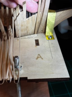
Here is where you can see the offset being too great to overcome hence the vertical fillers.
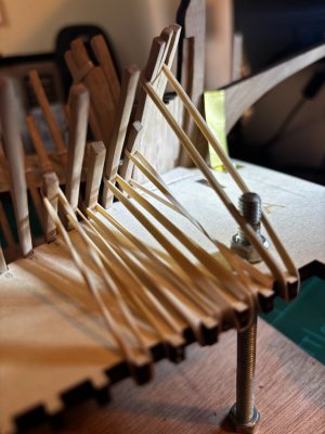

So, for now, I can follow the jig, but I have a feeling that Mr. Murphy is lurking around the corner with a bag full of unintended consequences.
Thanks for checking in.

Here is where you can see the offset being too great to overcome hence the vertical fillers.


So, for now, I can follow the jig, but I have a feeling that Mr. Murphy is lurking around the corner with a bag full of unintended consequences.
Thanks for checking in.
- Joined
- Dec 3, 2022
- Messages
- 1,547
- Points
- 488

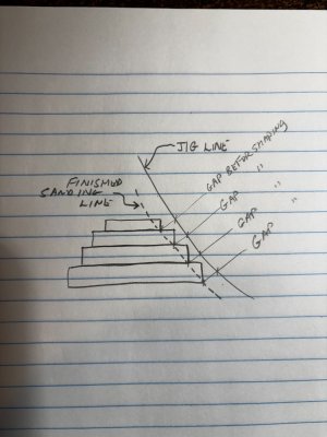
I haven't yet had the courage to unpack my Requin from its boxes so forgive my imperfect understanding of the kit. However, could it be that the gap in the jig was intended to accommodate those triangular pieces of deadwood in an unfaired condition, so that the final shaping could be done when the ship is free?
Thats a great question Smithy, I think this sketch may explain better than I could. The inside corners if you will are already part of the gap before you even begin sanding away. Hope this makes sense.I haven't yet had the courage to unpack my Requin from its boxes so forgive my imperfect understanding of the kit. However, could it be that the gap in the jig was intended to accommodate those triangular pieces of deadwood in an unfaired condition, so that the final shaping could be done when the ship is free?
- Joined
- Jun 17, 2021
- Messages
- 3,200
- Points
- 588

Another example of the mysteries, pitfalls and booby traps these kits inevitably offer up! 


