Thanks Grant, right now I plan on a fully planked deck. I probably will have a grating or two between the canons removable over the false decking underneath and may even leave out some of the deck planking directly under the grating but that would be all. To me the ships big beautiful wide deck needs to be displayed in all her glory.Good morning Daniel. I see how it all fits together now. It makes sense with all the curves in the decking of these ships. It certainly looks like you have owned this -Way to go. I don't know if you are going to leave some of the ship open to see the internal frames etc, but it looks impressive. Cheers Grant
-

Win a Free Custom Engraved Brass Coin!!!
As a way to introduce our brass coins to the community, we will raffle off a free coin during the month of August. Follow link ABOVE for instructions for entering.
-

PRE-ORDER SHIPS IN SCALE TODAY!
The beloved Ships in Scale Magazine is back and charting a new course for 2026!
Discover new skills, new techniques, and new inspirations in every issue.
NOTE THAT OUR FIRST ISSUE WILL BE JAN/FEB 2026
You are using an out of date browser. It may not display this or other websites correctly.
You should upgrade or use an alternative browser.
You should upgrade or use an alternative browser.
A little mistake of me ……. Reading English, thinking in Dutch and then answering in a combination of that.Hi Peter, the sheer of the main support beam looks very good, and it dictates the longitudinal sheer. The curvature of the deck cross beams is in my mind severe, so by adjusting the clamp strakes relative to the main support beam and curvature of the deck beams should yield a pleasing look to the fully planked deck. At some point I will need to cut out a section of the main support beam to allow for the main mast to come through as well as the other openings in the central part of the deck.
Regards, Peter
Thank you Rebus.I haven't gotten to this level of building yet but I think your work looks incredibly!
You’re moving right along. Kudos.
Hello Tony, thanks for stopping by.You’re moving right along. Kudos.
- Joined
- Jan 25, 2023
- Messages
- 543
- Points
- 308

Got you a present, Daniel, from the book "Souvenirs de Marine" by Vice Admiral François-Edmond Pâris, 1889.
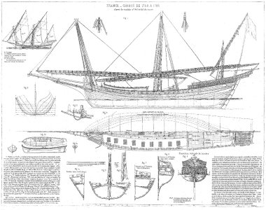
SoS will scale it down, but you can see the full size scan here.

SoS will scale it down, but you can see the full size scan here.
Thank you, Rob! Fig 5 highlights the extreme deck curvature around midship. The canon decking over the top does ease the profile though. I don't recall ever seeing the sails furled and laid down like that either, very cool looking.
- Joined
- Jun 17, 2021
- Messages
- 3,199
- Points
- 588

I've never attempted anything this demanding and difficult, including the restorations, both of furniture and ship models over close to 40 years, and some of those were pretty demanding, with no mistakes allowed. A screwup there would have cost me my livelihood AND reputation! Needless to say, I'm impressed! 


Congratulations on 40 years of excellent craftsmanship Peter. I know from personal experience that is no easy task. I have staked out hundreds of bridges over my 40 years of as a surveyor. I always looked at each bridge as a potential career ending opportunity but never once did I have a situation where the bridge beams did not fit. Like you say a screwup would have cost me my livelihood too. Thank you for your kind impression of my work.I've never attempted anything this demanding and difficult, including the restorations, both of furniture and ship models over close to 40 years, and some of those were pretty demanding, with no mistakes allowed. A screwup there would have cost me my livelihood AND reputation! Needless to say, I'm impressed!

- Joined
- Jun 17, 2021
- Messages
- 3,199
- Points
- 588

Now I get it, Daniel. The internal structure of the Xebec looks a lot like building (a VERY complex) bridge! 

Waaay above my paygrade.


Waaay above my paygrade.
Thats a good guess Rob. It's been noted these types of ships were lighter faster and cheaper to build, the curved deck surface may very well have increased cross section strength instead of much heavier rib sections. These ships were also favored by pirates!My guess is that with the shallower draft and thinner timbers, earlier xebecs were prone to torsional failures. The extreme camber of the deck acted like a cylinder to resist torsion, making the frame more rigid.
- Joined
- Jan 25, 2023
- Messages
- 543
- Points
- 308

Which reminds we, we missed national talk like a pirate day yesterday.Thats a good guess Rob. It's been noted these types of ships were lighter faster and cheaper to build, the curved deck surface may very well have increased cross section strength instead of much heavier rib sections. These ships were also favored by pirates!
Never heard of it! Maybe that's why I have been hearing these irritating pirate commercials on the radio.Which reminds we, we missed national talk like a pirate day yesterday.

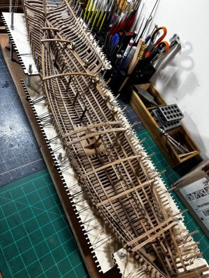
Good morning all, I began placing the deck support beams after making adjustments to the clamp strake layout fore and aft. The ones you see so far, I call the set-up beams, they add rigidity to the longitudinal support beam. Once I finish the set-ups, I will fall back and fill in all the rest.
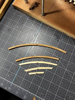
The cross beams are always longer than they need to be giving you a chance to trim them down to fit. If they fall between 2 ribs, it's a simple matter of marking on the beam next to a rib where to make your cuts. If they hit a rib, I found making a copy of the beam onto a thin piece of basswood, cut out the shape then you can place it between the ribs and mark your reference cuts and transfer that to the actual beam for final trimming. The trimmed piece has to conform to the slope of the ribs and the slope of the hull exactly at the top of the clamp strake.

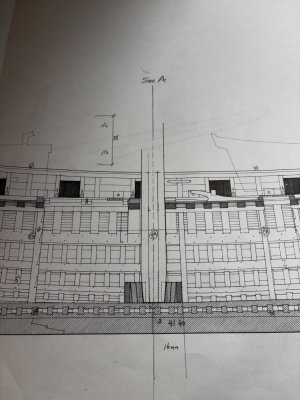
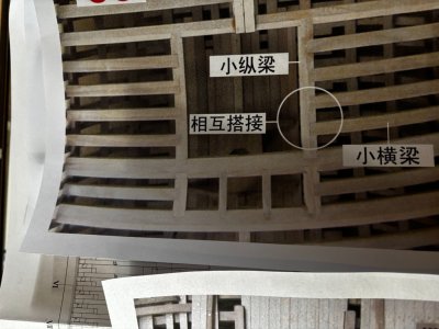
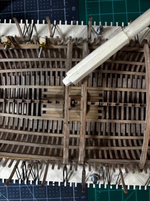
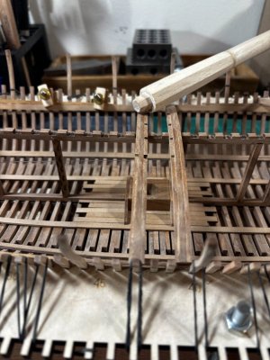
Unfortunately, the mast step does not line up with the opening provided between the two laminated deck beams. I will need to sand down as much as possible on the mast faceted pieces and relocate slightly on the longitudinal beam the notch for the cross beam to accommodate the mast opening through the deck. The first picture below comes from the plans which shows the cross beam slightly covering the mast step below. Now I may be seeing some parallax in their picture but in my build, there is a conflict.
So, the challenges never end on this build. Ha! In today's PC mindset, I must be model building challenged!
Thanks for checking in on me, have a great day.
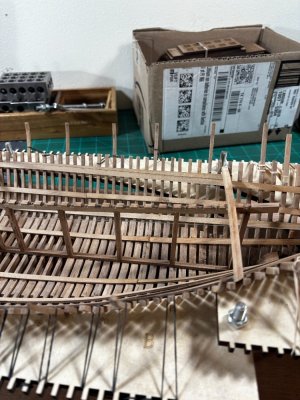

The cross beams are always longer than they need to be giving you a chance to trim them down to fit. If they fall between 2 ribs, it's a simple matter of marking on the beam next to a rib where to make your cuts. If they hit a rib, I found making a copy of the beam onto a thin piece of basswood, cut out the shape then you can place it between the ribs and mark your reference cuts and transfer that to the actual beam for final trimming. The trimmed piece has to conform to the slope of the ribs and the slope of the hull exactly at the top of the clamp strake.


Unfortunately, the mast step does not line up with the opening provided between the two laminated deck beams. I will need to sand down as much as possible on the mast faceted pieces and relocate slightly on the longitudinal beam the notch for the cross beam to accommodate the mast opening through the deck. The first picture below comes from the plans which shows the cross beam slightly covering the mast step below. Now I may be seeing some parallax in their picture but in my build, there is a conflict.


So, the challenges never end on this build. Ha! In today's PC mindset, I must be model building challenged!
Thanks for checking in on me, have a great day.

Hi Daniel, is that mast vertical or does it tip back? Would that help or hurt the current dilemma?
On the Kingfisher the beam locations needed to be precise all along the length of the ship so that other vertical structures could be properly placed (not just the masts). Are there other structures (bitt pins, capstan) you could use to check the placement of that notched center longitudinal piece? (Sorry to be poking around your business - I'm sure you've already studied this extensively - but that central notched bit is where I would begin looking for a solution before I started reshaping things built according to the plans).
I always appreciate your advise Paul. Yes, the logical thing to do is exactly what you say, look ahead for unintended consequences and that is what I will do. There are options I can try, like leave the deck beam where they show it and cut into the beam as required. I need approximately 4mm more of room.On the Kingfisher the beam locations needed to be precise all along the length of the ship so that other vertical structures could be properly placed (not just the masts). Are there other structures (bitt pins, capstan) you could use to check the placement of that notched center longitudinal piece? (Sorry to be poking around your business - I'm sure you've already studied this extensively - but that central notched bit is where I would begin looking for a solution before I started reshaping things built according to the plans).
Good morning Daniel. I've said it before I'm sure these kit manufactures deliberately add some Gremlins in just to challenge us.....Good morning all, I began placing the deck support beams after making adjustments to the clamp strake layout fore and aft. The ones you see so far, I call the set-up beams, they add rigidity to the longitudinal support beam. Once I finish the set-ups, I will fall back and fill in all the rest.
View attachment 546373
The cross beams are always longer than they need to be giving you a chance to trim them down to fit. If they fall between 2 ribs, it's a simple matter of marking on the beam next to a rib where to make your cuts. If they hit a rib, I found making a copy of the beam onto a thin piece of basswood, cut out the shape then you can place it between the ribs and mark your reference cuts and transfer that to the actual beam for final trimming. The trimmed piece has to conform to the slope of the ribs and the slope of the hull exactly at the top of the clamp strake.
View attachment 546376View attachment 546377
Unfortunately, the mast step does not line up with the opening provided between the two laminated deck beams. I will need to sand down as much as possible on the mast faceted pieces and relocate slightly on the longitudinal beam the notch for the cross beam to accommodate the mast opening through the deck. The first picture below comes from the plans which shows the cross beam slightly covering the mast step below. Now I may be seeing some parallax in their picture but in my build, there is a conflict.
View attachment 546375View attachment 546374View attachment 546378
So, the challenges never end on this build. Ha! In today's PC mindset, I must be model building challenged!
Thanks for checking in on me, have a great day.
View attachment 546372
 . That being said this looks like a really cool kit to build and we all know what a beautiful ship the Le Requin is. I would have a look and see if there are any bits, pumps etc which do go down at this beam. If not and you are going to plank the entire deck then I would cut/sand/drill the beam a little to accommodate the mast. I would not move the beam as this could change the curvature of the deck and the length of the carlings etc ?. Just my 2 Cents. Cheers Grant


