Sorry to hear about your bad ‘break’. Hoping for an uneventful and full recovery.
-

Win a Free Custom Engraved Brass Coin!!!
As a way to introduce our brass coins to the community, we will raffle off a free coin during the month of August. Follow link ABOVE for instructions for entering.
-

PRE-ORDER SHIPS IN SCALE TODAY!
The beloved Ships in Scale Magazine is back and charting a new course for 2026!
Discover new skills, new techniques, and new inspirations in every issue.
NOTE THAT OUR FIRST ISSUE WILL BE JAN/FEB 2026
You are using an out of date browser. It may not display this or other websites correctly.
You should upgrade or use an alternative browser.
You should upgrade or use an alternative browser.
Longlegs55 builds ZHL Soleil Royal
- Thread starter Longlegs55
- Start date
- Watchers 14
Neil, I guess your avatar should be called brokenlegs instead of longlegs. If you are talking about the front part of the transom, I think I used the beech, not the sapelle. Sapelle wouldn't fit aesthetically. Whatever I used fit okay. Maybe you could send a picture. One would be worth a thousand words, you know. And so sorry for the pain. The Admiral won't let me get on extension ladders anymore (at least when she's looking).
NO legs jokes. Bad form. Hope you heal up fast! Yikes.good morning, afternoon, evening, fellow modellers. sorry for the absence but had a fight with an extending ladder.
as i am sure you will all know, i lost!! double leg break and dislocated and fractured ankle so i have been about as interested in model making as plaiting fog!!
I blame the Mrs, she wanted stuff from the loft! However if she sees this post it will probably be my last!
Back to this ZHL SR, and more questions. on the "instructions" the front section and rear transom are stated as P3 which is 6mm beech but i saw on one log, i have been reading many, they said P13 which is 3mm sapele. they are both different thicknesses, the beech being 0.5mm and the sapele 1mm. Perssonally i think it should be the sapele but that will sink the gunports deeper than the rest of the model. Suggestions please!!!!
Also whoever posted on their log to use UHU Hart glue for the beech wood is a modelling genius and i would have a large pile of matchsticks by now without this tip. Thanks.
Anyway, that's me for now, hopefully by next week the pain will subside and i'll be back to it, with photo's.
Many thanks for all the interest and comments/encouragement. I'd be lost without it!!
Happy modelling till then!
Neil
The transom should be in sapele if the hull planking is. The color and grain should match and not be contrasting. As for the gun ports, why not obtain some thin veneer sapele, say 0.5mm thick, and bandsaw it to 3mm width? I have a huge pile of spare sapele strips, since they were replaced by cherry wood on my model.
I used the supplied port covers. The outside was the same as the hull. The inside had a square of veneer that was painted blue with a fleur de lys attached.
- Joined
- Mar 12, 2021
- Messages
- 121
- Points
- 88

thanks for all that help. I will have another look at the book of confusion (instructions) along with the plan sheets and see if i can work it out. Not a lot else i can do at the moment!
Cheers agein,
Brokenlegs!!
Cheers agein,
Brokenlegs!!
Take that, Kurt @DARIVS ARCHITECTVS !thanks for all that help. I will have another look at the book of confusion (instructions) along with the plan sheets and see if i can work it out. Not a lot else i can do at the moment!
Cheers agein,
Brokenlegs!!
Take that, Kurt @DARIVS ARCHITECTVS !
- Joined
- Mar 12, 2021
- Messages
- 121
- Points
- 88

Hi all,
just about to return to the model as the legs feeling a lot better.
BUT, i have a question regarding the galleries ( surprise surprise).
When i have measured the decks on the stern from bottom up, they are 38mm and 30mm apart but when i measure the side galleries they are 32 and 30 mm apart. the upper two are fine in relation but the distance between the bottom and second deck are how should i say, bloody miles out.
and that is before i have even fitted the side galleries, should i just cut the side galleries to fit or just burn the whole thing?!!!!!!
Please help, thanks Neil
When it comes to stern and side galleries, kits occasionally go off the mark in their haste to splatter decorations on the back end of the ship and call it good. Use the photos in the instructions, and see if something in your build went off track as far as vertical deck locations went. You may have to either make adjustments by changing parts about to be attached or cut and reposition parts already in place. In the photos below, the vertical distance between the lowest stern deck and the one overhead appears to be about 10% greater than the distance between the decks just above that. Before assembling the side galleries, mark location where the parts will go in pencil and then take a good look at it and compare it to the drawings. The problem with following instructions without stopping to check location dimensions is that one error compounds onto another until everything is out of position. Once you are sure where you want the parts to go, don't be afraid to make adjustments so the overall proportions are maintained.
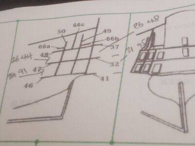
 Check the angles and distances between parts 37, 32 & 41.

 Check the angles and distances between parts 37, 32 & 41.
- Joined
- Mar 12, 2021
- Messages
- 121
- Points
- 88

thanks Darivs
- Joined
- Mar 12, 2021
- Messages
- 121
- Points
- 88

I think my last post must have been confusing!
the distance between mounting points for 41 and 32 is 31.95mm and the distance between 32 and 37 is 26.48mm.
when items 46,47 and 48 are introduced into the notches in 49 and 50, the gap between 46 and 47 is 24.91mm and between 47 and 48 is 26.44mm.
the 47 and 48 to 32 and 37 is negligible but 46 and 47 to 41 and 32 is just over 7mm difference hence my earlier question. it has nothing to do with angles but seems to be an error in the manufacture.
Hope photo helps explain!!

I had trouble with that too. In fact, the decorative posts joining the galleries didn’t fit in a few instances, and I had to add extensions to them. They were so covered with bling nobody notices. I would suggest doing what Kurt advised. In fact, the 1:1 drawing might help by putting the parts against it to see where everything lines up. I didn’t use those drawings as much as I should have.
- Joined
- Mar 12, 2021
- Messages
- 121
- Points
- 88

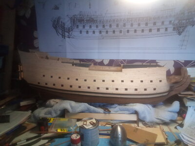
some progress has been made since my last photos. still have to tidy up gunports and cut out top row but before that im am going to attempt the dreaded galleries.
took Darivs advice and marked out correct angles with pencil lines. 8h pencil so nto visible in photos. looks like i willhave to detach the lowest gallery and adjust by a few mm's, then the hump, should be fun!

took Darivs advice and marked out correct angles with pencil lines. 8h pencil so nto visible in photos. looks like i willhave to detach the lowest gallery and adjust by a few mm's, then the hump, should be fun!


- Joined
- Mar 12, 2021
- Messages
- 121
- Points
- 88

- Joined
- Mar 12, 2021
- Messages
- 121
- Points
- 88

cheers Vic,
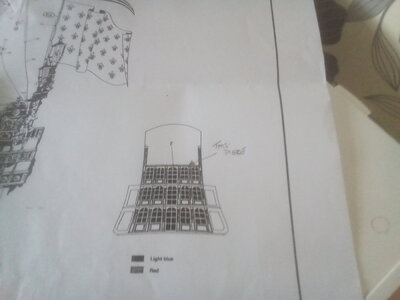
are those window frames painted gold? and what did you use as replacement "glass"? having followed the instructions and cut out the holes i now have nothing behind the window frames but instructions say to paint them blue!?!?!?
are those window frames painted gold? and what did you use as replacement "glass"? having followed the instructions and cut out the holes i now have nothing behind the window frames but instructions say to paint them blue!?!?!?
I painted the frames gold. I found some patterned cloth and glued it to the back of the "glass" to make curtains.
- Joined
- Mar 12, 2021
- Messages
- 121
- Points
- 88

thanks for that Vic, off remnant hunting now. That should please the Mrs!!
Remnant? Antiques? Thrift shop?


