marine steam engines and boilers

Hello,

Thanks for the update,
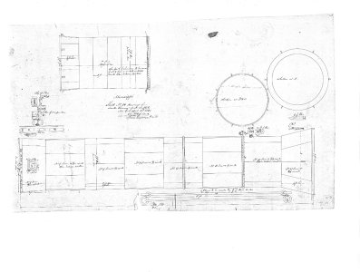
The information is 4 copper boilers were placed in pairs back-to-back with a common smoak stack.

It's a pity the diagrams are not a bit clearer to be able to read off any materials specified. It's clear that 3 fireboxes were in use per boiler, though not obvious (to me) what the horizontal tubes are doing.
It's just curiosity, as I said - in modelling terms you only need the casing - the external; visible bit. And I don't think that there was any period when boilers were not insulated with lagging, and a shell of some sort placed over that - which is the bit we see. Ships, railway engines, traction engines, and the good ole African Queen all had that arrangement.

Looks like a great project though - you'll be out of mischief for a couple of weeks at least...


Best
J
 
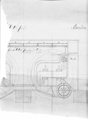
The drawing posted above is of a “Flue Boiler.” This is a very early type of fire tube boiler. The upper part of the large box contained the boiling water and the lower the furnaces. Below that was the ash pit. The hot gasses passed through a series of larger tubular or sometimes square flues before exiting up the stack. Above the box would be a chamber for collecting the steam and hopefully allowing any entrapped water droplets to drop back into the boiler.

Since the large flat surfaces of the box were pressurized by the boiling water
the boiler could only withstand very low pressures. A gage pressure of only 5psi was not uncommon. As I posted above, the early engines that these boilers fed generated most of their power from the vacuum provided by the condensing steam. These boilers were fed with salt water because the condensers worked by spraying seawater directly into the steam exiting the engine.

Copper has one useful property; it is an extremely good conductor of heat. It would have therefore been preferred for any surface required to transfer heat. Otherwise, wrought iron would have been the preferred choice due to its higher strength. Looking at the drawing, the box would not have been a heat transfer surface and some surfaces were in direct contact with the furnace where copper would not have had adequate strength at the high temperatures involved. I believe that the box would have been made from wrought iron.

The flues within the boiler were major heat transfer surfaces and coil dwell have been made from copper.

Roger
 
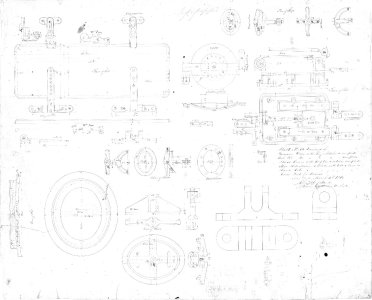
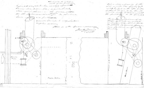
my idea at first was to build a diorama of the engine room. The problem i had was the fact i knew very little about steam engines. I did join steam engine forums but got no answers to my questions. Perhaps because no one knew much about early steam engines 1840s. I do have very detailed drawings for different parts of the engine but no drawing showing how the engine was actually built.
The one forum that really got into the engines is gone so after that i set the project aside.

i think an engine room diorama would make an interesting project and i have quilt a collection of 3d files for engine parts i am willing to share with anyone interested in picking up the project.

At one point someone wanted to build a working engine using compressed air. The problem with that was all the paers were modeled a seperate files and did not fit together so that ended that idea.


testing image size

the original drawings are difficult to read so here is a 300 resolution image that can be "save image as" and zoom way in.


Sht. 31. Furnace Door. Mar. 4, 1840..JPG
 
Last edited:
Back
Top