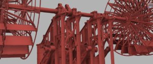
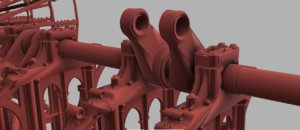
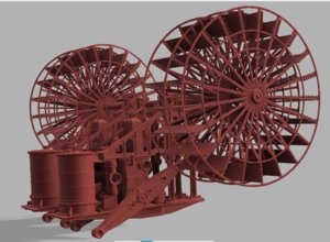
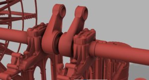
I love that idea, but wouldn't you need to be concerned with heat from friction distorting the resin parts?great video!
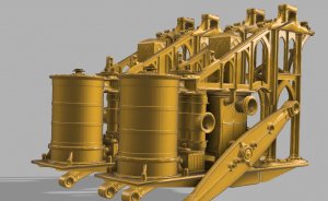
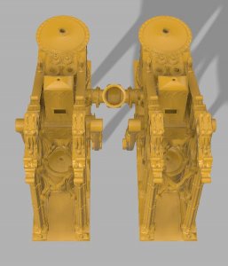
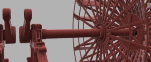
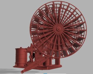
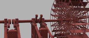
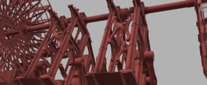
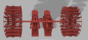
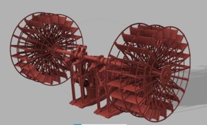
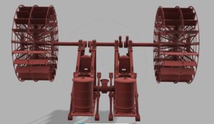
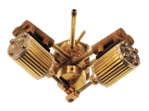
I was actually thinking about 3D printing this engine in a clear resin then running it on compressed air and pumping smoke through the engine to simulate steam and show how the engine would actually work.
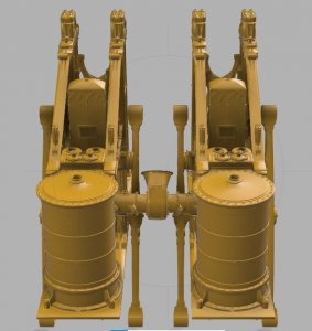
The Mississippi had two of these engines side by side so then I thought of a X section of the engine room under construction with one engine almost complete and the other being built my a team of little people with parts scattered all around the diorama.
-

Win a Free Custom Engraved Brass Coin!!!
As a way to introduce our brass coins to the community, we will raffle off a free coin during the month of August. Follow link ABOVE for instructions for entering.
-

PRE-ORDER SHIPS IN SCALE TODAY!
The beloved Ships in Scale Magazine is back and charting a new course for 2026!
Discover new skills, new techniques, and new inspirations in every issue.
NOTE THAT OUR FIRST ISSUE WILL BE JAN/FEB 2026
- Home
- Forums
- Books,Plans,Images,Museums & Reference Materials
- Other Reference Material: Web-Research, etc.
You are using an out of date browser. It may not display this or other websites correctly.
You should upgrade or use an alternative browser.
You should upgrade or use an alternative browser.
Marine steam engines and boilers
- Thread starter Dave Stevens (Lumberyard)
- Start date
- Watchers 18
-
- Tags
- marine steam engine
- Joined
- Dec 1, 2016
- Messages
- 6,390
- Points
- 728

I love that idea, but wouldn't you need to be concerned with heat from friction distorting the resin parts?
there are resins used for machine parts and high heat materials such as Delrin also wear resistant materials
so yes this project can be taken to the level of "engineering" and using bearings made from Nylon 3D printed metal high impact resins, high heat resins and so forth.
at this stage there are a few guys working as a team on this project.
there is research, cad drawings, 3D modeling, casting experts and resin printing experts. steam engineers, historians.
this engine was a one off one of a kind built for the first naval steam frigate in 1839. The navy decided to go with horizonal engines and this style was never built again. so this is a pieces of steam engine history. There is still a ways to go the boilers have to be modeled as well as all the piping and rods and shafts.
so if you want to join the topic over at the steam engine forum please do so.
I'll do so. I have a twin-cylinder marine steam engine that runs beautifully, but I have no boiler for it. The boilers I've seen for sale that are the correct size are over $600USD, and so I plan to build my own.I love that idea, but wouldn't you need to be concerned with heat from friction distorting the resin parts?
there are resins used for machine parts and high heat materials such as Delrin also wear resistant materials
so yes this project can be taken to the level of "engineering" and using bearings made from Nylon 3D printed metal high impact resins, high heat resins and so forth.
at this stage there are a few guys working as a team on this project.
there is research, cad drawings, 3D modeling, casting experts and resin printing experts. steam engineers, historians.
this engine was a one off one of a kind built for the first naval steam frigate in 1839. The navy decided to go with horizonal engines and this style was never built again. so this is a pieces of steam engine history. There is still a ways to go the boilers have to be modeled as well as all the piping and rods and shafts.
so if you want to join the topic over at the steam engine forum please do so.
- Joined
- Dec 1, 2016
- Messages
- 6,390
- Points
- 728

- Joined
- Dec 1, 2016
- Messages
- 6,390
- Points
- 728

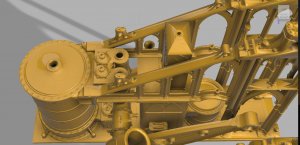
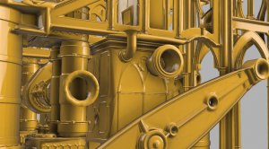
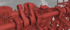
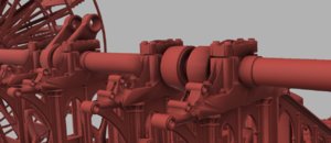
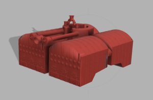
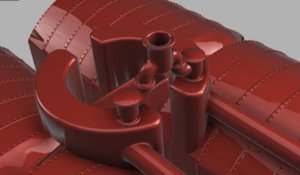
for anyone interested in the CAD design stages before 3D modeling there is a connection between the t column on the valve box and in inlet on the side of the condenser. you can see on the 3D model the 2 open ends. On the condenser the connection is called a gland and stuffing box. The elbow pipe is not bolted to this connection because when the pipes get hot they expand and contract. if everything were bolted together this would rip the engine apart. so connections are made so the pipes and connections slide into one another.
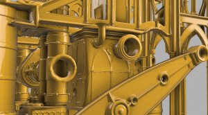
so as I do the CAD design work I have to line everything up and make sure everything will fit, I have to be thinking X,Y,Z
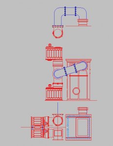
then I have to consider how it all fits into the engine and make sure pipes clear any moving parts like the lever arm
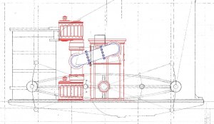

so as I do the CAD design work I have to line everything up and make sure everything will fit, I have to be thinking X,Y,Z

then I have to consider how it all fits into the engine and make sure pipes clear any moving parts like the lever arm

- Joined
- Dec 1, 2016
- Messages
- 6,390
- Points
- 728

- Joined
- Dec 1, 2016
- Messages
- 6,390
- Points
- 728

- Joined
- Dec 1, 2016
- Messages
- 6,390
- Points
- 728

one of these days I just might start to actually build the model every timber every nut and every bolt.
first I have to 3D model the hull, assemble the engines and boilers and all the piping.
it would make one heck of a X section model of the engine room.
right now I can't afford the cost to print the engine parts.
first I have to 3D model the hull, assemble the engines and boilers and all the piping.
it would make one heck of a X section model of the engine room.
right now I can't afford the cost to print the engine parts.
- Joined
- Dec 1, 2016
- Messages
- 6,390
- Points
- 728

- Joined
- Dec 1, 2016
- Messages
- 6,390
- Points
- 728

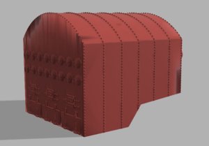
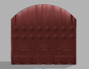
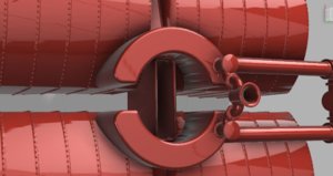
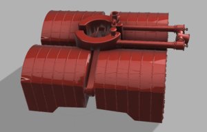
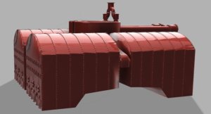
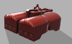
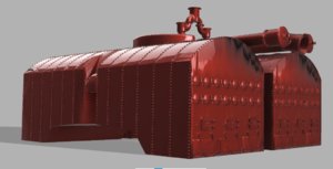
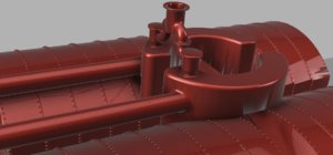
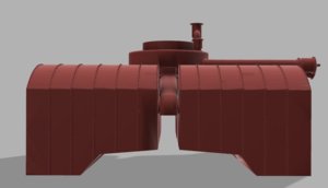
the boiler setup the real boilers were built of copper plates all riveted together. The assembly on the top is called the steam chamber below is the fire box and water. When the water turns to steam in rises into the chamber and out the pipes to the engine. A safety valve sits in the top and rises up through the decks and out along the stack just incase to much pressure builds up. that has not been modeled yet


Thought those interested in steam-driven model warships might enjoy this. This is a 1:48 model of the CSA Virginia II, built by my friend Jeff Sparksworthy. It gives you a glimpse of just how complex an operational steam-driven scale warship can be.
Last edited:
Great work Dave! Those support frames were a work of art! Like metal architecture!and the build goes on here is an update on 3D modeling of the engines of the Mississippi
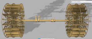
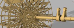
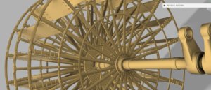
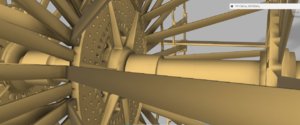
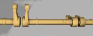
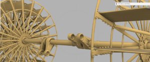
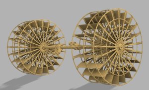
View attachment 124035View attachment 124036View attachment 124037View attachment 124038View attachment 124039View attachment 124040View attachment 124041View attachment 124042View attachment 124043View attachment 124044View attachment 124045View attachment 124046View attachment 124047
- Joined
- Dec 1, 2016
- Messages
- 6,390
- Points
- 728

- Joined
- Dec 14, 2021
- Messages
- 351
- Points
- 238

Really interesting build, Dave, could you give a link to that forum please.if you want to join the topic over at the steam engine forum please do so.
- Joined
- Sep 14, 2020
- Messages
- 152
- Points
- 88

Wow, I wish that I had seen this build a couple of years ago, I had was doing research on confederate blockade runners this being an intriguing part of my research. Almost makes me wanting to continuing
- Joined
- Jun 29, 2024
- Messages
- 1,524
- Points
- 438

Forum members interested in steam power might be interested to know that two examples of marine steam power plants that are open to visitors exist in the “Twin Ports” of Duluth, MN and Superior, WI.
The first is on board the whaleback steamship SS Meteor marooned in a Land berth at Superior, WI. It is an intact example of the scotch boiler/triple expansion marine engineering plant that powered the world’s merchant shipping prior to widespread adoption of steam turbine or diesel propulsion. The engine is original to the vessel (1896), the scotch marine boilers date from 1913. The piping systems including crosshead driven pumps and jet condenser are all there for those interested.
The second is aboard the SS William A. Irwin afloat in a permanent berth on the Duluth side of the harbor. Dating from the 1930’s it is a cross compounded steam turbine plant with watertube boilers; the final evolution of marine steam power (excepting some very high pressure US Navy applications in the 1960’s).
Both ships are open to visitors in the summer months. Unfortunately. We’re a bit out of the way but USA Midwesterners heading north for a Boundary Waters canoe trip or northwoods cabin vacation who are interested in marine steam technology will find visiting these museum ships worthwhile.
Roger
- Joined
- Sep 8, 2024
- Messages
- 203
- Points
- 88

Or more likely, there is no requirement for material in the centre of the column, and NOT having it full of cast iron is both cheaper and lighter. The minor additional complexity of providing a core for the casting would be trivial in comparison to the cost of the metal saved.The columns are hollow so either a pipe runs up the column or the column is being used as a pipe line.
And bear in mind that whilst modern drawing technology is an improvement in many respects, the discipline and constraints of working on a 2D drawing board is a first class way of understanding and appreciating the components of a design. If manipulating the drawing tools takes over brain space from the designing the design suffers.
Seeing these drawings makes you appreciate the victorian era and early c20 though - offices full of drawing boards and slide rules and the men who used them. Equally, the boat builders (then and now) who did so much work without detailed plans. How many sailors died because 'we' just guessed at the best / cheapest frame spacings?
j
- Joined
- Jun 29, 2024
- Messages
- 1,524
- Points
- 438

Throughout the Nineteenth century, there was a debate regarding the dual properties of steam; its ability to transmit pressure and its expansion properties. This resulted in two very different trpes of steam propulsion systems.
Low pressure systems followed James Watt’s principles. Steam slightly above atmospheric pressure expanded in a large cylinder before passing into a condenser resulting in a vacuum. Most of the work performed by the engine was, therefore, due to atmospheric pressure.
High pressure engines used higher pressure steam pushing against the piston. Steam was then exhausted directly to atmosphere.
Eventually these ideas were combined, resulting in high pressure condensing engines. The debate involved the idea of “cutoff.” How should the engine’s valves be adjusted to admit the right amount of steam balancing its initial push due to pressure vs its elastic expansion. There were “short cutoff” men and “long cutoff” men. Benjamin Franklin Isherwood, the US Navy’s chief marine engineer was a long cutoff man. As such, he was viciously attacked by the Navy’s Admiral David Dixon Porter, a short cutoff man. Fortunately for US History, Isherwood prevailed as short cutoff power plants proved to be underpowered. Isherwood’s long cutoff plants propelled the Navy’s ships that fought the Civil War.
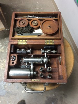
Eventually a device known as a steam engine indicator was developed to provide the information necessary to determine the ideal valve cutoff. This provided a graphic Pressure-Volume diagram of steam within the engine cylinder. These indicators are interesting examples of steam engine technology. Here is one in my collection from a Great Lakes Steamship:

Last edited:
- Joined
- Sep 8, 2024
- Messages
- 203
- Points
- 88

Can I just check - "real boilers were built of copper plates all riveted together."the boiler setup the real boilers were built of copper plates all riveted together. The assembly on the top is called the steam chamber below is the fire box and water. When the water turns to steam in rises into the chamber and out the pipes to the engine. A safety valve sits in the top and rises up through the decks and out along the stack just incase to much pressure builds up. that has not been modeled yet
is what we are seeing in the photos the boiler or the boiler casing? It seems to me that the outer shell in the pictures is a casing, containing lagging, and inside that the actual pressurised vessel containing steam, water, and fire tubes or flues.
The sting would be iron surely - cheaper than copper, and able to be cast around the firebox and for the firebox hinges.
As I say - just enquiring...
Jim
- Joined
- Dec 1, 2016
- Messages
- 6,390
- Points
- 728

Can I just check - "real boilers were built of copper plates all riveted together."
is what we are seeing in the photos the boiler or the boiler casing? It seems to me that the outer shell in the pictures is a casing, containing lagging, and inside that the actual pressurised vessel containing steam, water, and fire tubes or flues.
The sting would be iron surely - cheaper than copper, and able to be cast around the firebox and for the firebox hinges.
As I say - just enquiring...
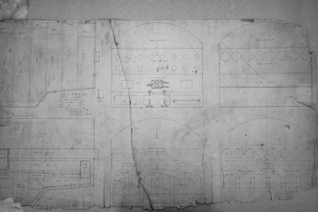
finding information on how the boilers were built is extremely rare. The information is 4 copper boilers were placed in pairs back-to-back with a common smoak stack. The weight of the boilers and funnel was 300 tons. New iron boilers were installed in 1856.
This is the original drawing for the boilers


