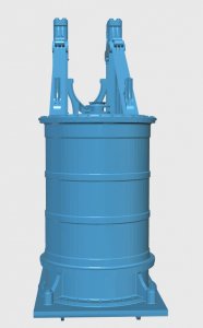
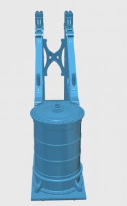
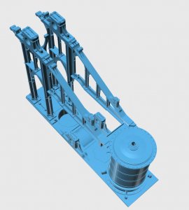
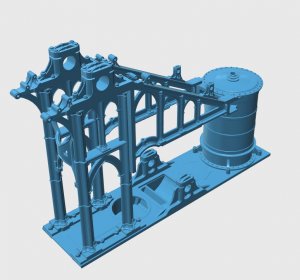
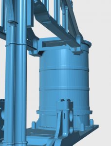
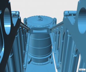
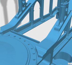
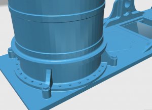
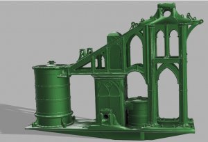
marine steam engines and boilers

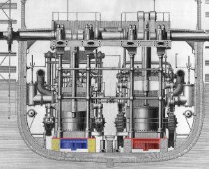
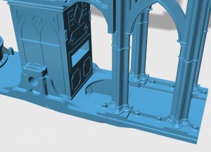
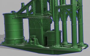
go back and look at the bottom of the bed plate, notice those fins running along the long side of the plate. Those are there to add strength to the plate and to wedge the engine so it can not move sideways.

the plate (red) sits on large wooden beams (yellow) along the side and the water well (blue) sits between these beans

bed plate mounting.jpg
 
WOW DAVE, WELCOME BACK, FANTASTIC, WHAT A INOVATOR, IMPRESIVE that you went to different people for EXPERT ADVICE, KEEP IT GOING MY FRIEND and MENTOR. Don
 
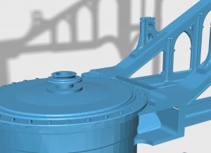
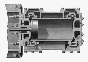
progress report on building the steam engine. The main cylinder is done and mounted into the engine.

piece by piece bolt by bolt the old steam engine is being re engineered

E cylinder1.JPGE cylinder2.JPGE cylinder3.JPGE cylinder4.JPGE cylinder5.JPGE cylinder6.JPGE cylinder7.JPGE cylinder8.JPG
 

Attachments

  • E cylinder9.JPG
    E cylinder9.JPG
    93.9 KB · Views: 2
  • E cylinder10.JPG
    E cylinder10.JPG
    80.9 KB · Views: 3
  • E cylinder11.JPG
    E cylinder11.JPG
    60.5 KB · Views: 4
  • E cylinder12.JPG
    E cylinder12.JPG
    54.1 KB · Views: 3
I was rethinking the project my first idea was to build a plank on frame hull but then thought hum that will hide all the finer details of the engine and boiler.

then I thought just a cross section of the engine room but that leaves out a lot of the ship.

Right now the problem is I have a lot of parts to this engine and little knowledge how it goes together. SO! why not a diorama of the ship under construction with a crew of little people doing the work? the engines can be under construction with pieces and parts laying out.

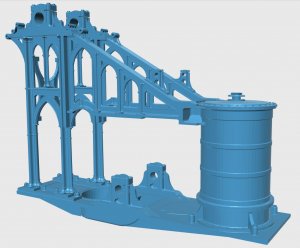
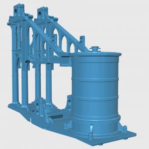
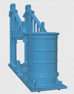
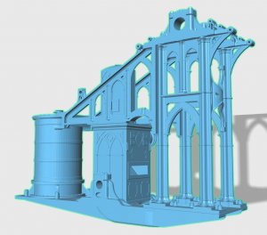
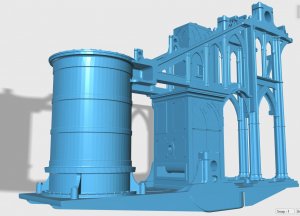
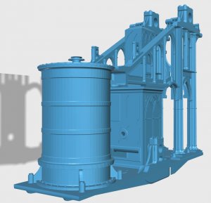
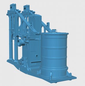
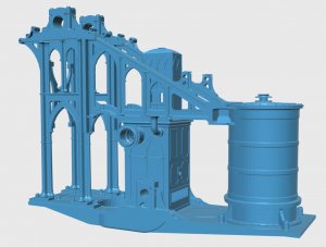
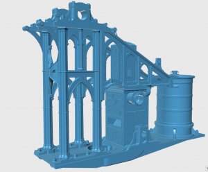
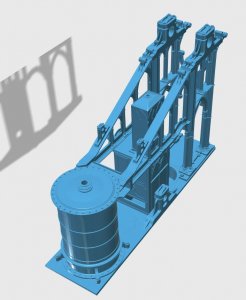
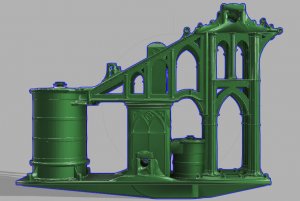
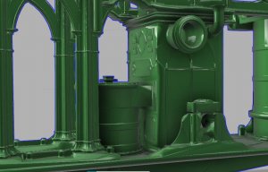
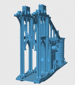
well one thing lead to another and if it is to be a diorama in a shipyard how were these engine parts moved? just the frames were 22 tons each and the bed plate another 10 tons. These frames as you can see in the 3D model had to be stood up and bolted to the bed plate. Did shipyards in 1830 have cranes and a gantry system? or was all this done by hand with ropes and pullies?

it is engineering logic the keel, floors and floor timbers were set in place and the engine built on it rather than the hull built and the engine lifted up and into the hull. so the hull was built around the engines.

if this is a steam ship were there steam cranes?

monolithic structures go way back in time and moving huge stones was not a problem back then. Building a steam engine with parts weighting 22 tons seems easy it was done all the time but how?
 
sharing of information really helps this hobby to grow
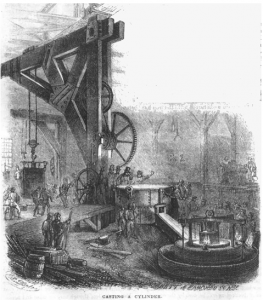
check out the crane in this foundry they are casting the cylinder which Mohamed just finished modeling.

casting cylinder.PNG
 
I am searching for illustrations or drawings of cranes, derricks, shearleg systems and gantry that might of been used in a shipyard of 1840.

a crane would have to swing to the side and pick up a part then swing it over the hull to be placed. This requires a slewing platform. how were cranes built in 1840 is the question.
 
The Fairbairn Crane Patent is from 1850.....
 
and now for an up date on modeling the engine
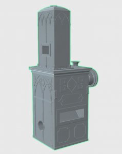
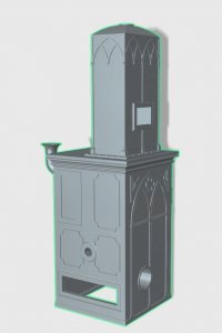
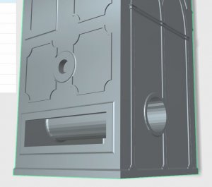
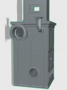
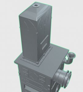
Mohamed finished modeling the condenser and the cooling tower. what this part of the engine does is the steam exhausted from the cylinder goes into the condenser where it comes in contact with pipes that circulates cold water and the steam condenses back into water. This water is then pumped back to the boilers.

there is a hole in 2 sides of the condenser with a pipe that runs from side to side. This lines up with the blocks and the lever shaft runs from block to block

condenserm1.JPGcondenserm2.JPGcondenserm3.JPGcondenserm4.JPGcondenserm5.JPGcondenserm6.JPGcondenserm7.JPGcondenserm8.JPGcondenserm9.JPGcondenserm10.JPG
 
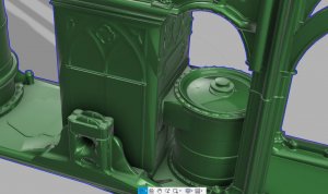
as each part is drawn in CAD and 3d modelied it is then fit into the engine. The condenser sits right above the opening in the bed plate which goes to the water well below the bed plate. As the water collects in the cooling well it is pumped back to the boilers.

condenser a1.JPGcondenser a2.JPGcondenser a3.JPGcondenser a4.JPGcondenser a5.JPGcondenser a6.JPGcondenser a7.JPGcondenser a8.JPGcondenser a9.JPGcondenser a10.JPGcondenser a11.JPGcondenser a12.JPG
 
the process of building the engine for the cross section of the Mississippi model is slow going, the biggest problem is the research. Most of the emails sent get NO reply and the others get huh I don't know.

back years ago a friend of mine from the old ship modeling club we use to have at the museum once told me. "if you request help and research information and you get no replies or no one seems to know than take a wild guess" if no one knows no one can prove you wrong.
The next part of the engine is the inlet and outlet of the steam from the main cylinder. after months of sending out emails I got nothing.

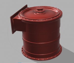
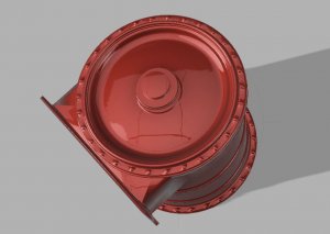
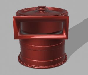
anyhow I do change up the rendering just for the heck of it so here is the air pump painted a gloss red

819928199381994
 
here are some of the books in my collection on steam. The books are quite useful on how steam engines work and how they are built

I can ask Author if he would upload the PDF files on the Navy Board site so you can look at the books

View attachment 49050View attachment 49051View attachment 49052View attachment 49053View attachment 49054View attachment 49055View attachment 49056View attachment 49057View attachment 49058View attachment 49059View attachment 49060View attachment 49061
 
Hello Dave, I have read through your postings many times in order to get more information about the things that are turning around in my mind.
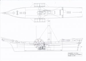
A few weeks ago I was lucky enough to get my hands into very beautifully drawn drawings of a steam ship Ilmarinen, which was the first steam driven ship in Finland. That ship was a side wheeler, built in 1833 and had an interesrting side lever engine made in UK by the company Clark.
The boiler and engine are freely visible at the ship, which would make it a beautiful and interesting model. So when my present project is nearing completion, I have decided to build next this Ilmarinen in scale 1/24, which would be big enough to model also the boiler and engine with great accuracy.
The problem however is that I don't have enough information about the engine. You have shown on your previous postings that you have many books about early steam engines. I wonder if some of those books would describe better also the side lever engines, their construction and especially their function with the controlling mechanism? If yes, I would appreciate very much, if you could send that kind of information to me, as a personal message or what ever ways. Or advice me further, where to get the information I need.
My intention is to build the model powered not by steam, but with an electric motor, hidden so that it would look like it would be equipped with a working side lever engine. Also it would be very easy to build the boiler very accurately and hide inside it a smoke generator, so that the whole power train would look very realistic out.
I will include here also a drawing of the ship, where steam engine has been shown quite nicely but not with all the necessary smaller details.
lImarinen_1.jpglImarinen_1.jpg
 
these engines were actually custom built, one at a time because they were in a constant state of improving and changing as new ideas came to light.

then engine i am building was a one off one of a kind built for the US Navy they built just one ship with the engine. England and Germany were the leaders in steam engines. For me to collect information from Europe is difficult
as for books i collected a number of PDF files and i agree it would be a good idea if we can have a collection posted on the Navy Board Model site.
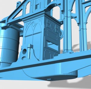
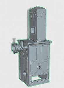
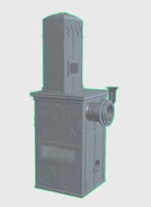
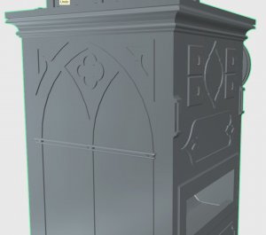
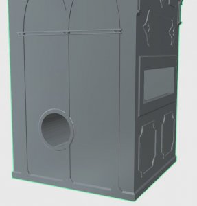
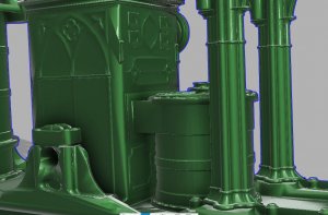
some of the engines were the gothic style with pillars and arches fancy moldings etc. some were more basic in structure. no fancy stuff just a working engine.


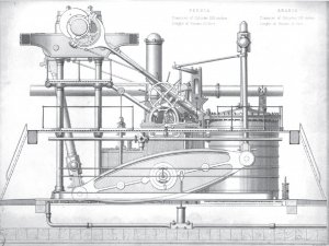
Engines_of_RMS_Arabia_and_RMS_Persia.jpg

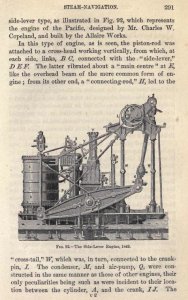
side lever drawing.JPG
 
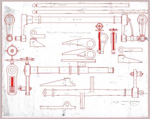
Thanks Dave for these two drawings. Basic working of these engines is clear for me, but the control of slide valve which controls steam in- and outlet of the cylinder seems to be very complicated with many levers and rods. It would be nice if you had some sort of drawing to explain the function of those.
 
Thanks Dave for these two drawings. Basic working of these engines is clear for me, but the control of slide valve which controls steam in- and outlet of the cylinder seems to be very complicated with many levers and rods. It would be nice if you had some sort of drawing to explain the function of those.

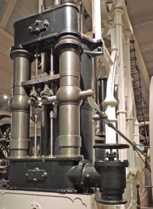
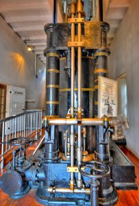
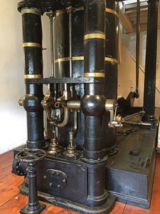
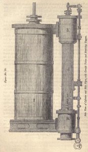
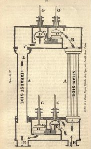
that is the part I am working on now and yes it is very complicated because there were several valve systems in use at the same time.v3.jpg1830 pump.jpgCD_Canal_Museum21_3.jpgv5.jpgv6.jpgPorter-Allen_cylinder_and_valves,_sectioned.jpgv7.JPG
 
Thanks again Dave. It seems that the engine you are working with is even much more complicated than this one cylinder engine that I try to understand. And luckily there is no need to fabricate all the filigrane parts to have it look like a working engine.
 
Back
Top