As Always Dave, Great thread, and a different but fantastic build, looking foreward to it . Don
-

Win a Free Custom Engraved Brass Coin!!!
As a way to introduce our brass coins to the community, we will raffle off a free coin during the month of August. Follow link ABOVE for instructions for entering.
-

PRE-ORDER SHIPS IN SCALE TODAY!
The beloved Ships in Scale Magazine is back and charting a new course for 2026!
Discover new skills, new techniques, and new inspirations in every issue.
NOTE THAT OUR FIRST ISSUE WILL BE JAN/FEB 2026
- Home
- Forums
- Books,Plans,Images,Museums & Reference Materials
- Other Reference Material: Web-Research, etc.
You are using an out of date browser. It may not display this or other websites correctly.
You should upgrade or use an alternative browser.
You should upgrade or use an alternative browser.
Marine steam engines and boilers
- Thread starter Dave Stevens (Lumberyard)
- Start date
- Watchers 18
-
- Tags
- marine steam engine
- Joined
- Dec 1, 2016
- Messages
- 6,390
- Points
- 728

- Joined
- Dec 1, 2016
- Messages
- 6,390
- Points
- 728

and after many hours of CAD drawing i am at this point of the build
from here the black, purple and blue parts will be drawn in detail then each will be 3d modeled. once the 3D model is created they will be placed into the frame and everything set on to the bed plate.
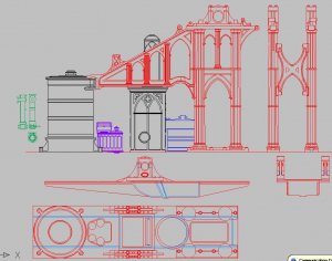
right now i am stumped with the green parts to the left i am not sure how these fit into the engine, my thought is they sit on the purple part and bolt onto the cylinder, exactly how is a mystery at this time.
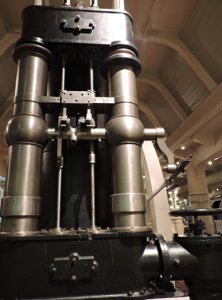
here are 2 photos of a gothic style engine with parts that sure look like the green parts in the drawing
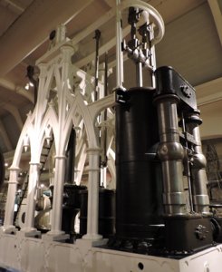
from here the black, purple and blue parts will be drawn in detail then each will be 3d modeled. once the 3D model is created they will be placed into the frame and everything set on to the bed plate.

right now i am stumped with the green parts to the left i am not sure how these fit into the engine, my thought is they sit on the purple part and bolt onto the cylinder, exactly how is a mystery at this time.
here are 2 photos of a gothic style engine with parts that sure look like the green parts in the drawing


- Joined
- Dec 1, 2016
- Messages
- 6,390
- Points
- 728

for those interested in 3D modeling and rendering
there is a new software by Autodesk called Fusion360 it is cloud based so you can upload your drawings and the Autodesk community can help you work through the learning process.
you can use any number of programs such as solidworks, Blender, sketchup, turbocad and others. You will start to see more and more 3D modeling and how it is applied to model building. It's great to see the models in 3D and how it all fits together and really cool animations. These people who do this have years and years of CAD design experience.
The new generation of model builders and engineers grew up with this stuff my grandson was using 3D modeling in high school 10th grade shop class.
AFTER 2 years of discussions with you Dave, I think it is finally here DUE TO YOU, interested to see how it helps us NOVICES AND INTERMEDIATE MODELERS, BRAVO DAVE. Don
- Joined
- Dec 1, 2016
- Messages
- 6,390
- Points
- 728

I was working with cad and 3d modeling going back years. back then it was extremely expensive to purchase the programs and well it is still expensive but getting affordable.
what is nice about Autodesk fusion360 if you are a hobbyist and do not intend on using the program in business or for profit Autodesk will give you the program FREE.
maybe the big companies are realizing the more the hobby guys work with these programs and learn them it will advance not only the hobby industry but also 3D animation, 3D printing. That was the big road block the cost of the programs.
you see it now with what Joe is doing he is showing you how the model looks before a single piece of wood is cut AND because of guys like Joe those CAD files can be used to create parts.
it still take 100s of hours to learn this and quite frankly not worth the time and money if you building just one model.
it still take 100s of hours to learn this and quite frankly not worth the time and money if you building just one model.
exactly,why spend 1000s of hours to make 3D parts virtually to build a model what takes years to finish in real,I think just waste of time what you can spend to build the model!!??
exactly,why spend 1000s of hours to make 3D parts virtually to build a model what takes years to finish in real,I think just waste of time what you can spend to build the model!!??
- Joined
- Dec 1, 2016
- Messages
- 6,390
- Points
- 728

exactly,why spend 1000s of hours to make 3D parts virtually to build a model what takes years to finish in real,I think just waste of time what you can spend to build the model!!??
Zoltan
at a hobby level for people building a model all the CAD work is useless it is the Rube Goldberg way of doing things, which is a machine intentionally designed to perform a simple task in an indirect and overcomplicated fashion.
to produce frame shapes of a hull with CAD you need a computer, then the software, then 100s of hours to learn CAD a plotter to print the drawings, a lot of hours drawing the hull. OR run the hull lines on a copy machine, cut out lifts, glue them together and shape the hull. once you have the shape slice it like a loaf of bread DONE!
you can spend over $1,000 buying a laser cutter, do all the CAD work and then cut out the frames OR a bottle of rubber cement and a scroll saw does just as will.
for the home DIY hobbyist all this 3D modeling, 3D printing, CAD designing is way overkill you don't need it. This does not make it easier it makes it harder because of the cost and learning curve.
BUT lets say this engine is part of a cross section kit of the Mississippi and you need to reproduce the parts over and over then that is a totally different story all this is necessary in the manufacturing process.
Zoly, I think you are missing the whole point of CAD and 3-D printing and instructions, I THINK THE POINT Dave and JOSEPH are makeing is not that the all modelers learn CAD, and 3-D printing but that those that are familar with the process so to say do the work THE BENIFIT FOR ALL MODELERS ESPECIALLY THE NOVICE AND INTERMEDIATE MODELERS are fantastic, it makes the builds understandable to us who are THE MAJORITY OF THE HOBBY TO BUILD BETTER AND QUICKER MODELS MORE TRUE TO THE INTENT, ZOLY WEATHER YOU LIKE IT OR NOT THIS IS THE FUTURE OF THIS GREAT HOBBY, the Chinesse, and the russians are starting to do this THEY RECONIZE THE VALUE OF THIS,as with everything FROM COMPUTERS TO TV started out EXPENSIVE WITH FLAWS, after some time THEY BECAME CHEAPER AND BETTER, ,,,MORE OF THIS FROM DAVE ANF JOSEPH PERSERVERE YOU GUYS ARE THE TRAILBLAZERS FOR WHAT IS TO COME, THE NAY SAYERS WILL SEE THE BENEFITS TO THE HOBBY WHEN IT STARTS TO BRING IN NEW PEOPLE WITH MORE NEW IDEAS, I still remember the NAYSAYERS WHEN LASER CUTTING CAME INTO BEING, IF YOU ARE SCRATCH BUILDING IT COULD BE AN INVALUBLE AIDE if you do not fight it,,,,,,so to DAVE AND JOSEPH AND ALL FOREWARD THINKING PEOPLE IN THE HOBBY MOVE ON TO BETTER NEWER THINGS, 3-D instructions are comming and PROGRESS WILL NOT BE STOPPED, BRAVO TO YOU ALL. Don
Hello Don,I did not miss the point as Dave outlined too,for a kit designer or manufacturer to create a visual 3D Cad model to show how the parts look like os comes together is ok if spend the time to draw up a 3D model,but for somebody who just build a model for himself to spend 1000s of hour to correct some minor errors on a planset what is already perfect to build from is a just waste of time considering how long takes to build the wodden model by itself.
AGRED ZOLY FOR AN INDIVIDUAL MODELER, BUT TO USE KIT OR SEMI KIT 3-D is what it is all about the cost to the DESIGNER could be spread over many sales or to offer it seperatly with a price, many inovative ways to acomplis this as you are a expert modeler maybe you do not need this aide BUT REMEMBER YOU ARE THE MINORITY BUT AN IMPORTANT PART OF THIS HOBBY THE NOVICE AND ESPECIALLY THE INTERMEDIATE MODELERS NEED THIS TO WANT TO PROGRESS TO MAYBE DOING A SCRATCH BUILD BUT THIS AIDE WILL KEEP THEM COMMING BACK FOR MORE BUILDS, REMEMBER NOT EVERYONE HAS THE SKILLS TO START OUT SCRATCH BUILDING, to most it is a learning process. Don
- Joined
- Jul 22, 2017
- Messages
- 331
- Points
- 268

I cannot help but think how many of these fabricators have had a significant loss of hearing after viewing all of those rivets. It is rather impressive if you think about how most of these ingenious ideas have been lost due to automation.
Raymond
- Joined
- Jul 22, 2017
- Messages
- 331
- Points
- 268

I can't help but think that these frames have a resemblance to cathedral arches. It is a shame that the natural beauty of this timeframe has all but disappeared.
Raymond
- Joined
- Jul 22, 2017
- Messages
- 331
- Points
- 268

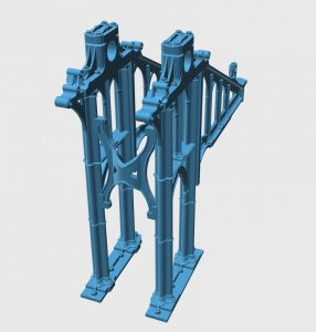
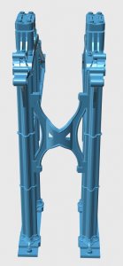
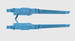
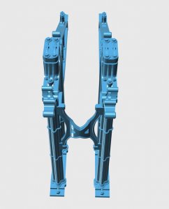
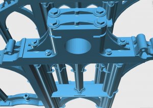
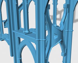
DANG!!! You really are an artist with the CAD. Is it really possible to execute the actual build in this manner? If so, will you show it on this forum as a means of keeping an eye out for it? Many thanks in advance, Raymond.OK here is the 3D model of the frames assembly now it is time to move on to the bedplate, cylinder, pump and condenserView attachment 68683View attachment 68684View attachment 68685View attachment 68686View attachment 68687View attachment 68688
- Joined
- Dec 1, 2016
- Messages
- 6,390
- Points
- 728

I can't help but think that these frames have a resemblance to cathedral arches. It is a shame that the natural beauty of this timeframe has all but disappeared.
Raymond
yupper Raymond thus the name cathedral style engines also called gothic style engines.
I can't help but think that these frames have a resemblance to cathedral arches. It is a shame that the natural beauty of this timeframe has all but disappeared.
Raymond
as the industrial revolution marched on the time and money of merging art, architecture and machines proved to time consuming, to expensive and unnecessary. Just like all the carvings on war ships slowly vanished and the ships became a weapon of war and beauty was left behind. This is a reason I selected this engine in this ship it is the one and only time this style of engine was used in a naval ship.
Looking at the 3D frames they were 20 feet long 18 feet tall and weight was 18 tons. These were cast as one piece and there were 4 of them used in the ship.
DANG!!! You really are an artist with the CAD. Is it really possible to execute the actual build in this manner? If so, will you show it on this forum as a means of keeping an eye out for it? Many thanks in advance, Raymond.
oh yes piece by piece as the engine is created it will be posted here. The biggest problem is understanding the original drawings. I do not have a back round in engineering so actually I am winging it using more guess work than actual knowledge of the subject. You would think just ask someone well that is not easy this was engine was built in 1839 and there are few people around that can build it.
So yes it is possible to execute the build as a 3D CAD model and take it one step more and actually make it work.
Hello Don,I did not miss the point as Dave outlined too, for a kit designer or manufacturer to create a visual 3D Cad model to show how the parts look like os comes together is ok if spend the time to draw up a 3D model, but for somebody who just build a model for himself to spend 1000s of hour to correct some minor errors on a plan set what is already perfect to build from is a just waste of time considering how long takes to build the wooden model by itself.
ya that's about right!
but even in the manufacturing and design, 3D models add more time and money to the project which will add to the cost of the kit.
Don said In time the cost of dong this will come down, not so because the cost is in the wages of the people who create the models. So really expect the cost to go up as the demand grows. Figure here in the US to hire a 3D artist to create a 3D ship as a building aid is in the thousands of $$ so that is the big reason it is not done. Your deep in the money pit before you even manufacture your first part.
Zoltan is on point for the average DIY hobby guy all this is way overkill
this is an interest and hobby unto itself and not to be considered an add on to make your model building easier or better.
Raymond
yupper Raymond thus the name cathedral style engines also called gothic style engines.
I can't help but think that these frames have a resemblance to cathedral arches. It is a shame that the natural beauty of this timeframe has all but disappeared.
Raymond
as the industrial revolution marched on the time and money of merging art, architecture and machines proved to time consuming, to expensive and unnecessary. Just like all the carvings on war ships slowly vanished and the ships became a weapon of war and beauty was left behind. This is a reason I selected this engine in this ship it is the one and only time this style of engine was used in a naval ship.
Looking at the 3D frames they were 20 feet long 18 feet tall and weight was 18 tons. These were cast as one piece and there were 4 of them used in the ship.
DANG!!! You really are an artist with the CAD. Is it really possible to execute the actual build in this manner? If so, will you show it on this forum as a means of keeping an eye out for it? Many thanks in advance, Raymond.
oh yes piece by piece as the engine is created it will be posted here. The biggest problem is understanding the original drawings. I do not have a back round in engineering so actually I am winging it using more guess work than actual knowledge of the subject. You would think just ask someone well that is not easy this was engine was built in 1839 and there are few people around that can build it.
So yes it is possible to execute the build as a 3D CAD model and take it one step more and actually make it work.
Hello Don,I did not miss the point as Dave outlined too, for a kit designer or manufacturer to create a visual 3D Cad model to show how the parts look like os comes together is ok if spend the time to draw up a 3D model, but for somebody who just build a model for himself to spend 1000s of hour to correct some minor errors on a plan set what is already perfect to build from is a just waste of time considering how long takes to build the wooden model by itself.
ya that's about right!
but even in the manufacturing and design, 3D models add more time and money to the project which will add to the cost of the kit.
Don said In time the cost of dong this will come down, not so because the cost is in the wages of the people who create the models. So really expect the cost to go up as the demand grows. Figure here in the US to hire a 3D artist to create a 3D ship as a building aid is in the thousands of $$ so that is the big reason it is not done. Your deep in the money pit before you even manufacture your first part.
Zoltan is on point for the average DIY hobby guy all this is way overkill
this is an interest and hobby unto itself and not to be considered an add on to make your model building easier or better.
- Joined
- Dec 1, 2016
- Messages
- 6,390
- Points
- 728

interesting video
- Joined
- Dec 1, 2016
- Messages
- 6,390
- Points
- 728

DANG!!! You really are an artist with the CAD. Is it really possible to execute the actual build in this manner? If so, will you show it on this forum as a means of keeping an eye out for it? Many thanks in advance, Raymond.
I am not the 3D artist, I am doing the research, design and CAD drawings but not the 3D modeling that is done by another member of this forum all the images of the 3D model are done by Mohamed a very talented industrial designer.

I am not the 3D artist, I am doing the research, design and CAD drawings but not the 3D modeling that is done by another member of this forum all the images of the 3D model are done by Mohamed a very talented industrial designer.

- Joined
- Dec 1, 2016
- Messages
- 6,390
- Points
- 728

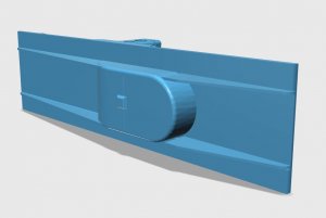
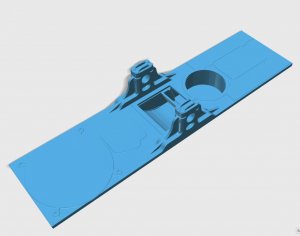
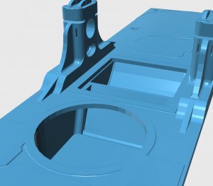
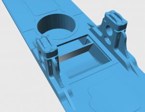
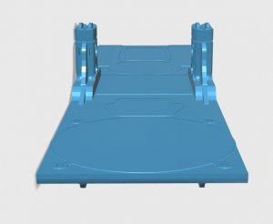
moving on with the engine project the bed plate that the engine sits on was modeled and here it is
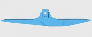
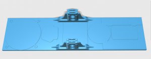
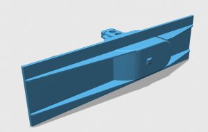
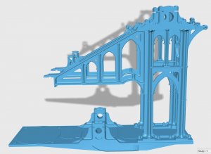
and here is the frame mounted on the bed plate
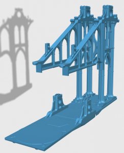
I do want to say there are experts in various fields backing me up on this project, it is truly an international project with people from Australia, Britain, Canada, Egypt and the US all getting involved.
how do I feel when someone emails me and says "dude that is so wrong" big mistake here. Well I tell you I feel delighted that anyone has taken such an interest to point out mistakes and taken the time to show me the right way. anyone looking at the model so far would never catch the error unless they are experts in the field of steam engines and engineering.


and here is the frame mounted on the bed plate


I do want to say there are experts in various fields backing me up on this project, it is truly an international project with people from Australia, Britain, Canada, Egypt and the US all getting involved.
how do I feel when someone emails me and says "dude that is so wrong" big mistake here. Well I tell you I feel delighted that anyone has taken such an interest to point out mistakes and taken the time to show me the right way. anyone looking at the model so far would never catch the error unless they are experts in the field of steam engines and engineering.
- Joined
- Dec 1, 2016
- Messages
- 6,390
- Points
- 728

Steam engines built for ocean travel can not use sea water to create steam so the system is closed and fresh clean water is used over and over. under the bedplate is the water well. The water in turned into steam in the boiler then it goes to the cylinder where it moves the piston and the lever arm, the steam is then exhausted from the cylinder into the condenser where it turns back into water and flows into the well under the bed plate, then from there it is pumped back to the boiler and the process is done over and over. Looking back at the 3D model the error comes to light, there is no open access into the well or out of it, the well is sealed. OOPS! my mistake when I drew the original CAD drawing Mohamed used to create the model.
so now it is back to the drawing board and taking a look at the original 1839 drawing
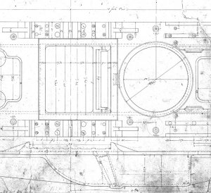
the area below the condenser and pump should be open like the yellow area
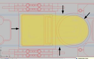
nope! still wrong because if I did that the green areas would be an open pit
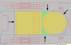
so with a little help from those watching what I do, the problem is solved. the blue areas are open to the well and the gray areas are ground smooth and the condenser and pumps are bolted to them.
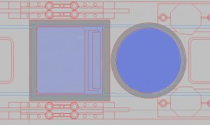
so now it is back to the drawing board and taking a look at the original 1839 drawing

the area below the condenser and pump should be open like the yellow area

nope! still wrong because if I did that the green areas would be an open pit

so with a little help from those watching what I do, the problem is solved. the blue areas are open to the well and the gray areas are ground smooth and the condenser and pumps are bolted to them.

Last edited:
- Joined
- Dec 1, 2016
- Messages
- 6,390
- Points
- 728


