-

Win a Free Custom Engraved Brass Coin!!!
As a way to introduce our brass coins to the community, we will raffle off a free coin during the month of August. Follow link ABOVE for instructions for entering.
-

PRE-ORDER SHIPS IN SCALE TODAY!
The beloved Ships in Scale Magazine is back and charting a new course for 2026!
Discover new skills, new techniques, and new inspirations in every issue.
NOTE THAT OUR FIRST ISSUE WILL BE JAN/FEB 2026
- Home
- Forums
- Books,Plans,Images,Museums & Reference Materials
- Other Reference Material: Web-Research, etc.
You are using an out of date browser. It may not display this or other websites correctly.
You should upgrade or use an alternative browser.
You should upgrade or use an alternative browser.
Marine steam engines and boilers
- Thread starter Dave Stevens (Lumberyard)
- Start date
- Watchers 18
-
- Tags
- marine steam engine
- Joined
- Dec 1, 2016
- Messages
- 6,390
- Points
- 728

I'm really enjoying this thread, and the great drawings!
thanks rob
here are a some links first two are a topic here about the US steam navy and the engine of the Cairo
the other two links are other forums with this same topic. I have 3 topics on different forums because each one has different members and different discussions going on.
thanks rob
here are a some links first two are a topic here about the US steam navy and the engine of the Cairo
the other two links are other forums with this same topic. I have 3 topics on different forums because each one has different members and different discussions going on.
steam
Steam This topic or should i say a rambling story of a time in history when imagination, technology and invention came at a rapid succession where engineering and the how to make it work were two steps behind the imaginative creations of men of the time. It is commonly believed a man named...
shipsofscale.com
ironclad gunboat CAIRO
I have notice models of cross sections of wooden sailing ship are basically all the same. you seen one you seen them all. With this in mind I though what if I could come up with something really different something that has not been done and would be challenging in design, in fabrication and in...
shipsofscale.com
Side Lever Engine
hello all this is a basic drawing of a side level steam engine 1840s used in the first naval steam powered war ship USS MISSISSIPPI because the drawing is very simple it lacks all the "working" details of how such an engine works. does anyone know if such an engine survives in a museum or...
www.smokstak.com
- Joined
- Dec 1, 2016
- Messages
- 6,390
- Points
- 728

- Joined
- Dec 1, 2016
- Messages
- 6,390
- Points
- 728

- Joined
- Dec 1, 2016
- Messages
- 6,390
- Points
- 728

- Joined
- Dec 1, 2016
- Messages
- 6,390
- Points
- 728

back in post 99 you can see examples of this part of the engine
- Joined
- Dec 1, 2016
- Messages
- 6,390
- Points
- 728

from another topic in another forum I also have on this engine
I found these diagrams while searching for images of Cornish engine valves. The poppet valves used on the engine that you are doing could have been similar to these even though your engine probably did not operate on the Cornish cycle. They call them double beat valves which I would call balanced valves. You should do more searching on Cornish pumping engines as there are still quite a few left in England. The 1812 engine at Crofton had Cornish valve gear installed in 1843.
https://commons.wikimedia.org/wiki/F...lves,_1866.jpg
https://navsbooks.wordpress.com/2016...lor-and-woolf/
https://commons.wikimedia.org/wiki/F...ine,_1904).jpg
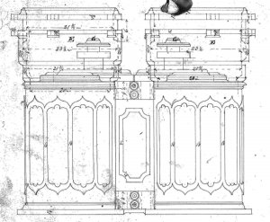
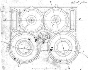
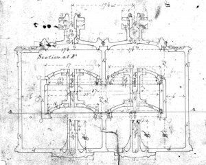
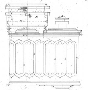
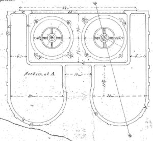
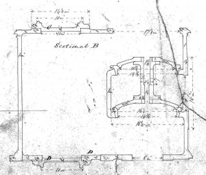
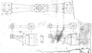
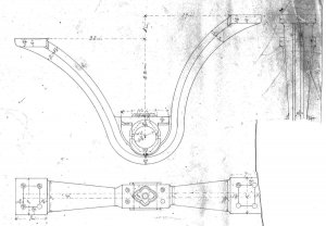
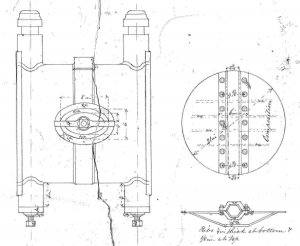
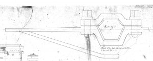
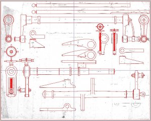
Ok, on the elevation of the valve chest there is an upper and lower clamp right in the middle, in the top view they have two 2-3/4" diameter holes. On the right side you have two lifters with 2-3/4" diameter holes. Looks like there are two lifter shafts with these mounted on them. I've got to get my head around the distance from the center of the lift shafts to the center of the valves and see if the lifters are the right length... one is shorter. The legend mentions cut-off. There is some other mechanism in play, the rock shaft lifts a toe on the vertical shaft, the arms attach to that and lift the valve, but what is the cut-off device? el's? I need to dig some. - JM
---------- Post added at 12:35:14 PM ---------- Previous post was at 12:21:49 PM ----------
Possibly:
http://americanhistory.si.edu/collec...ct/nmah_847097
I found these diagrams while searching for images of Cornish engine valves. The poppet valves used on the engine that you are doing could have been similar to these even though your engine probably did not operate on the Cornish cycle. They call them double beat valves which I would call balanced valves. You should do more searching on Cornish pumping engines as there are still quite a few left in England. The 1812 engine at Crofton had Cornish valve gear installed in 1843.
https://commons.wikimedia.org/wiki/F...lves,_1866.jpg
https://navsbooks.wordpress.com/2016...lor-and-woolf/
https://commons.wikimedia.org/wiki/F...ine,_1904).jpg
Ok, on the elevation of the valve chest there is an upper and lower clamp right in the middle, in the top view they have two 2-3/4" diameter holes. On the right side you have two lifters with 2-3/4" diameter holes. Looks like there are two lifter shafts with these mounted on them. I've got to get my head around the distance from the center of the lift shafts to the center of the valves and see if the lifters are the right length... one is shorter. The legend mentions cut-off. There is some other mechanism in play, the rock shaft lifts a toe on the vertical shaft, the arms attach to that and lift the valve, but what is the cut-off device?
 el's? I need to dig some. - JM
---------- Post added at 12:35:14 PM ---------- Previous post was at 12:21:49 PM ----------
Possibly:
http://americanhistory.si.edu/collec...ct/nmah_847097
- Joined
- Dec 1, 2016
- Messages
- 6,390
- Points
- 728

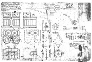
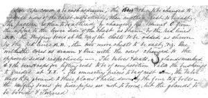
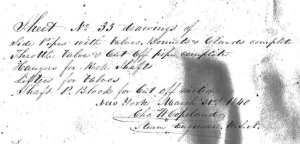
I tried to transcribe the instructions on the drawing and this is what I came up with
so even when you have the drawing right in front of you
you still have to figure out what the designer is talking about
Side pipe chest to be each as drawn, the ???? th?? To be changed to opposite sides of the chest respectively, then another chesty to be ??? The pattern is then to be altered by changing the bonnet C from the upper to the lower side of the chest as shown by the red lines D,D the stuffing boxes at the top of the chests to be added as shown by the red lines E,E then two more chests to be eas?? ??? one with the cores as drawn and one with the cores changed to the cores the opposite sides respectively the valves and seats ????? marked G and the boxes and caps for lifting rods to be of composition and also the bushings to guides at I,I the connecting pieces to be of cast iron, the valves seats to be ground to their place and held down by the four top bolts the stuffing boxes for side pipes are not to be boxed , ??? the glands to be boxed and turned
Sheet no. 33 drawings with side pipes and valves and cut off pipe complete hangers for rod shafts lifters for valves shaft P block for cut off motion
- Joined
- Dec 1, 2016
- Messages
- 6,390
- Points
- 728

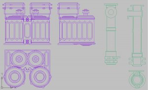
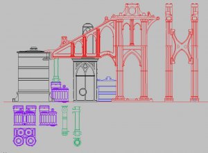
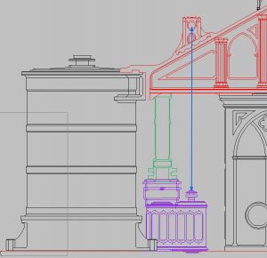
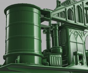
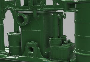
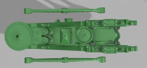
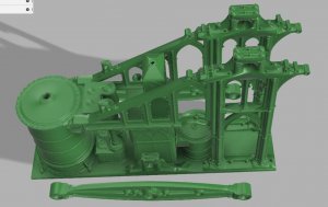
there is just about no interest in marine steam engines here on this forum or the 3d modeling of one so all the step by step modeling and model engineering is being done on another forum.
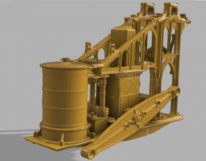
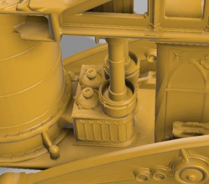
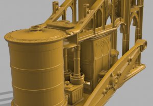
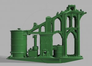
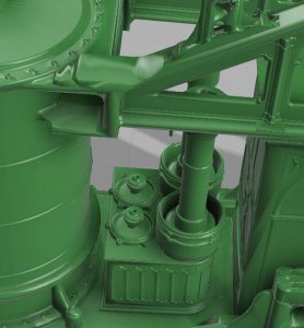
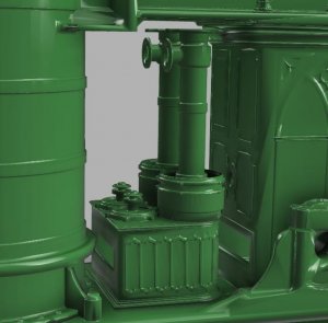
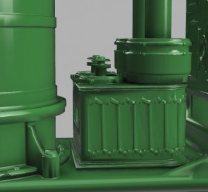
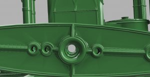
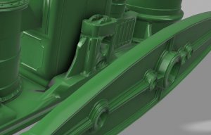
however here are some results of the work being done
as work proceeds the engine is rendered in different colors to separate the different stages of design work.
however here are some results of the work being done
as work proceeds the engine is rendered in different colors to separate the different stages of design work.
Last edited:
- Joined
- Dec 1, 2016
- Messages
- 6,390
- Points
- 728

once the modeling of the engine is complete there will be the building of the ship as a diorama but that is a ways off yet.
Hello Dave. At least I am very interested about your work. I have been waiting for a new update for a long time. Could you inform in which forum you are issuing your work so that I could go there and follow your postings.
I am asking this because I am just starting a new project, where my intention is to build a working side lever engine to power the paddle wheels of the model.
In fact you might be also interested about my blog where I have built a working two cylinder marine steam engine: https://shipsofscale.com/sosforums/...launch-built-in-1877-in-warkaus-finland.3126/
Last edited:
Stunning work! Will this be a working steam engine?there is just about no interest in marine steam engines here on this forum or the 3d modeling of one so all the step by step modeling and model engineering is being done on another forum.
however here are some results of the work being done
as work proceeds the engine is rendered in different colors to separate the different stages of design work.
Same here: Which forum has the most discussion?Hello Dave. At least I am very interested about your work. I have been waiting for a new update for a long time. Could you inform in which forum you are issuing your work so that I could go there and follow your postings.
I am asking this because I am just starting a new project, where my intention is to build a working side lever engine to power the paddle wheels of the model.
- Joined
- Dec 1, 2016
- Messages
- 6,390
- Points
- 728

Gothic Style US Navy "Mississippi" Ship - 1839 - (Side Beam Engine) (for first U.S. naval steam frigate)
I have been working on the design and building of this engine, the engine was used in the first naval steam frigate Mississippi. The model is based on the original drawings from the National Archives. the engine was built by this company
classicsteamengineering.com
oh my I did not realize anyone had an interest in the engine above is a link to the public forum however you may have to join the forum to see the larger images. also there is a lot of information between the people involved in the above engine going on in a private discussion. So if you want to join in the team working on this engine go to the link.
- Joined
- Dec 1, 2016
- Messages
- 6,390
- Points
- 728

what I am building is a hollow dummy engine which will be used in a diorama of the building of the steam frigate Mississippi. This will be in 3/8 scale and will result in a hull 7 feet long. At this scale every nut and bolt will be included in the engine and the boilers.
now there is an interest in taking the work being done in the design work and there is talk of castings for a working model. This step is a bit above what I am doing and falls into model engineering category.
People interested in model engineering and steam power check out the other forum.
now there is an interest in taking the work being done in the design work and there is talk of castings for a working model. This step is a bit above what I am doing and falls into model engineering category.
People interested in model engineering and steam power check out the other forum.
I shot this video of a model steam engine display at the Miniature Craftsmanship Museum in Carlsbad, California - just 20 minutes from my home. Hope you find it interesting. It's a large file, so be patient when downloading it: http://robwood.net/Miniature-Crafts...eam_Engine_Display_VID_20170204_131955281.mp4
- Joined
- Dec 1, 2016
- Messages
- 6,390
- Points
- 728

one great thing about this forum and other like minded forums they will link up and exchange information. some forums are very picky about posting links to other forums and topics. Lucky for us you can consider SOS forum a gateway to a massive amount of information world wide.
- Joined
- Dec 1, 2016
- Messages
- 6,390
- Points
- 728

great video!
I was actually thinking about 3D printing this engine in a clear resin then running it on compressed air and pumping smoke through the engine to simulate steam and show how the engine would actually work.
The Mississippi had two of these engines side by side so then I thought of a X section of the engine room under construction with one engine almost complete and the other being built my a team of little people with parts scattered all around the diorama.
- Joined
- Dec 1, 2016
- Messages
- 6,390
- Points
- 728

actually on another sister forum I do have the Alva B on the drawing board a early wooden steam tug boat.
Dave again magnificent, THE 3-D work is just amazing, your knowledge also and your ability to find and absorb things is amazing, are you planing a kit or is this for a muesem. Don PS X SECTION that i am talking about


