marine steam engines and boilers

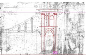
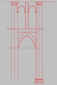
a progress report on the drawing I got the center section done. What I have to do is use the dimensions I can read and figure out what I can not read. All in all I come up with the correct size. I found you can not just start in one area and draw in all directions because you do not know what is distorted. Should I base measurements on one spot by the time I reach the other end of the frame I can be a foot off.

frame progress01.JPG
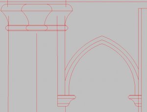
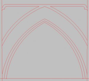
by turning off the first layer you can see what is going on what once was a blur of lines becomes sharp details. The 3D print process I plan on using has a high resolution and will faithfully reproduce the finest details, so I have to start with fine sharp details

frame progress02.JPGframe progress03.JPG

the molding on the top is 1 inch to scale that is .031 every arch, every arc and curve has to be Symmetrical everything is a balance from a given center. The joy of drafting is in the fine details and the following of architectural principals of the golden mean.

frame progress04.JPG
 
Last edited:
still working on the 3D model of the steam engine

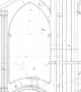
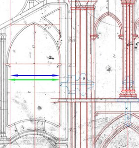
looking at the open arch the plan has 34 inches wide that is clear

off.JPG

when you actually measure the arch opening it is not 34 inches

the blue arrow is 34 inches the green arrow is the drawing, this is something I am running into as I redraw the engine and something I found when working with old admiralty drawings. You can not use them as scale accurate drawings. I found some as much as 10 feet difference. This is what is taking a log time I have to first read the given dimensions on the drawing, compare what is on the main drawing to the section drawings and component part drawings and fit everything together. When you look through all the drawings posted you can see the sections have letters and those same letters are on the main drawing so you know what goes where. Example at the bottom of the arch opening there is a (E) so I have to find section drawing E trace it, scale it and see if it fits into the main frame drawing.

offline.JPG

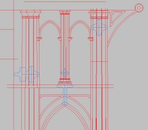
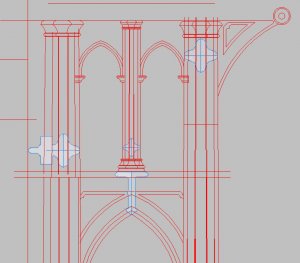
to accurately draw out the engine the blue drawings are X sections

x sections.JPG
x sectionsa.jpg

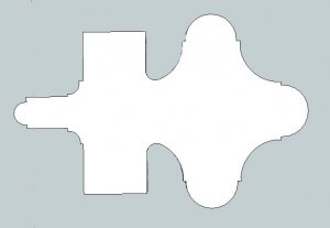
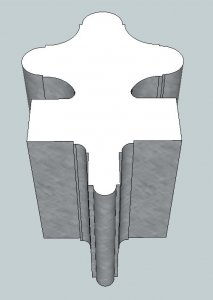
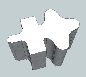
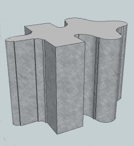
I can take these X sections and create 3D objects of them here is section S

section S2.JPG
section S1.JPG
section S3.JPG
section S4.JPG
 
last night I took a look at the engine drawing and see if I can figure out what is going on

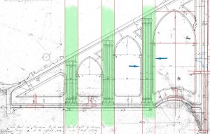
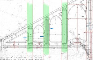
the green column areas are 11 inches that's what the measurement on the plans are. the archways between the columns from right to left the first one is 34 inches then 24 inches and finally far left is 20 inches according to what is marked on the plan.
the far right column is out of place the blue arrow in the 34 inch column has to move left, but where it is now is in the correct place 34 inches from the other side. On the left side it falls short of the archway side the blue arrow shows were it should be. Shifting the column the measurements on the plans will be wrong. In other words to just shift the first column to the left will make the 24 inch arch to narrow and the 34 inch arch to wide.

model engineering is just not a matter of gluing parts together it is planning and designing.


layout1a.jpg

I tried to shift all 3 columns to maintain the correct measurements of 34 inch arch, 11 inch column 24 arch, 11 inch column and a 20 inch arch and 11 inch column this is what happens, the right column set in place to the drawing the other 2 fall out of place. The question is are the measurements on the plans wrong OR is the drawing wrong?

layout2b.jpg
 
The thing is, this is the main frame of the engine and there are 4 of them. There are a lot of pieces and parts that bolt to these frames and in the end everything has to line up. If I am off 5 inches on the frame anywhere something down the line will not match up and the structure will not bolt together.

I notice from archaeological studies of ship wrecks the framing both of the hull and decks were not even. Frames would differ as much as 3 inches in size and spacing, deck beams were different as much as 2 to 3 inches. Now I get it! from the time the keel was set it was a constant "adjustments" of the structure.
Model ship building does not reflect actual ship building with every frame exactly the same size and spacing and everything milled and to exact sizes.
 
Last edited:
then there is this to deal with, ever try to read almost 200 year old plans? there are notes on the plans IF you can read them


text.JPG
 
As I research and draw the engine and boiler for the Mississippi I came to the conclusion I will have to research and study the steam engine before I can draw and build one. It stands to reason the more input I have the more information I can collect so I contacted the moderator on this forum as well as the administrator of another forum asking if I can link this topic on both forums.
There is no reason to build and maintain two separate topics It makes more sense to link them.

below is the link to the side lever steam engine while you are there might want to look about.

Forumspringlogo.jpg
http://www.modelboatmayhem.co.uk/forum/index.php/topic,61792.0.html
 
Last edited:
Steam engines and boilers operate on the same basic principals they are just modified to fit an application. So I figured lets take a walk about in a boiler graveyard and see what they look like.

A BOILER GRAVEYARD photographed by dave stevens

DSCN8296.JPGDSCN8297.JPGDSCN8298.JPGDSCN8299.JPGDSCN8300.JPGDSCN8301.JPGDSCN8302.JPGDSCN8295.JPG
 
Last edited:
after many hours with autocad I finally finished the frame drawing

frame1.JPG

the image is small so zooming in you can see the detail work

frame2.JPGframe3.JPG
 
like I said in the beginning there are 76 drawings this is just the first
to actually understand the drawings and the parts and how it all fits together I took a trip to the Henry Ford museum of industry and technology. There are a few steam engines on display so I figured I would take a look and see if I can get a general idea of how they work.

The engine in the Mississippi was a side lever engine of the gothic style. what we are looking at is a top lever engine of the Gothic style.
This is a prime example of the details of such an engine

DSCN7728.JPGDSCN7729.JPGDSCN7730.JPGDSCN7731.JPGDSCN7732.JPGDSCN7733.JPGDSCN7734.JPGDSCN7735.JPGDSCN7736.JPGDSCN7737.JPG
 
Back
Top