MarisStella Ragusian Carrack by Signet [COMPLETED BUILD]

Joined
Nov 17, 2021
Messages
839
Points
318

Location
Columbia, SC
I purchased this kit some time ago, but did not start until recently. The impetus and inspiration for getting this particular model was (surprise) Olha Batchvarov's wonderful topic and series of videos, posted here on ShipsOfScale.com. I didn't even care for this type of ship before drooling over her posts, photos and videos; I thought they were "cartoony" and didn't really look that way. But I grew to love the look as I admired her presentation.

So why am I posting a thread about building this model? I have none of Olya's skills or experience. The ship has also been well-covered here by Jack Aubrey, and in that other ship forum by GreatGalleons. Certainly I can't compete with those builds. This will be, after all, my first full ship model build in over 60 years (the last being a solid hull Xebec from Popular Mechanics Magazine), and my first, last and only planked hull over bulkhead model. Well, to be honest, I'm hoping to gain more from you great modelers who I hope will follow my build, with suggestions, comments and criticisms. Plus, I have a nasty habit of trying new things, many of which don't work out, and it might be fun to watch me dig myself out of the holes I dig along the line.

With that introduction, I'm sure you're all anxious to follow my build. I hope you will, and hope you will comment freely, as well as help answer the many questions already forming in my mind.

For any of you unfamiliar with this kit, I'll just post a pic of what I hope to accomplish over the next months and, probably, years:

1677387230087.png
 
I will first mention that I received the "updated" Ragusian Carrack kit. It included the additional brass photo-etched parts that Olha received after construction, but also several changes:

  • The plans have been re-done (just some small details). I'll discuss specifics as I go along, but one was to move the bowsprit off-center as I believe was done on some ships at this time.
  • Some (many?) parts are more accurately laser cut now, mostly the keel, stem and stern parts that make up the backbone of the ship and model. Olha had to remake hers, mine fit fine.
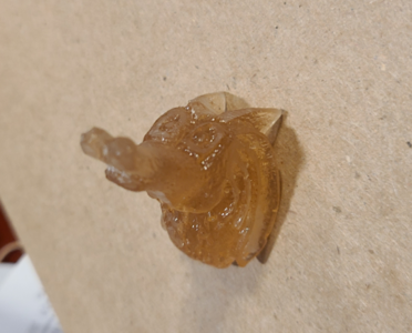
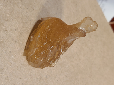
  • The figurehead is now furnished in a type of plastic, rather than having to be carved from 3 pieces of walnut. It's not an exact representation of the previous one (it lacks the long "horns" of the original), but can save a lot of work as well as frustration for those with limited carving experience. Here's a couple pics in its raw state:
1677387877877.png1677387892239.png
Olha called it a horse and felt it looked like her horse in the Urkraine. I see more of a sea horse. In any event, it is interesting and seems to suit the ship.

I began like all would of this model, laying out the keel and attached parts:
1677388096808.png
As you can see, the parts fit pretty well. The line etched in the near side of the parts is for carving a recess for the planking to go into the keel and its parts. I thought the line represented the /outside/ of the planking, so started carving there. After removing and fitting some bulkheads, I found that it represented the /inside/ of the planking, so had to make the groove wider and/or further towards the outside.

Rather than use a chisel and blades to carve the groove in the keel, I simply used my hobby table saw. It produced a straight kerf of roughly about 1.8mm, roughly the thickness of the planking, and since for almost the full length of the keel the planking meets the keel at almost a right angle, did a great job. I used a combination of saw cuts, chisels and blades to saw out the other grooves, much wider towards the stern where the planking blends smoothly to meet the keel and stern where the rudder mounts. This shows some of the cutouts for planks in this area, some of which could be done again on the table saw for accuracy:
1677388511264.png
Checking the fit using bits of planking:
1677388440232.png
I also added a bit of reinforcement since I had thinned this area considerably:
1677388579226.png
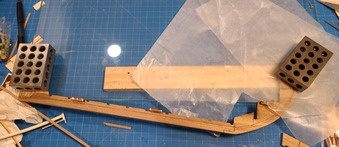
While I did use glass atop the plans for laying this out, I found the glue stuck to the glass making me concerned it would break when separating it. I later used was paper to prevent this. The glass does an excellent job of keeping everything very flat, though, along with weights, during gluing.

At first, I only glued the lower portion of the stem in place. I fully expect when handling this assembly, before and/or after adding the bulkheads, to carelessly catch an extending part and break something, probably the keel. I SO do not want this to happen, which is why I waited to add some parts, but realizing they were necessary to work with holes for the bowsprit, I added them after mast blocks were in place, preventing the whole frame from resting on the glass:
1677388817630.png
I'll be continuing probably tomorrow, as I have a backlog of photos over the last couple weeks (most of the time during which was taken in rebuilding a failed computer).
 
Signet I'm impressed once again. To my shame I have to admit that this type of ship never appealed to me either. However, I have changed my mind. I'll grab a chair and sit in the front row. Great project signet, first class.
 
Signet I'm impressed once again. To my shame I have to admit that this type of ship never appealed to me either. However, I have changed my mind. I'll grab a chair and sit in the front row. Great project signet, first class.
@Tobias, I have to disagree. I absolutely love the medieval cogs and carracks. The Maris Stella kits are on my (rather long) list for sure, but apparently Model Expo cornered the market here in the US.
 
Last edited:
1677388096808.png
@Signet,
Seeing this next to your glue bottle, this looks incredibly small. Is she as small as she looks? What is the scale and length of that keel?
 
Signet I'm impressed once again. To my shame I have to admit that this type of ship never appealed to me either. However, I have changed my mind. I'll grab a chair and sit in the front row. Great project signet, first class.
I hope you enjoy your seat. I saved the cushiest ones in the front row, so you may fall asleep, but glad you're with us!
 
@Signet,
Seeing this next to your glue bottle, this looks incredibly small. Is she as small as she looks? What is the scale and length of that keel?
I thought the same when looking at the keel. The keel itself is only about 14" long, but the ship builds to 77.5cm in length (30.5") which is a PERFECT fit for my 32" inside width bookcase. It is 1:59 scale and on the large side for a ship of its 16th century era. Stem to stern would have been about 115' and beam about 33'.
 
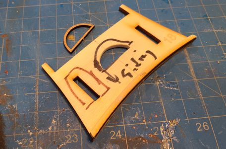
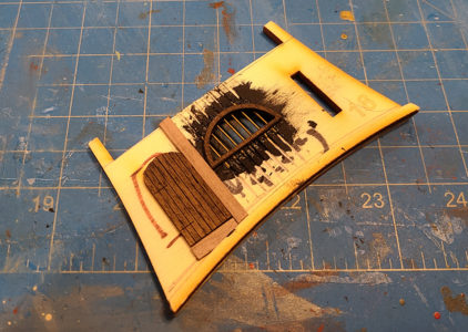
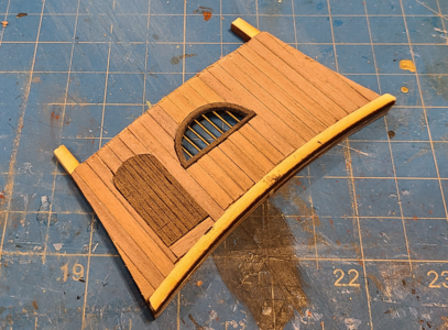
Continuing on, I wanted to get a feel for the color scheme for this model. It's a great kit, with everything visible in walnut, but that makes it kind of monochrome. At the least I wanted to darken some areas of the walnut (as others have done - not taking credit for the idea), and maybe lighten the deck as well. So I went ahead and assembled the smallest "finished" section I could find, which is partial bulkhead 18. This is at the end of the quarterdeck, has a door and a barred window, presumably through which the pilot would be able to look out of while operating the whipstaff which in turn moved the rudder for steering.

I laid the window outline and cut the opening to approximate the inside of the laser cut window:
1677436655794.png
I had previously marked "Siding" as a reminder on those bulkheads which required planks to be added before assembly.

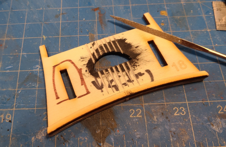
I placed evenly spaced lines, supposedly vertical to the ship axis, as a guide and filed 60 degree V-grooves to accept the rods (1/32" diameter brass wire):
1677436719126.png

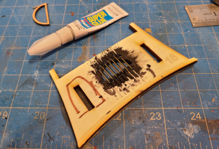
Then I painted black around the opening and glued the brass wires in place with super glue:
1677437184246.png

The window is then glued in place, and I set the spacing for the door, making sure it's vertical:
1677437000089.png
Both door and window have been lightly stained with a thinned mixture of Varathane Classic Water Based Wood Stain in Dark Bourbon. I usually use, and prefer, an oil based stain like Minwax, but for this project, I knew I'd be stained 1-2 parts at a time, and this way I can easily clean my brush in the bathroom without having solvents around.

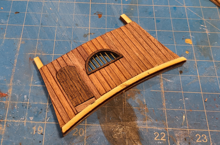
After all planks have been glued in place and outer edges sanded:
1677437435419.png
And after a quick coat of Minwax Wipe-On Poly Clear Satin:
1677437489899.png
Door hinges and handle will be added later.

BTW, some others building this kit elected to allow a plank-size gap between the bottom of the vertical plank and the deck plank supports, so the planks could be slid under when laid. I did the opposite, as I know I can have accurate square-cut deck planks to butt into the vertical siding. but was less confident in having an exact curved line properly meet the deck.

For this area, and perhaps with others, I elected to slightly bevel each plank to make them look individual. I find that perfectly smooth planks butted to each other and sanded can lose the individual look and blend together in some areas, look separate where color changes show it, and prefer this consistent look.

Yes, I realize the brass bars are not quite vertical. My pencil lines were. My filed grooves looked like they were. The bars seemed okay. But somehow they ended up tilted. I think it's a real shame that 16th century ship builders couldn't hire more competent carpenters, or elected to allow them their daily grog portion prior to the work day, don't you?
 
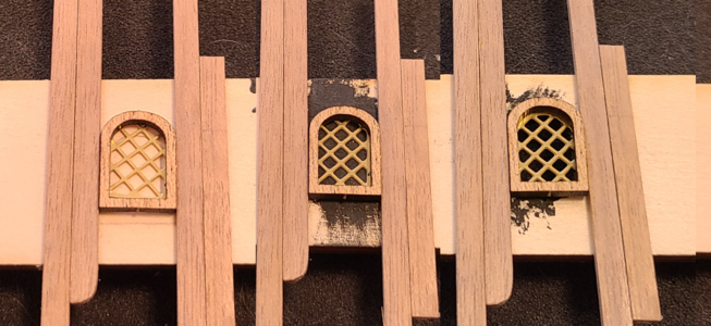
Oh, I forgot to post, but before making the above semi-finished wall, I experimented a bit with windows. Olha placed her windows flush at the back of the wall with the back of the planks, and cut out the openings because she lit the ship with many LEDs. Jack Aubrey placed his windows atop the siding and painted the are black behind them. I liked the more flush look, but have no intention to light the ship. so tried 3 methods:
1677438654093.png
The left window has nothing behind it, but could simulate a window with a drape or other colored material behind it, as Olha did in locations where openings were impossible. The center window simply has black paint behind it. The right window has been cut out behind. In this photo, you can see the difference between the black paint and no material, but to my eyes, as well as to my wife's recently cataract-removed eyes, the center window looks great, so that's the way I'm going. I can't run the planking continuously and cover with windows, but at least I don't have to make cutouts and the lack of ability to make cutouts does not change the appearance. Oh, and without the cutout, the window frame stands proud of the siding by an additional 0.5mm, so I think that looks good as well.
 
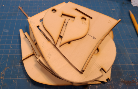
In the meantime, I removed and cleaned up the bulkheads
1677439719154.png
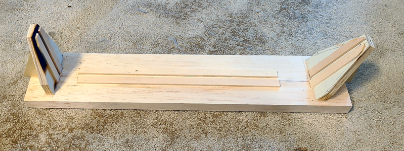
And made a "stand" that supports the model fairly well by its keel and its extensions
1677439765011.png
The large base piece is of balsa, and was supplied with the kit, while the rest was from scrap wood on hand.

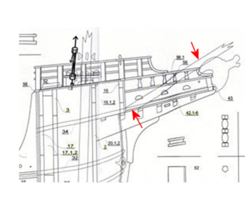
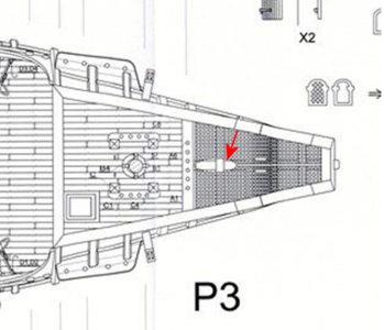
I'd been reading ahead, reading plans, diagrams, instructions and materials list, and looking at builds by others, and went on a fairly long and involved detour. (Some will no doubt call it a wild goose chase.) One of the biggest changes in the model and plans for the newer kit from the older one is the location of the bowsprit. The original plans (taken without permission from Jack Aubrey's excellent review and build) shows what appears to be a normal, centered location for the bowsprit:
1677440166605.png1677440212742.png
This clearly shows the bowsprit on-center of the ship, and for the model at least, ends in horizontal plate over the grating at the stem (not sure of the terminology). Olha clearly shows in her video how and where to install it:
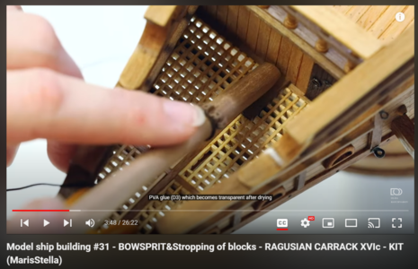
1677440501705.png

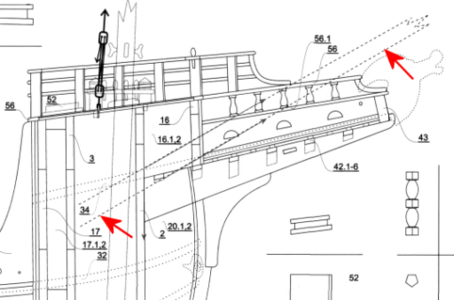
My new plans show something completely different, and at first I was shocked:
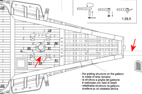
1677441113543.png1677441148394.png
The above clearly shows that the bowsprit extends further into the hull (as it should, for support), and has been offset to the starboard side in order to clear the foremast, which it sits beside. I've never noticed this on a ship, but it makes perfect sense, on a ship of this (smaller) size, where the mainmast is far forward. As this was a later modification of the plans, I'm sure it's intentional and is considered more accurate for the ship, so I need to do it. And it does make perfect sense to me. It's just that I've never noticed it before on a ship, and have to think it will look funny. And people will think I made a mistake. But since that's not unusual for me, I'll take a chance.

Naturally, the bowsprit now has to go /through/ bulkheads 16 and 2, at least, for proper support. I notice from the BM that the bowsprit is made of 10mm round walnut dowel, and proceed with the (incorrect) assumption that it will be 10mm diameter at its base and support, tapering to less at the tip.

So I look for bulkhead 16. AND CAN'T FIND IT! That stack of bulkheads has made it from the sheet, to being cut out, taken to the garage for sanding, back to my den for fitting to the keel assembly, and it's nowhere to be found. One of my bad habits is to work over a trash can, and many a time have had parts fall into it from my desk/workbench, later to be found after going through the plastic bag within. Plus at my age, I drop things all the time, and they bounce who knows where. But I can't find this anywhere. I checked the laser cut sheets thinking I missed it, and while still have them and I marked them with bulkhead numbers, that particular one isn't marked. I found out from Net pics or reviews it was located at the top of another bulkhead. So here I am thinking I lost it, and now have to make a new one.

I WAS able to make a new one. I used its location on the cutout sheet for the bottom width, the top and slots contour from nearby decks, the height from the side view plan, and was able to make a new one. Not having other scrap large enough, I cut out the center of bulkhead 3 (as Olha had done to make a "room" to light):
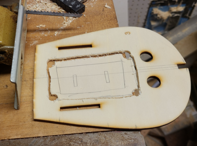
1677441942932.png

After cutting it and shaping it, I positioned it next to bulkhead 3 and located and drilled the slots for connecting parts:
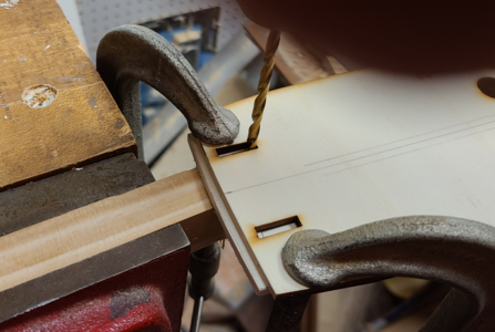
1677442044429.png

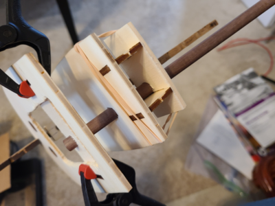
At this point, I located and drilled 10mm holes through the 2 bulkheads (10mm off of center, to allow for the 10mm foremast) and a scrap piece (for the 3rd) at the correct angle (about 30 degrees), glued bulkhead 3 to the frame assembly, temporarily located the other bulkheads and spacers, and fit the 10mm dowel bowsprit in place:
1677442325932.png

I felt real good about this, having lost a part, constructed a new part, then solved the problem of location and angle for proper support of the bowsprit.

Then it all went downhill: I FOUND THE LOST BULKHEAD #16!

1677442763971.png
So, why bad? I'd already made a new part, right? Well, a look at this part told me that the hold shown wasn't any 10mm. Closer to 8, actually. So I checked the drawing on the bowsprit. Yes, it's made of 10mm walnut dowel, alright, but the drawings show it more like 9mm or less at its largest. Oh, and it's not long enough to go through the first 2 bulkheads, let alone the 3rd one. And it seems that's the case on all the dowels: most are much larger than they end up being, even in their largest location.

Now, I'm sure all of you are laughing at how stupid I was to assume the included dowels were sized correctly, and only had to be tapered. But remember my first post: the last ship model I made was over 60 years ago! In my cross section models, the masts don't vary much, and start out the right size!

Okay, well not a catastrophe (although if I hadn't made a replacement bulkhead 16, I would have questioned all this earlier): I can use the new, correct bulkhead 16, and even modify bulkhead 2, if I add an extra piece on top with the smaller hole and allowing the bowsprit to reach it. But, this has really thrown a monkey wrench into my timing. I already am questioning how I'm going to taper the masts, spars and bowsprit properly. Now I have to reduce the diameters in some cases by over half at their maximum, over 2/3 at the minimum, and keep them round. So I'm thinking lathe (not for long) or other sanding methods.

The main thing is: I feel I have to actually construct the bowsprit at the final diameter, and preferably taper, before proceeding with the construction of the kit. If it varies in size, then my (new) holes will have to vary as well. And there are some problems with that:
  1. I really don't know how best to change dowel diameters by a good bit, as well as consistently taper them. I've been doing research, but I'm willing to bet I'll have problems.
  2. The included bowsprit really isn't long enough, even to make it to the second bulkhead, let alone the 3rd that I had planned. It needs to be on there sturdily. I really need a longer piece for it.
  3. I have to modify ALL dowels extensively, even though there are standard US dowel diameters (from HobbyLobby.com) that come much closer to the required diameters.
  4. I've been toying with substituting different materials for the masts in particular, and possibly spars as well. All walnut is a bit more monochrome than I really like. So:
On my Victory cross section, the masts are all light in color (beige or yellow ochre being the accepted norm) while the spars are black. That seems to be the accepted norm for 1700s+ British ships, but don't know that any such standard exists for others, such as a Mediterranean ship from Dubrovnik, Croatia. Could I have your opinions on this?

I'm basically considering getting all new dowels for masts and spars, closer to the required diameter, and of light colored wood. The kit includes 8mm dowels for long double spars that are less than 5mm in diameter maximum! I don't know what kind of wood they use in the HobbyLobby dowels (they say hardwood, but probably not maple), but they have them in 1/8", 3/16", 1/4", 5/16", 3/8" even 7/16", which would save a lot of work (and more importantly insure straighter, better shaped finished products). If I did that, I'd tend to keep the masts color light, perhaps the spars darker (even black?). Again, what do you think?

Please help me out here! Redface I need to boost my confidence to continue, and need to solve my dowel situation before continuing as well.

 
Last edited:
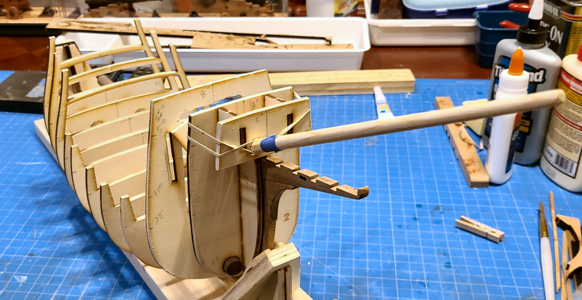
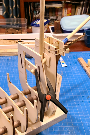
I was hoping to see some suggestions as to color, but I've made the decision to replace the walnut masts and spars included with the kit with light-colored hardwood dowels. I bought 8 dowels today from HobbyLobby in sizes from 1/8" to 7/16", sized every 1/16", getting 2 of two of them. I don't have to decide about color, but in the meantime, this gave me a light-colored bowsprit of an increased length, which will be sturdier, and sized so I had to take off only 0.020" in the diameter, more on the taper. And using my newfound bulkhead 16, I drilled 23/64" holes angled at 30 degrees for the bowsprit, and mocked up the assembly. While I was at it, and to be sure the bulkheads were aligned decently, I inserted most of the dowels which serve as bulkhead alignment devices. Nothing's glue yet, of course:
1677554734857.png
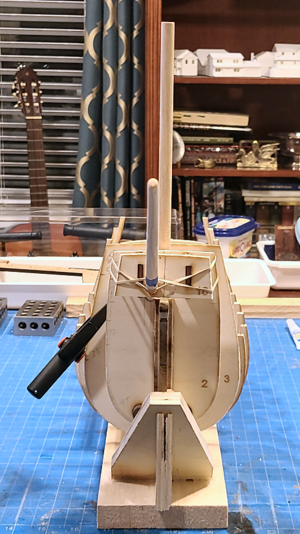
As discussed previously, the bowsprit is offset by about 10mm to the starboard, making room for it go pass the foremast without contact and be held by a bulkhead further aft.

As seen from the front, it does look a bit funny being offset, and maybe will more so when finished, but I will have right on my side. :cool:
1677554884573.png1677554898079.png
The patched piece behind bulkhead 3 will give me a good fit to the reduced size bowsprit than was already drilled in it, and the crosspiece in bulkhead 4 will be glued in place at final alignment of the frames and bowsprit. I imagine I will only be able to glue the bowsprit in place at the outer edge, if everything is covered with planking and such when installed, but even then it will be sturdier due to being held in 3 places.

Shaping the bowsprit went well, using my previously-used dowel-held-in-power-drill-while-sanding-against-belt-sander technique. It's quick, but a bit dangerous. We'll see if it continues to be a valid method, or if I have to resort to more manual methods.

Oh, I didn't mention earlier, but after getting the kit, I had the two large plan sheets copied by Staples into PDFs and had them make two copies of each as well. The copies are very close, but not quite exact, to the original plans, so I've been cutting up the plans with the kit to use as templates, etc. I also converted the PDF files to PNG bitmap files at good resolution (about 200 pixels per inch), and have determined factors to print at, so that I can print 8.5x11 sheets of detailed assembly areas that are very accurate in size. I did something similar with my Bonhomme Richard cross section model, and it served me well there, and I fell it will here as well. This gives me the chance to view full size plans in front of me, reduced sections at any time, and view/zoom in on any area of the plans on my computer. I've even determine the most accurate values I can for mast and spar diameters by zooming in on my computer screen, measuring pixels, and converting that to mm or inches. Works well for me.
 
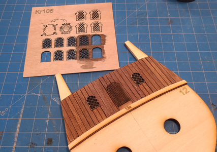
I've added siding, a door and a couple "windows" to the visible side of bulkhead 12. StellaMaris suggests painting it black, as is is within a 5" deep tunnel under the quarterdeck and detail will only rarely or partially be seen, but it didn't take long either:
1677611980553.png
I had no extra doors or windows from the kit, so made the door from scrap and the windows utilized the 0.5mm plywood grid intended to be used behind included window frames but now being supplanted by the brass etchings instead. I felt good about this as the excellent quality laser cut wood grids would not all go to waste. No hinges available for this one, so I'll just use strips of brass, as it again is not very visible.
 
I had to specifically ask my wife to not empty the trash can in my work room because you're not the only one...
Yeah, I've been putting plastic bags into mine, since then. Easier to remove and look for that part. Can't tell you how many times I emptied the contents of one bag into a new one, looking for a part, then found it had bounced or rolled somewhere else. My son, working under my desk on my computer a week ago, found an axle and truck/wheel from my HMS Victory cross section build of well over a year ago!
 
I've added siding, a door and a couple "windows" to the visible side of bulkhead 12. StellaMaris suggests painting it black, as is is within a 5" deep tunnel under the quarterdeck and detail will only rarely or partially be seen, but it didn't take long either:
View attachment 360201
I had no extra doors or windows from the kit, so made the door from scrap and the windows utilized the 0.5mm plywood grid intended to be used behind included window frames but now being supplanted by the brass etchings instead. I felt good about this as the excellent quality laser cut wood grids would not all go to waste. No hinges available for this one, so I'll just use strips of brass, as it again is not very visible.
I just realized when looking ahead at some other builds that the centered door in the above panel is right behind the mizzenmast. Like the door could not open outwards, and if opening inwards, a sailor (or captain) would have to squeeze past the mast to get through. Whoops! Well, the door will be even less visible than I described, if it's behind the mast. Still, makes me think I should at least add another door to the side. Or maybe just tell people "Don't Look In There!" :mad:
 
Back
Top