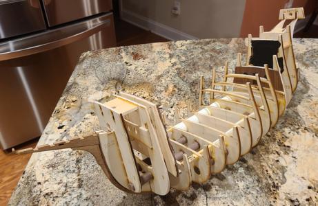
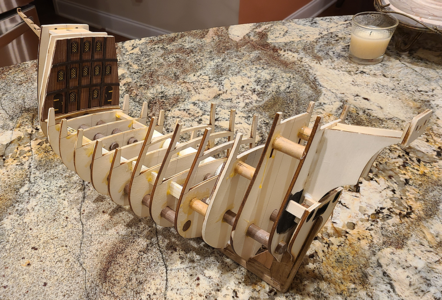
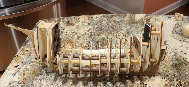
MarisStella Ragusian Carrack by Signet [COMPLETED BUILD]

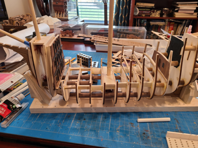
Continuing along with the bulkheads:
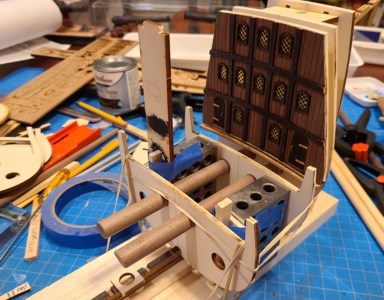
1678206647429.png
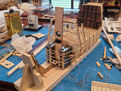
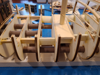
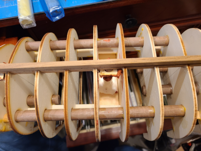
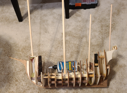
What I've been doing is to square and glue the foremost bulkhead, while inserting the alignment dowels and placing a bulkhead 2 or more positions behind it. The idea is to be sure consecutive bulkheads are properly in place to eventually allow free movement of the dowels into the assembly.

Here I've started using a little force to keep the aftmost bulkhead from raising. This is wrong, as I'll find out later.
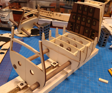
1678206774276.png

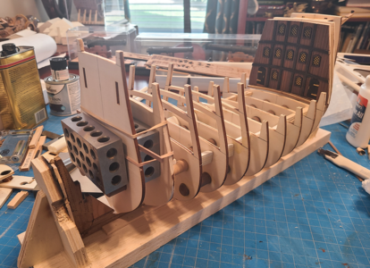
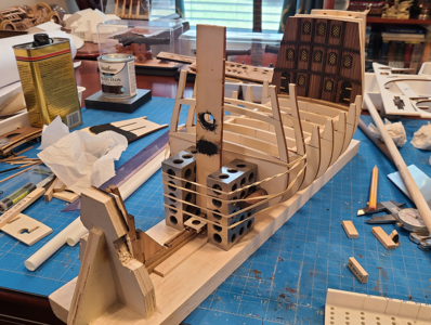
I got this far before I realized I really had a problem:
1678206916352.png
You will notice in the above picture that a band of racoons have decided to chew holes in the back brace of my "ship support". I was mad, at first, but it turned out that the holes line up fine with the rear dowels, allowing them to be inserted or removed while the frame is in the support, so I forgive them. :)

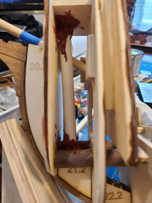
The problem: Without extreme care, it's easy for bulkheads after the first one to raise up very slightly. A little too much glue, not quite pushing the bulkhead down hard enough, maybe the fit isn't quite loose enough. This goes unnoticed, while you put in all the bulkheads using the foremost dowels and then several with the middle dowels. But in my case, this was raising up a little at a time without being noticed. Until I realized that there was no way the next couple bulkheads were going to slide over the dowels and still properly engage the keel. I went to bed that night resolved to bending the keel in order to make it all fit.

I woke up with a better idea: Tear all the bulkheads except for the ones that engaged the first dowel out, and do them again. Sure enough, I found glue in the bottom of most bulkheads notches where they meet the keel, indicating that I hadn't gotten them down far enough. It's easy to do: the dowels fit and everything looks good and is square, but it's rising up a little at a time.

Really, the best way to assemble this hull would be to assemble it all, all bulkheads, all dowels and keel, make sure it fits, then glue it in place. But that's difficult to do (your hands and those of at least one band of racoons are needed at the same time), and I was afraid that I'd be unable to properly glue the bulkheads to the keel without use of super glue rather than white glue, and didn't think I'd get the strength. The alternative is to build it a bulkhead at a time, but this requires extreme caution. Which maybe all other builders here already have, and it's just that I was lacking. I was also installing braces between the bulkheads to try to keep them square, and think this took my mind off of what was important.

I should mention that my problems and concerns in this area have nothing to do with the accuracy of the bulkhead and keel cuts: they are precise and excellent. In fact it is that precision that creates a problem if you're trying to assemble it improperly.

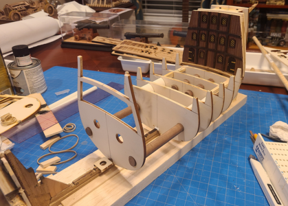
I used the traditional water method to remove all the bulkheads I could to get back to where my problem started, and made sure that the dowels maintained a nice slide fit through the holes, and yet the bulkheads were all completely down and in position on the keel. It's working much better:
1678207962556.png

In summary, it is most important with this kit that the frame bulkheads , dowels and keel fit completely in place, which can be tricky to do at one time or maintain a little at a time. We tend to concentrate on all the bulkheads being square and vertical, but in fact that matters much less than the frame alignment does.

Also, don't glue the finished bulkhead 17 in place like I did until later on. I glued it now because I thought Olha did in her video, but in fact she just fitted it in place, adding it later. With all the filling and sanding and such that will take place soon, the chances of getting that finished area damaged, or at least really covered in dust, is high, so don't copy me here. I tried to remove it, but too much glue, so intend to cover it for protection during some of the later operations.
 
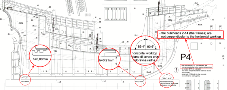
I should also mention a deviation I am making from the plans for this model, and to be honest, I'll bet others are doing so as well, possibly without realizing it. The side view construction of the hull shows the following, to which I have circled and enlarged some notes for clarity:
1678217493920.png

Two things are noted very specifically on these plans:
  1. The keel is NOT parallel to the work surface.
  2. The bulkheads are NOT perpendicular to the work surface (or the keel, as it turns out).
The first point shows the keel should point upwards toward the bow by 0.91mm in roughly 360mm, or by 0.145 degrees. Why? A standard reason might be to make the bulkheads vertical or perpendicular to the work surface, but that's not the case here. Another common reason is where the keel slopes a good bit when compared to the waterline, but I doubt researchers know the exact waterline on this ship within 1/7 of a degree. I see no reason for that.

Likewise, the bulkheads are not perpendicular to the keel by 0.6 degrees. More confusingly, since the keel is tilted upwards by 0.145 degrees, that means the bulkheads are not perpendicular to the keel by the difference of 0.455 degrees. Again, I really don't see a reason for this. Less than one-half of a degree change in angle of the bulkheads to the keel will result in a change in the top location by 2-5 thousandths of an inch. I've seen an incredible amount of precision work on these forums, but to tilt all bulkheads by 2-5 thousandths of an inch per the plan really seems excessive.

So - was there any question? My keel is laid parallel to my work surface. And my bulkheads are as close as I can make them to perpendicular to the work surface. I would imagine that the bulkheads actually tilt back, or forward, by more than that 5/1000", but not on purpose. I see no reason to assemble them otherwise, and doubt others have done so (although I'm sure someone will correct me).

I just wonder why this additional detail was included. Oh, it should also be noted that this information and angles were only added in the newer version of the kit, and were absent from those built by Olha and Jack Aubrey.
 
Last edited:
I wasn't complaining. Many times with forums you have no idea what your final post will look like, but this forum shows you all the time. What is different here, I think, is that the color scheme of the posting area is the same as the rest, while other forums it looks completely different, so is obvious it's not posted yet.
I agree here with you
 
OMG, I did it again! I thought this was all posted last night, and while the pics are still here, I lost almost all my text! I really gotta concentrate more!

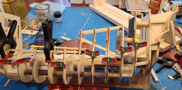
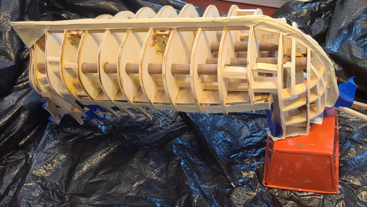
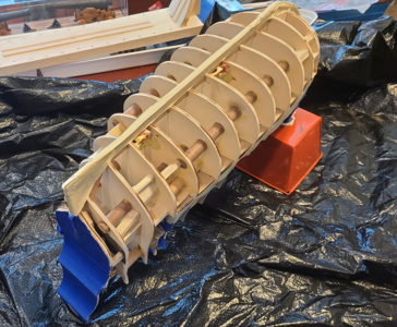
Continuing on locating and gluing the bulkheads in place, along with some additional bracing. As discussed above, going to great lengths to be sure that each bulkhead is seated completely into the notch in the keel and that the locating dowels slide easily through the assembly, until they are glued:
1678288981185.png
1678247245472.png

On the stern, I made a groove in the rear part of the keel, next to the rudder, for the planks to go into for a better fit. So, I'm placing scraps of planking in the groove to locate the final bulkhead #15:1678247282227.png

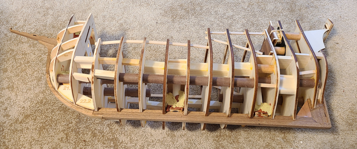
Finishing up the remaining bulkheads, and adding a few more stiffeners here and there, we have the basically complete frame:
1678247555269.png
1678247566572.png
1678247588037.png
1678247612743.png
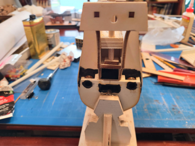
On the above view, you can see a hole in the spacer with "TOP" written on it for the Bonaventure mast and spar. I hope to add that to this model, to help add something different. The new plans show its size and location, but does not include materials for it. There is enough sail material to get the sail out of, if I can match stitching well enough.

Naturally, I'm thinking ahead to adding reinforcement between the bulkheads to help support the single layer of planking. While usually done with softwood, I had the crazy idea of using foam - not regular sheet foam, but low expanding foam like Quick Stuff. Please weigh in at this separate topic concerning this.
 
I've always been concerned with getting masts properly located and sturdy. The last couple models I built were cross section models, and even there, with the mast going through up to 5 decks, it was critical to to keep the mast exactly in the right position while doing all the decks, yet have the mast removable, until it was finally located in the proper position.

This model shows all masts located by only the mast locating blocks at the keel, and at the deck. Worse yet, most builders seem to not worry about their final location until they cut holes in the finished decking, and somehow everything lines up. That is NOT my experience! I know if I tried this, the masts would all be pointing to a different stellar constellation, and not be properly lined up. Plus I doubt they'd be sturdy enough. Experienced builders seem to be able to accomplish this, but I knew that wouldn't work for me.

I spent one night dreaming about support for masts, to be sure they were in the right place, and be sure when I inserted them, they'd go back into the right location (not missing the little hole and support at the keel), and be easy to fix permanently when the time came. My dreams mostly involved solid blocks of wood with holes drilled at the appropriate angles and all, and other than that, I hadn't worried about it.

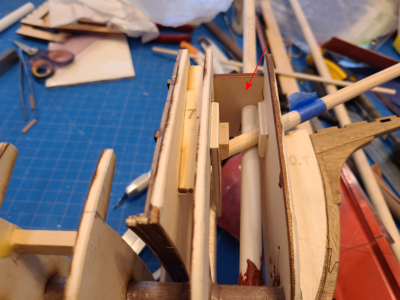
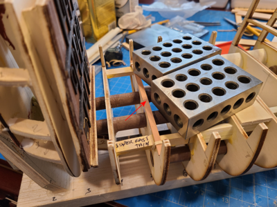
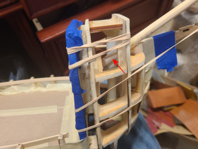
But then I was going through my scrap drawer, and ran across a bunch of thinwall plastic tubing I had, and - surprise! - they happened to be exactly the size to be a snug fit on the dowels I'd purchased for the masts. Starting with the Foremast, I decided to add another horizontal mast support at the top of the forecastle, place a piece of plastic tubing around the mast, held by the upper and lower supports, and somehow glue the tubing in place. Here's how the foremast is held:
1678505710172.png
The red arrow points to the upper, added support for the mast. Held in these two locations, that was really all I needed, but I was afraid that I'd miss the bottom support hole when installing. You know, when everything is all finished except that big glop of glue on the end of the mast to hold it in position? So I added a piece of plastic tubing which has a snug fit over the dowel between the 2 wood plates. The dowel is still held by the hole in the bottom plate and the top added plate, but the plastic tube acts as a guide and additional support. In the above picture, I added my favorite Bondo Glazing & Spot Putty to hold the tubing in position at the bottom (not yet the top). You can also see in the above picture where the off-center bowsprit passes by the foremast.

This is the same are with a glop of Bondo at both the top and bottom, to hold the plastic tube in place:
1678506008997.png
Yeah, I'm not so neat with this stuff, squeezing it onto a popcycle stick and the pushing it in place. But it will be covered.

Here I've added a similar plate to support the upper part of the mainmast, which will end up just below the main deck:
1678506120503.png
This is the only mast that is vertical on this particular ship.

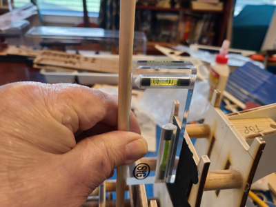
Next the mizzenmast. I'll go into a bit more detail on my methodology for this. First I held it in an exactly vertical position, after confirming the model was on a horizontal surface.
1678506263676.png

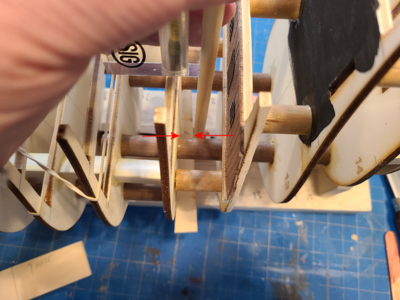
While holding it in this position, I used a tapered scrap of wood to record a measurement from the edge of the mast to a neighboring bulkhead. I place a pencil mark at the mast center, as low as possible, and then measure that distance with a dial caliper.
1678506414412.png
I repeat this process at the point where the mast will be supported just under the main deck, in case they're not the same (the bulkhead may not be perfectly vertical). If the mast is vertical, you use the second dimension to locate the hole for the mast, and you're done. On this model, all masts except the mainmast are canted forwards or aftwards approximately 2.2 degrees. I need to then account for this in the hole location to set it correctly. If the distance between the bottom support and the top is 3", which is about as it is here, then (engineering degree coming into use here - okay, basic high school trig will do it too) the hole has to be offset further back by 3" x Tangent(2.2 degrees) = 3" x 0.0384 = 0.115" (2.93mm). I measure this off on the piece to be located above, allowing a little extra for sanding fine tuning, and that locates the front-to-rear angle of the mizzenmast. The first mast should be located exactly vertical to your work surface, and then I align all other masts to be parallel to it side-to-side by sight. This is easily done as the glue is drying. Fore-to-aft angle can be fine-tuned a bit as well, depending on your hole clearances.

This photo shows the foremast and mainmast in place and aligned:
1678506947803.png
The piece of plastic tubing I used is in the foreground. This was added during final alignment, as in some cases the tubing goes through the top hole as well.

As mentioned previously, I think I'd like to add a Bonaventure mast and yard to this model. I previously drilled a piece of plywood at the proper angle for it to mount on the poop deck, but didn't quite glue it at the right angle. So I enlarged the hole very slightly, added another wood plate below it, and a movable piece atop that drilled to accept the Bonaventure mast. I could then insert the mast and move the plate with the hole around until I had the proper angle to the rear, and vertical side-to-side. No tubing was used for this mast (or the bowsprit, for that matter).
1678508557871.png
This isn't (quite) as crooked as it looks in the above pic. Camera slightly off-center and perspective makes it look worse that in is. I think it looks okay in person.

While doing all this, I found that the putty worked well to keep things in place, but did not adhere well to the plastic at all, allowing it to rotate. I needed a better way for permanent attachment. At the top of the positions, I puddled a lot of Titebond Quick & Thick glue and allowed it to dry.
1678507573483.png

I bought some heavy duty caulk/adhesive to do the bottom, because puddling glue there just runs everywhere and makes a mess, and while it sticks fine to plastic and wood, instructions that I missed mentioned it took 3 weeks to cure completely - no good for this purpose.

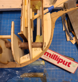
After some research, I thought that Green Stuff putty would be good to use, but no one had it locally, so I got some Milliput Standard Epoxy Putty from Hobby Lobby to use instead. It has the usual 2 component epoxy system, where you need the two components into a ball for 5-6 minutes, then shape and place where you want. It dries solid within 90 minutes, is paintable, and sticks to almost everything (moist fingers helps keep it from sticking on them). Here's the foremast after placing this putty at the top and bottom to properly secure the plastic tubing to the top and bottom plates, as well as the bulkheads:
1678507623805.png
Milliput putty dries rock hard and I feel confident it will serve well in this position.

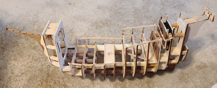
All 4 masts are now in place, secured very well to the hull, yet all are easily removable. Holes to locate them are just under where planking will be placed, so it will be simple to plank around the masts, and still remove them for other operations. Bowsprit was removed for this picture:
1678507740234.png
I'm hoping to hear more from Bryian who in my other thread on Great Stuff Expanding Foam said he had some successful experience using it, but I hope to use it on at least some elements of the hull structure, both to stiffen it and, hopefully, to provide a backing for the single layer planking, but that will wait for another day. In the meantime, I'm happy with my mast locations and security, and confident I can remove and replace them during construction as needed until one day they are permanently secured to the model.
 
Last edited:
Hello Signet, Super great protocol and great progress. At the end of one of your posts, you expressed wishes, among other things, that you would soon be 80 years old. I also have one wish, and I want to be able to do it perfectly at your age. Great work and great respect.
 
I've been temporarily laying some wood planks in place on the main deck, and felt the curve toward the bow was a bit too extreme (down, then up), so added some thin strips of wood to make the curve more even:
1678764255351.png
I've added some additional bracing between the bulkheads, for strength, so this is how it appears now:
1678764303939.png
1678764318297.png

After getting some comments in my Crazy Idea - Great Stuff Expanding Foam thread, especially from Olha, I am getting very nervous about using foam to fill between the bulkheads. Not so much about having a problem with the foam, which I still think (in my inexperienced mind) I could form quite well, but in the lack of support and nailing locations to apply the hull planking. I've never made a planked hull model, and this is single-planked, so I'm really concerned. I had hoped that if I bend each plank properly (got an electric bender), and spent enough time on each plank, it would not be a problem, but that might well be too simplistic.

Add that to the problem that I've added additional small bracing between bulkheads which would work well with foam, but prevent real wood blocking, and I'm having nightmares. I can really see this thing going in the trash within the next month, and think I may have really bitten off more than I can chew.

And now to bed, to think and dream even more about it.
 
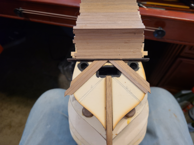
Working on the stern next (anything to avoid working on hull planking, or worse, preparation for hull planking). Rather than walnut, I had some slightly oversize softer, lighter wood from another project I used for the first layer:
1678936203264.png

The Supervisor noticed this deviation from plans with some concern:
1678936255099.png
but smartly decided to ignore it and take another nap.

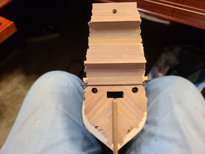
Upper, curved portions of stern have been added, and work has begun on the diagonal planking on the lower portion of the stern:
1678936339598.png
You will notice a horizontal piece separating the upper from the lower portion of the stern. Probably due to an error in locating the rabbiting of a groove for this diagonal planking, the last bulkhead sticks out a bit further, after planking has been added, than the curved portion above it. I always kinda thought that there needed to be a separation of diagonal versus horizontal planking, so took this opportunity to add this horizontal piece, a small "shelf" basically, that planking from both above and below terminate to. It will be left sticking out a little all around, as a bit of "trim" or moulding and I think will enhance the look when done. I have stained this piece (it will be touched up later) with dark walnut, as I did the window frames and expect to stain other hull details, such as wales and such.

This is clumsy for me to hold, half the time being held between my legs at my desk/workbench. Unfortunately, my desk is mostly occupied with tools, scraps and other junk, leaving little room for the model, unless it is in the cradle I made for it.

Unlike the window frames, which I inset in the paneling like Olha did, I decided on the stern to add the ring mouldings around the cannon ports and rectangular moulding around the tiller on top of the planks. They aren't very thick, and in this case I prefer them that way. Plus, I don't have to worry about fitting the planks closely around them.
1678936893441.png

Before trimming the planks, I used a piece of tape to mark the center of the stern, then added other pieces to mark the edges to be trimmed. This isn't quite a straight line (from any angle, really) and the curves make make marking a straight line rather difficult, so I sighted along the hull, measured the drawings, etc. and hopefully got a happy average as to the location of the edge. It can later be adjusted slightly to get the best planking hull lines.
1678937159849.png

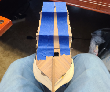
Basic profile of stern is complete, except for any mods required as mentioned above, and fairing it in with other bulkheads for planking:
1678937224592.png
A good bit of sanding to do. Something I've noticed (now that it is complete) is that while Olha does not show any paper or other separation on her planking, even planks on the side of the hull which have been sanded quite a bit show such plank separations. Mine won't have them. Too bad for me, but I expect planking to be hard enough without providing caulk lines or other separation lines as well. I beveled the cabin area planks a bit, to separate them, and may do that on the deck, but not here.
I also spread out all my 1.5x4mm walnut planks (about 200 of them) to try to be able to pick those that match better in color. Olha did this as dark and light, but I have found also every shade in between, as well as planks that start out dark and end up light, and others with an orangish tinge. I talked my wife into giving my array of strips a look and do some sorting, what with her recent cataract surgery in both eyes, but couldn't keep her interested for more than a half hour. My goal is to just grab a pack of color-sorted strips of a light or dark or medium color, to restrict color changes in any given area. I doubt this will work that well, but will hopefully help some.
 
Working on the stern next (anything to avoid working on hull planking, or worse, preparation for hull planking). Rather than walnut, I had some slightly oversize softer, lighter wood from another project I used for the first layer:
View attachment 363171

The Supervisor noticed this deviation from plans with some concern:
View attachment 363172
but smartly decided to ignore it and take another nap.

Upper, curved portions of stern have been added, and work has begun on the diagonal planking on the lower portion of the stern:
View attachment 363173
You will notice a horizontal piece separating the upper from the lower portion of the stern. Probably due to an error in locating the rabbiting of a groove for this diagonal planking, the last bulkhead sticks out a bit further, after planking has been added, than the curved portion above it. I always kinda thought that there needed to be a separation of diagonal versus horizontal planking, so took this opportunity to add this horizontal piece, a small "shelf" basically, that planking from both above and below terminate to. It will be left sticking out a little all around, as a bit of "trim" or moulding and I think will enhance the look when done. I have stained this piece (it will be touched up later) with dark walnut, as I did the window frames and expect to stain other hull details, such as wales and such.

This is clumsy for me to hold, half the time being held between my legs at my desk/workbench. Unfortunately, my desk is mostly occupied with tools, scraps and other junk, leaving little room for the model, unless it is in the cradle I made for it.

Unlike the window frames, which I inset in the paneling like Olha did, I decided on the stern to add the ring mouldings around the cannon ports and rectangular moulding around the tiller on top of the planks. They aren't very thick, and in this case I prefer them that way. Plus, I don't have to worry about fitting the planks closely around them.
View attachment 363174

Before trimming the planks, I used a piece of tape to mark the center of the stern, then added other pieces to mark the edges to be trimmed. This isn't quite a straight line (from any angle, really) and the curves make make marking a straight line rather difficult, so I sighted along the hull, measured the drawings, etc. and hopefully got a happy average as to the location of the edge. It can later be adjusted slightly to get the best planking hull lines.
View attachment 363175

Basic profile of stern is complete, except for any mods required as mentioned above, and fairing it in with other bulkheads for planking:
View attachment 363176
A good bit of sanding to do. Something I've noticed (now that it is complete) is that while Olha does not show any paper or other separation on her planking, even planks on the side of the hull which have been sanded quite a bit show such plank separations. Mine won't have them. Too bad for me, but I expect planking to be hard enough without providing caulk lines or other separation lines as well. I beveled the cabin area planks a bit, to separate them, and may do that on the deck, but not here.
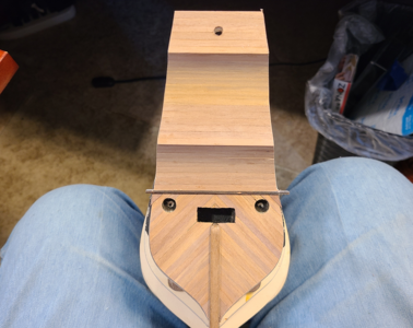
I also spread out all my 1.5x4mm walnut planks (about 200 of them) to try to be able to pick those that match better in color. Olha did this as dark and light, but I have found also every shade in between, as well as planks that start out dark and end up light, and others with an orangish tinge. I talked my wife into giving my array of strips a look and do some sorting, what with her recent cataract surgery in both eyes, but couldn't keep her interested for more than a half hour. My goal is to just grab a pack of color-sorted strips of a light or dark or medium color, to restrict color changes in any given area. I doubt this will work that well, but will hopefully help some.
Good morning. Excellent posts- explanatory. Your process and attention to detail is admired. I can learn from this for sure. Cheers Grant
 
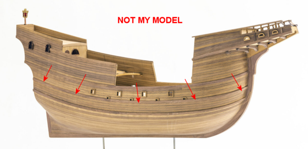
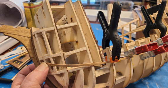
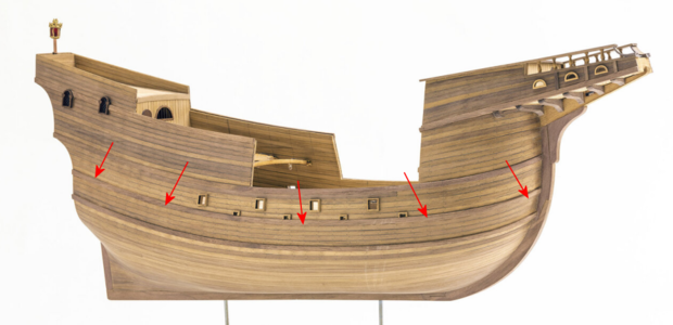
However I prepare the hull, I need to bend most of the strakes and planks quite a bit vertically along the side (against the natural bend of the wood), and felt I might have better luck making a jig of some sort to do this. The photo below is from Olha Batchvarov's build of this model, which I'm sure mine will NOT look like, but which I have marked with arrows to indicate the first strake I shall attempt to make and apply, with all others being continued from it:
1679020967156.png

To start with, I took a piece of 2x2mm wood I had to clamp temporarily in place to determine where the top of the rubbing strake at main deck level (indicated above) will cross the bulkheads. My goal here is to keep the top of this strake at the top of the waterway at the edge of the deck, so that drain holes can be cut in the bottom of the first plank above it, maintain the end points at the right location, and have as smooth a curve as I can:
1679018303393.png
After positioning the 2x2 strip, I marked each bulkhead at the top of the strip, locating the top of the main deck strake. I did the same separately at the bow end, with its extreme curve:
1679018396449.png

I used strips of tape positioned along my lines to measure distance along the strake. in retrospect, I should have used the horizontal distance instead of the strake position, as this made my length wrong. It remains to be seen if this needs to be redone.
1679018497671.png
While the tape was taunt, I marked bulkhead and rib locations for distance measurement. I then measured at each point/distance, the height above my work surface to the intersection of the top of the strake with the bulkhead.

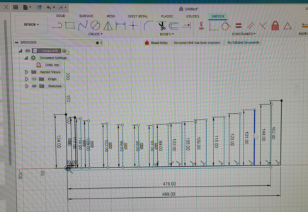
I used Fusion 360 to accurately draw this profile, basically using X-Y coordinates (which don't exist in Fusion 360, so had to dimension each height separate):
1679018616971.png
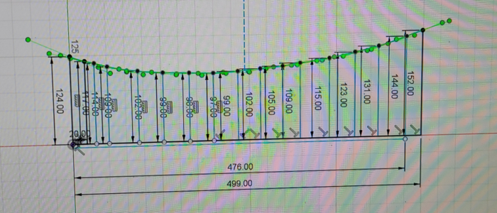
Using the points located above, I drew a spline to smoothly connect all the points:
1679018663838.png

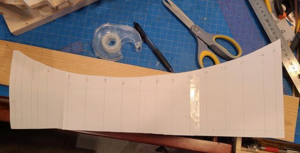
Realizing that wood, when bent, tries to go back to its original shape, I increased the bend by a 50% fudge factor, printed out a template on 3 pieces of heavy paper taped together, and chose a piece of wood for the jig:
1679018752875.png

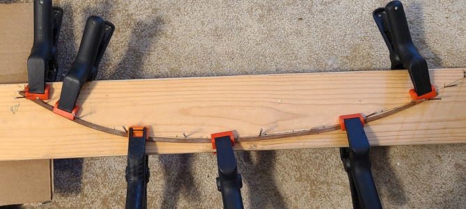
The wood strips were soaked in hot water for about 20 minutes. Small nails were placed on the inside of the curve, and a couple on the outside to hold the ends, and the 2 strips located and clamped in place:
1679018920311.png

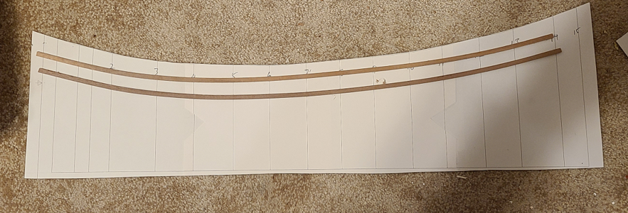
After the strips were dry (maybe 4 hours), I removed them and compared them to my original template (without the 50% added curvature) and was pleased with the result:
1679018966008.png

I've placed the two strips back in the jig until I intend to use them. I have to bend the bow horizontal curvature before use, hoping that doing so by soaking and heating with an electric plank bender won't remove the vertical curve which seems good. I already tried the Hobby Tools plank bender I bought to try bending that way, and it didn't bend the planks at all!

1679017936057.png
 
The strake is going to look perfect. Nice strategy you used to achieve the exact angle! Magic Mike
I realize when looking at other builds of this model that only Olha ran all the planking parallel to the strakes. Other builds I've seen run the planking in a way that does not bend it upwards, just running the way the plank wants to bend most easily, which would be far easier to do. But Olha has done it according to the drawings and instructions (which read "This way of planking is important, because the planking strips are set up like the real boat and its main characteristic is that the lines of the planking strips do not overlap with the rubbing strake lines or wale lines"). It would be far easier to not do it this way, as others have done, but I will at least attempt to do it correctly.
 
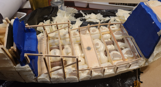
I've decided to try the using Great Stuff expanding foam to fill in between the bulkheads. The main purpose is to strengthen the structure and provide a backing for additional glue to adhere when gluing planks in place. The secondary purpose is that it seems like a neat idea, and wanted to try it. This is against most advice I have been given, including my wife's who said if this destroyed my kit, I wasn't getting another one.

My intention is to glue the planks to the bulkheads and/or foam, using white glue if possible, CA glue on bulkheads only if necessary, or maybe even a combination of the two (CA on bulkheads, white glue on foam). After applying the foam between bulkheads, I will use a hot wire foam cutter, primarily, to remove the majority of foam extending from the bulkheads, and sand to a final contour. As with similar filling using balsa or other wood, it doesn't need to fill every gap, just provide as much support as reasonably possible.

Going in, I wasn't sure how much foam I would actually use; if it starts running everywhere and messing stuff up, I'll stop. I'll start small, especially in highly curved areas needing support more, and just see what happens.
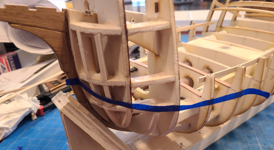
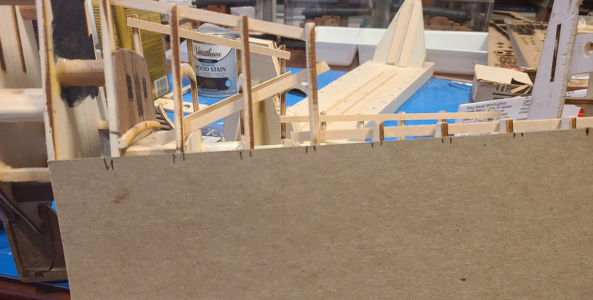
I started by trying to protect any finished areas, or large areas into which I would prefer the foam not go. I /think/ I can remove the foam from anywhere, but it will be neater and take less time if it is mostly where I want it to be. So I need to protect everything, even though I may not get that far. I started with the area above the main deck. I first took a piece of cardboard and located along its length the location of the bulkheads:
1679249784774.png
Then I measured the inside width between inside of bulkheads, divided by 2, and marked that distance out from the edge of the cardboard. Then measured the extreme width, and did the same, and finally cut the piece to that outline.

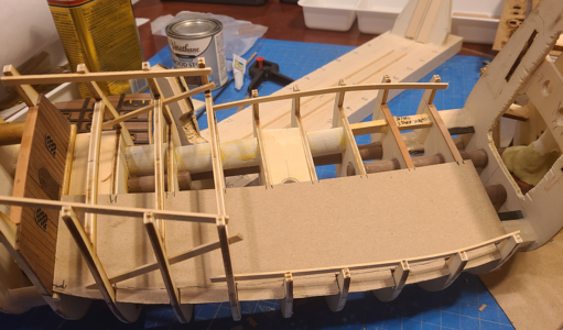
The measured and cut cardboard fit like this:
1679249902452.png
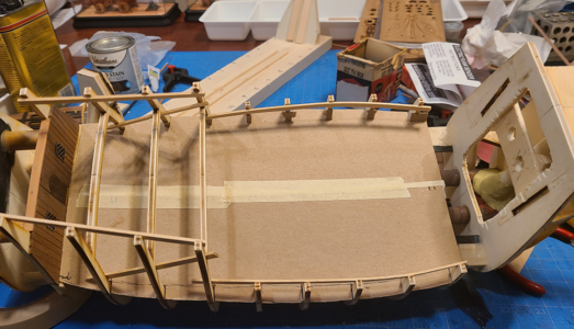
I traced this outline for the other side, but rather than cutting out for the bulkheads, I just bent the tabs up, and put both into place:
1679249970084.png

I protected and glued into place the finished bulkhead 17, with doors, windows and planking, into place. I really don't want foam on any finished areas:
1679250115942.png

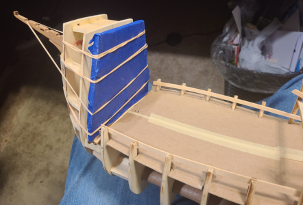
You may recall I inserted pieces of plastic tubing for the 3 major masts to fit into, but the bowsprit simply goes through 2 holes in 2 of the bulkheads. When foaming this critical bow area, the internal portion of the bowsprit is exposed to any foam or filler:
1679250289186.png
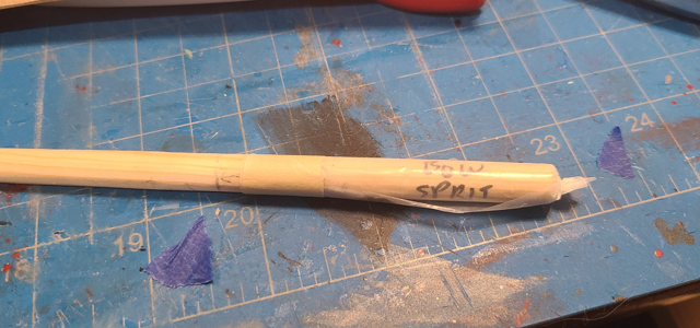
And yet, the bowsprit had to be in place when doing the foaming to allow it to be positioned correctly later (okay, I could have drilled through the foam, but didn't think of that then). To keep the foam from contacting the bowsprit and "gluing" it in place, I wrapped the end of the bowsprit in waxed paper and taped it in place:
1679250719956.png
Even though the waxed paper is loose, by rotating clockwise during insertion, it stays in place fine.

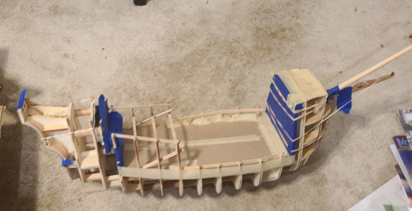
This fuzzy picture shows the various protections in place, to keep foam away from things I don't want it to touch, or just limit its migration:
1679250831330.png
The stern has been covered with tape as well. I used painters tape on areas which had been finished, and masking tape on areas that were not.

My intention was to do the foaming in the garage, where if it (or I) went wild, it would cause less damage (provided I kept it away from my wife's car, in which case I'd be moving out anyhow). But high temperatures today and in the near future are in the 50s F, and Great Stuff prefers closer to 75F. So I used a large trash bag to protect my desk, put on old clothes, and set up ready to foam away:
1679251024026.png
1679251046483.png

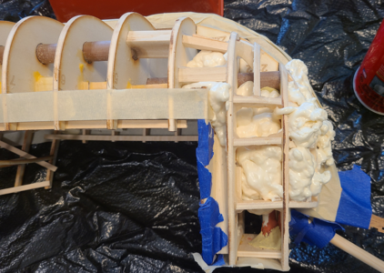
I began by foaming the bow area, around the bowsprit, which is most curved, knowing it needed the most support. My thought is to foam a little at a time, slowly, and stop if I ran into trouble (or preferably before it):
1679251148422.png
One thing that surprised me is that the foam did not expand as much as I thought it would. I tried to keep the foam more or less level with the bulkheads.

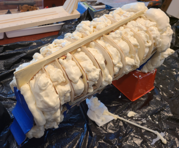
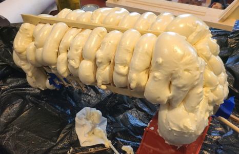
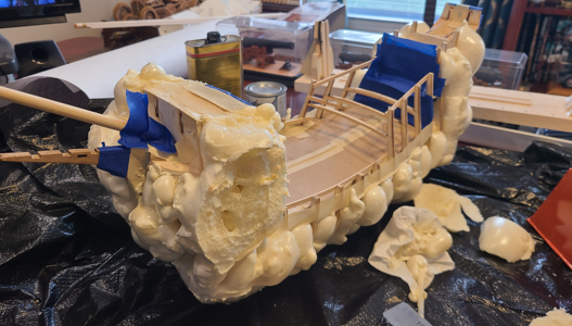
I didn't take any more photos until I was finished; I ran out of foam, actually, not quite filling areas along amidships as I had intended, but I noticed that the foam had continued to expand, especially at the bow:
1679251711131.png
1679251729953.png

An hour or two later, as I write this, I notice the foam is still expanding:
1679251775743.png
Looks like most areas will be filled when it's done.

I had intended to not post any of this until at least tomorrow, after which I would see the final effects of the foam to my model, and also show the removal of it, hopefully ending up with an excellent-looking result.

But - if I have to wait, so do you. I'm only posting the result to this point. I will discover the result tomorrow, and possibly/probably begin removal of excess foam then. So we will both find out, after tomorrow, whether I am continuing this build of a Ragusian Carrack, or if I have changed my goal to a 1/3 scale model of the Michelin Man. Fingers crossed, everyone, okay? :oops:
 
I played a bit with the hot wire foam cutter last night, trying to get a start on removing the foam, but it bogged down toward the center of thicker areas, as did a saw.
1679365199288.png
The foam had not hardened sufficiently in those areas, and just gummed things up, so I set it aside until today.

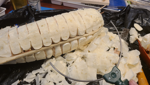
It turns out that Great Stuff expanding foam, while it is certainly a foam, is a bit more "rubbery" than the white sheets of foam many of us have used for hobbies, etc. That makes it a bit tougher to cut, as it is resilient. And the hot wire cutter goes through it much more slowly than any other foam I had tried it with. So, most of the larger and thicker pieces were cut with Japanese Flush Cut Saw. Despite it's name as a Pull saw, as long as it had support, it cut through this foam both ways. After most of the big stuff was cut off, I could use the foam cutter more easily:
1679365529498.png
Naturally, the foam goes into places you don't want it to, and stays out of some that you would rather it fill up. Working with the (cheap) wire cutter was slow with this foam, best taking shallow cuts, and moving the cutter back and forth like I was sawing it. I also had to watch out because the bulkheads on this model are some kind of ply"wood"; the outer ply is fairly hard, but the single inner ply is very soft. I wouldn't be surprised if it was balsa, or even foam, so can easily be damaged.

Continuing on trimming excess foam, there is a lot of scrap, of course, and mess:
1679365735452.png
When done, I measured about 4 ounces of scraps, so using the 12 ounce material weight on the can, I've added about 8 ounces weight in foam to the model.

In removing the cardboard over the main deck area, I found that foam had adhered in some areas (expected). While it was above deck level a in some areas, it wasn't much, but then I wasn't trying to support the main deck, I was just trying to keep too much extra foam from areas that would be harder to clean:
1679365917759.png

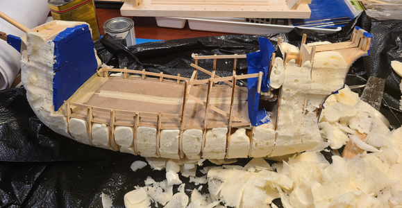
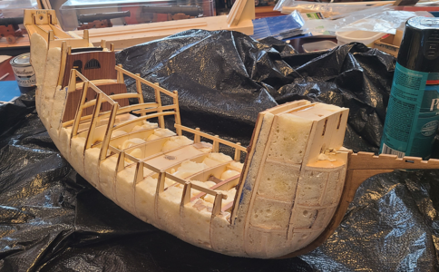
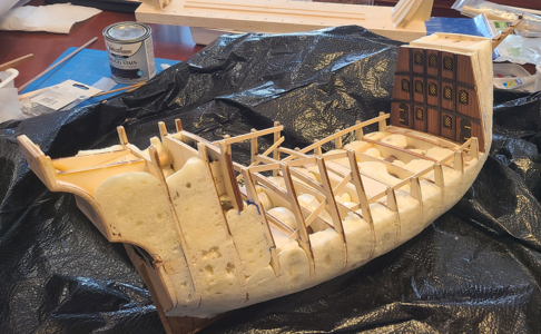
After removal of the protecting tape, and doing 95% of the extra
foam removal and smoothing, I had reduced my Michelin Man Blob to something looking more like a ship hull again:
1679365993333.png
1679366026194.png

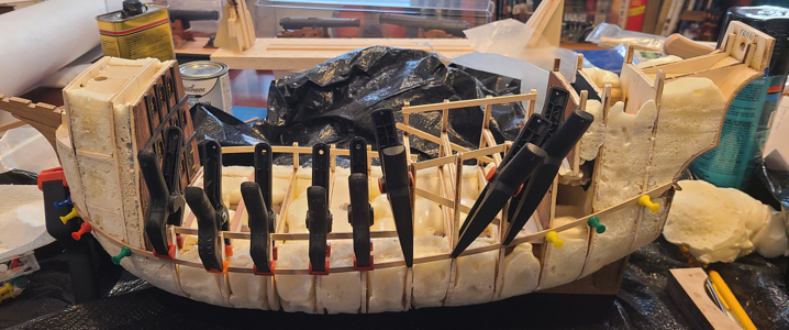
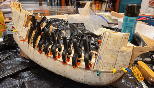
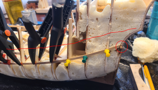
Planking started with the plank below the rubbing strake at level of the main deck, curving upwards at each end in the trademark Carrack/Galleon manner. For this plank, and the one on the opposite side, I used white glue to adhere to both bulkheads and foam, and went back over with some thin CA where I felt extra adhesion was required. I was able to clamp this plank fairly well, but that won't last forever:
1679366240283.png
1679366260354.png

A bit of a concern is that while all hull planks are supposed to be one piece from end to end, there will be many that are too long for the 500mm strips included with the kit. This view shows one side a bit short, and there will be 5 on each side going up from there that need to get longer by almost an inch:
1679366537560.png
For those 5 or so planks on each side, I will have to make them in 2 pieces, and have a splice somewhere. I haven't decided where: For strength, I'd like to have them join right over a bulkhead, but the joint will show (and while there would be joints in ship planking, it wouldn't only be in this location). The alternative is to plan for the joint to be under one of the many external braces on the model. I'll just have to see.

Okay, while the foam helps in some ways, and limits in others, the foam itself is done with, and I'll make some general observations concerning its use here:
  • Don't expect expanding foam to act like preformed foam. It is somewhere rubbery, harder to cut, harder to sand.
  • Use of substantial amount of expanding foam makes the hull framework really rigid. It locks in the braces I had already used, and feels like one solid piece. And in this case added about a half pound to the hull weight, which I consider a plus.
  • For the vast majority of the foam, it expanded outwards, not too much inwards. It didn't even bulge the cardboard very much. Where it expanded from inside between two parallel bulkheads, it expanded very nearly straight outward, not expanding width-wise, as that portion's width had already been determined by the bulkheads.
  • Obviously, it's easy to use too much foam; I got WAAAY more expansion than I wanted where I used more foam. And I ran out of foam before finishing every area I had intended, but I think it's okay as-is and doubt I'll add any more.
  • There was NO distortion of any bulkhead or panel, indicating that the foam did not provide enough force to do this, and that it primarily expanded outwards.
  • There was NO indication of glued braces or joints in the frame being loosened by the foam, like bulkheads pushed away from each other.
  • There was NO apparent distortion of the structure; everything appears to still be square (or as square as it was).
  • In short, the foam caused none of the structural problems that I and others had anticipated. Of course, it wasn't confined in place with outside planking; if it were, I'm sure it would be a different story.
  • It probably did save me time over doing it the "right" way, with wood blocking between bulkheads. While trimming and sanding were more of a problem, creation and placement of the wood blocking would have, I feel, taken a good bit more time. Of course, wood blocking would definitely be superior, I don't doubt that for a moment, and could hold nails and pins at any location.
Would I make another model using the foam? Possibly not. I think I'd try very hard to get my wife to let me buy a good scroll saw that can let me cut blocks that would be well-shaped upon insertion, and require less shaping and sanding afterwards. But if she said no? I really don't know. In the end, I didn't expect a huge gain by using foam; I wanted to try it as an experiment as much as anything else. And at least I accomplished that.

I hope this will be useful to anyone thinking about using this procedure in the future.
 
Back
Top