-

Win a Free Custom Engraved Brass Coin!!!
As a way to introduce our brass coins to the community, we will raffle off a free coin during the month of August. Follow link ABOVE for instructions for entering.
-

PRE-ORDER SHIPS IN SCALE TODAY!
The beloved Ships in Scale Magazine is back and charting a new course for 2026!
Discover new skills, new techniques, and new inspirations in every issue.
NOTE THAT OUR FIRST ISSUE WILL BE JAN/FEB 2026
You are using an out of date browser. It may not display this or other websites correctly.
You should upgrade or use an alternative browser.
You should upgrade or use an alternative browser.
Misticque, 1/36 - Build Log by Moreplovac
- Thread starter moreplovac
- Start date
- Watchers 18
A bit more frame assembly…
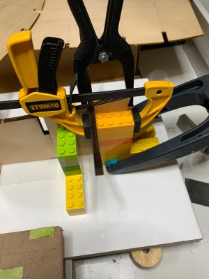
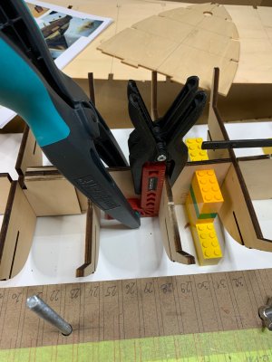
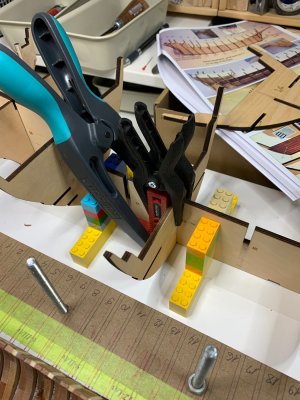
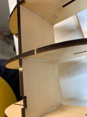
For every frame i add some extra glue on edges, not sure if needed i just have that habit..
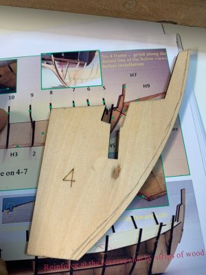
For frame #4 assembly instruction calls for tapering on “dotted” line but dotted line is not marked on the frame, just on picture, so i sanded a bit and will finish up with more sanding if needed.
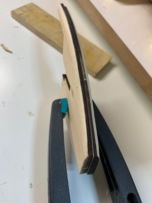
Frames 4 tapered with scalpel, file and sanding paper. It is easily cut wood as long as you follow the grain.
Then i remove some parts from frame, like cannon carriage
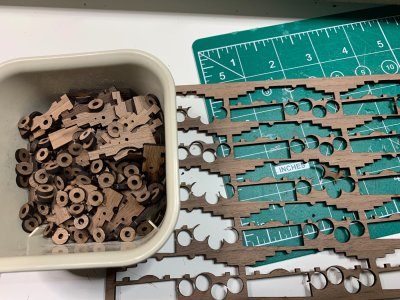
.. and some other parts. They are very fragile, 2mm thick wood breaks very easily.
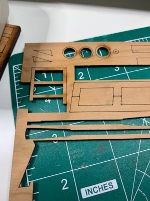
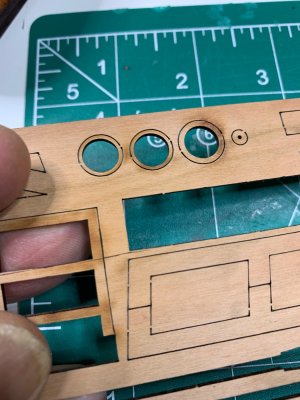
This is cabine door, not a big deal since they will be replaced anyway with scratch build one; door from the kit look a bit more from 20th century..
Also had some time to remove laser burns from the keel (made from few parts) that will be glued to the ship.
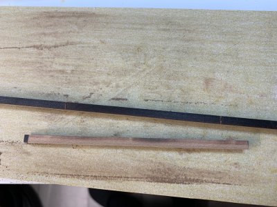
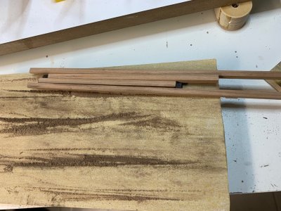
Looks like i cannot get rid of sanding ; maybe should start with plastic kits..
Happy modelling.


For every frame i add some extra glue on edges, not sure if needed i just have that habit..

For frame #4 assembly instruction calls for tapering on “dotted” line but dotted line is not marked on the frame, just on picture, so i sanded a bit and will finish up with more sanding if needed.

Frames 4 tapered with scalpel, file and sanding paper. It is easily cut wood as long as you follow the grain.

Then i remove some parts from frame, like cannon carriage

.. and some other parts. They are very fragile, 2mm thick wood breaks very easily.

This is cabine door, not a big deal since they will be replaced anyway with scratch build one; door from the kit look a bit more from 20th century..

Also had some time to remove laser burns from the keel (made from few parts) that will be glued to the ship.


Looks like i cannot get rid of sanding
Happy modelling.
I love this….I thought I made a mistake once ... but I was wrong.

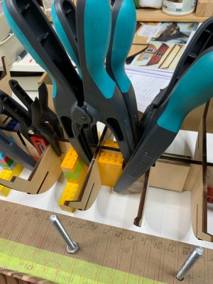
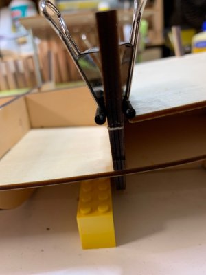
Good afternoon. An example of Lego “squaring “….A bit more frame assembly…
View attachment 505058
View attachment 505057
View attachment 505056
View attachment 505055
For every frame i add some extra glue on edges, not sure if needed i just have that habit..
View attachment 505051
For frame #4 assembly instruction calls for tapering on “dotted” line but dotted line is not marked on the frame, just on picture, so i sanded a bit and will finish up with more sanding if needed.
View attachment 505050
Frames 4 tapered with scalpel, file and sanding paper. It is easily cut wood as long as you follow the grain.
View attachment 505049
Then i remove some parts from frame, like cannon carriage
View attachment 505054
.. and some other parts. They are very fragile, 2mm thick wood breaks very easily.
View attachment 505053
This is cabine door, not a big deal since they will be replaced anyway with scratch build one; door from the kit look a bit more from 20th century..
View attachment 505052
Also had some time to remove laser burns from the keel (made from few parts) that will be glued to the ship.
View attachment 505048
View attachment 505047
Looks like i cannot get rid of sanding; maybe should start with plastic kits..
Happy modelling.
Thanks Grant, it is a perfect square when more than 4 are needed.. have a box full of bricks... just in caseGood afternoon. An example of Lego “squaring “….. I am also a Lego user in my builds. So helpful. Cheers Grant
Cheers
Frames 4 and 5 were attached; frame 5 has very tight spot so I did not put any glue on it, just slide it down and later apply small line of glue at the edges.
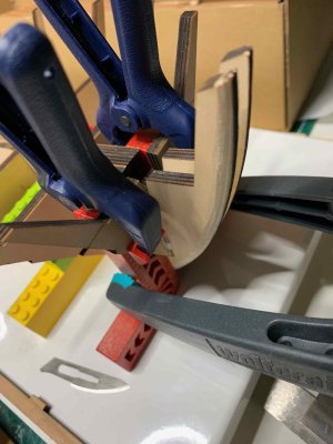
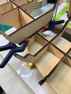
Installing reinforcing plates 35..
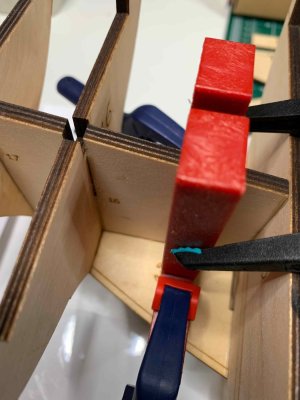
Then I wanted to install keel, consisting of few pieces which I sanded (laser burn removal) yesterday. Unfortunately, once you put in frame 18, you cannot attach part of the keel at the stern...
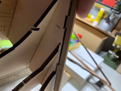
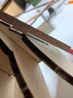
So, options are to remove frame 18 or to slightly modify keel so it will fit.. I cut a small part of a join (not sure what is correct name for this join) and tested fitting OK.
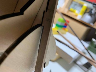
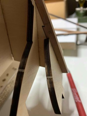
Just keep your mind on this step as it is not mentioned anywhere in manual; anyhow not a big deal..
I am not sure what else might challenge keel installation so I leave it out for now, until I get a better grasp on about of tampering needed. And don't want to damage keel while working on model.
..

Installing reinforcing plates 35..

Then I wanted to install keel, consisting of few pieces which I sanded (laser burn removal) yesterday. Unfortunately, once you put in frame 18, you cannot attach part of the keel at the stern...


So, options are to remove frame 18 or to slightly modify keel so it will fit.. I cut a small part of a join (not sure what is correct name for this join) and tested fitting OK.


Just keep your mind on this step as it is not mentioned anywhere in manual; anyhow not a big deal..
I am not sure what else might challenge keel installation so I leave it out for now, until I get a better grasp on about of tampering needed. And don't want to damage keel while working on model.
..
Last edited:
Second layer of reinforcement is #35, on both ends of the model and both can be installed only in one direction..
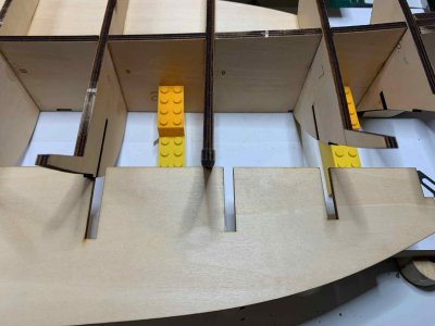
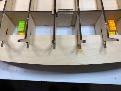
I also had to remove few lego bricks leaving it only 3 bricks high because reinforcement will be kicking it..
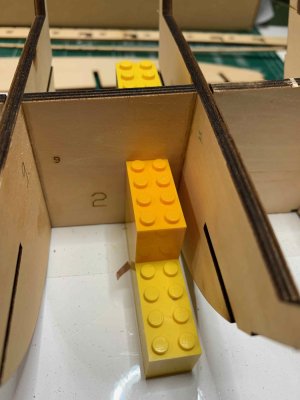
All frame groves where reinforcement will be added needs to be filed lightly to remove burn and to allow easy slip. Still some push is needed and also, upper part of a frame (where the groves is) can be very gently spread upwards to allow easier slide...
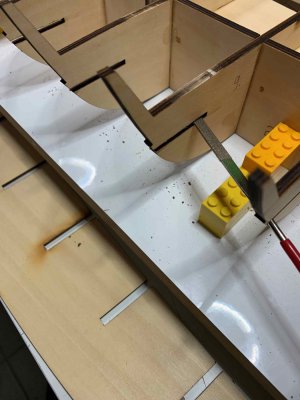
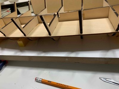
And another gotcha - between frames 10 and 11 where that small piece of plywood is glued to protect keel assembly line, the reinforcement pieces (#34) have to be adjusted. Noted that a bit too late and checked manual but no mentioning about that.
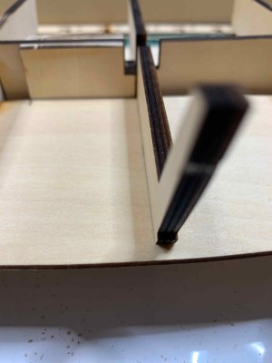
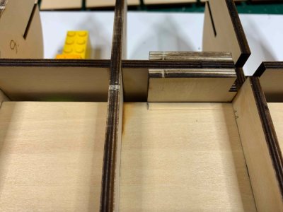
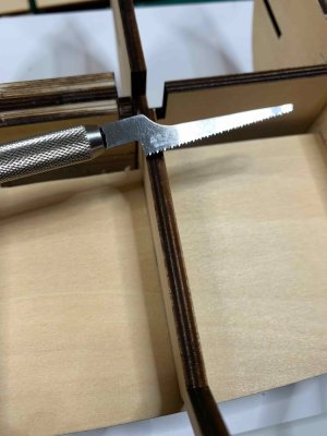
Since plate #34 is 3mm tick, it is easier to slide it all the way to the keel, mark lines for a grove that has to be open and use scalpel or small saw to cut opening.
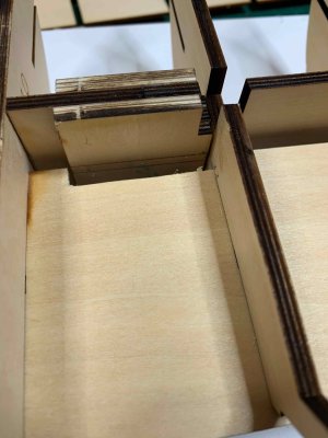
Now reinforcement is all the way in and fit nicely to frames..
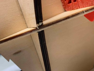
Checking it out..
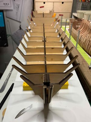
I just put another line of glue on #34 and frames to secure it even further, but it is not needed, the fit is very tight.
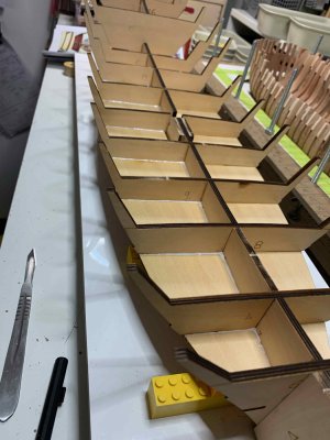
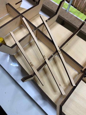
Next, will be adding deck surface and in the meantime prepared reinforcement for frames 13, 14 and 15..
Happy modelling..


I also had to remove few lego bricks leaving it only 3 bricks high because reinforcement will be kicking it..

All frame groves where reinforcement will be added needs to be filed lightly to remove burn and to allow easy slip. Still some push is needed and also, upper part of a frame (where the groves is) can be very gently spread upwards to allow easier slide...


And another gotcha - between frames 10 and 11 where that small piece of plywood is glued to protect keel assembly line, the reinforcement pieces (#34) have to be adjusted. Noted that a bit too late and checked manual but no mentioning about that.


Since plate #34 is 3mm tick, it is easier to slide it all the way to the keel, mark lines for a grove that has to be open and use scalpel or small saw to cut opening.


Now reinforcement is all the way in and fit nicely to frames..

Checking it out..

I just put another line of glue on #34 and frames to secure it even further, but it is not needed, the fit is very tight.

Next, will be adding deck surface and in the meantime prepared reinforcement for frames 13, 14 and 15..

Happy modelling..
Working on a deck structure…. The curvature of a deck has to be preserved so i decided to use small screws to fix the deck to the frames. Think will be working better than nails, particularly since frames are 5mm tick so plenty of meat for a screw. First i marked down locations of holes then drilled a pilot holes that will make the screws flush once they are added..
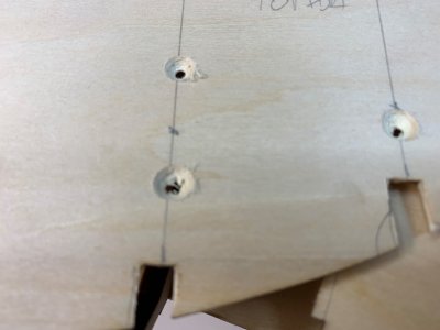
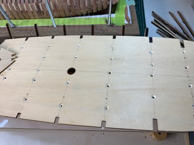
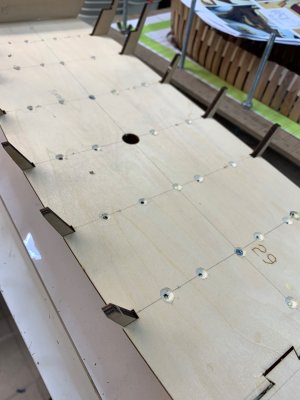
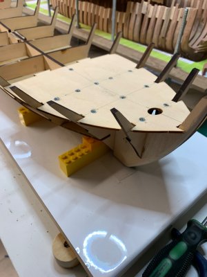
Layer of glue was applied to frames and deck, and after fitting process, deck is installed. Here you need to tweak it a bit to make it sit properly.. Screws were added using hand screwdriver, not power drill…
Before adding a “main” deck, the reinforcement #15 has to added. This is one of the steps not covered in manual so pay attention to all included pictures and make your own order of installation.
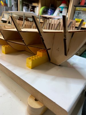
So, lets check the curvature of a deck..
Looks ok…
Some of the predrilled holes were not quote on the spot so i have to add few more, this time using trusty Dewalt drill;
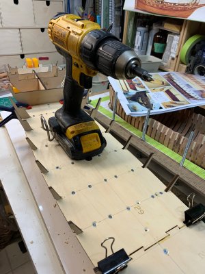
Very few screws were missed frame so they are not fully flush with the surface, so a bit of sanding/filling will be needed.
Now, i am at the stage to start planking cabine area so need to decide on the final wood for deck planking, colour, etc..
Happy modelling..


Layer of glue was applied to frames and deck, and after fitting process, deck is installed. Here you need to tweak it a bit to make it sit properly.. Screws were added using hand screwdriver, not power drill…

Before adding a “main” deck, the reinforcement #15 has to added. This is one of the steps not covered in manual so pay attention to all included pictures and make your own order of installation.

So, lets check the curvature of a deck..

Looks ok…
Some of the predrilled holes were not quote on the spot so i have to add few more, this time using trusty Dewalt drill;

Very few screws were missed frame so they are not fully flush with the surface, so a bit of sanding/filling will be needed.
Now, i am at the stage to start planking cabine area so need to decide on the final wood for deck planking, colour, etc..
Happy modelling..
You're making great progress. I love the shape of the ship, the curved and elegant hull, you can already see it.
Good afternoon. I like it. I did a couple of nails on my Xebec and I had some issues(small ones) later, so it is worth it to get this spot on. Nice. Cheers GrantWorking on a deck structure…. The curvature of a deck has to be preserved so i decided to use small screws to fix the deck to the frames. Think will be working better than nails, particularly since frames are 5mm tick so plenty of meat for a screw. First i marked down locations of holes then drilled a pilot holes that will make the screws flush once they are added..
View attachment 505260
View attachment 505258
View attachment 505256
View attachment 505259
Layer of glue was applied to frames and deck, and after fitting process, deck is installed. Here you need to tweak it a bit to make it sit properly.. Screws were added using hand screwdriver, not power drill…
View attachment 505262
Before adding a “main” deck, the reinforcement #15 has to added. This is one of the steps not covered in manual so pay attention to all included pictures and make your own order of installation.
View attachment 505261
So, lets check the curvature of a deck..
View attachment 505257
Looks ok…
Some of the predrilled holes were not quote on the spot so i have to add few more, this time using trusty Dewalt drill;
View attachment 505255
Very few screws were missed frame so they are not fully flush with the surface, so a bit of sanding/filling will be needed.
Now, i am at the stage to start planking cabine area so need to decide on the final wood for deck planking, colour, etc..
Happy modelling..
Thank you; I was thinking of nails but decided to go with screws just because the curvature of the ship is very important and cannot afford some nails giving up after a while. The deck wood is strong and need good amount of nails to keep it in correct place..Good afternoon. I like it. I did a couple of nails on my Xebec and I had some issues(small ones) later, so it is worth it to get this spot on. Nice. Cheers Grant
Cheers
Thank you; yeah I like the shape as well as this is one of my favourite models..You're making great progress. I love the shape of the ship, the curved and elegant hull, you can already see it.
Cheers
Nice work. I’ll be sitting quietly in the back row…
I do have a question though, do your kids (or grandkids) know you raided their LEGO kits?

I do have a question though, do your kids (or grandkids) know you raided their LEGO kits?

The ingenious idea with the screws, now I can rest assured the climate will not affect the model. 
I fought hard, first time I had to bribe them for a few test blocks, then purchased my own set, from brickworld, just bricks I think I will need and now keep them in a safe spot, away from their praying eyesNice work. I’ll be sitting quietly in the back row…
I do have a question though, do your kids (or grandkids) know you raided their LEGO kits?

Below is Lego Titanic, next to my fregate Phoenix, just to show what kind of fight I have to go thru borrowing few blocks
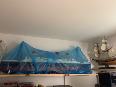
Happy modelling..
Yup, no more excuses for faulty deck, specifically in rainy place like Vancouver..The ingenious idea with the screws, now I can rest assured the climate will not affect the model.
Continue work on model by adding two parts (#21) which do require a mix of CA and white glue just because part #21 might need a bit sanding since frames are very tight and clamps needs too keep them together while drying…
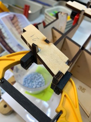
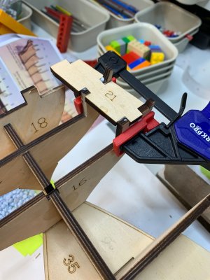
Frame #18 needed to be removed from the keel with a bit of acetone… and other part glued first; then it will be put back on keel and attached to #21..
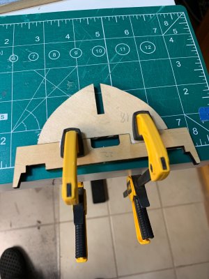
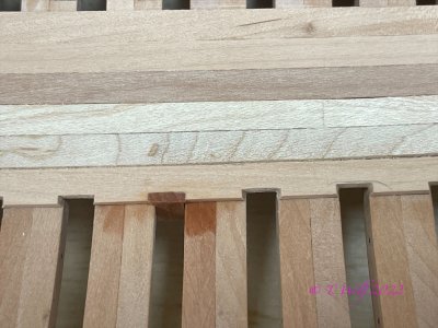
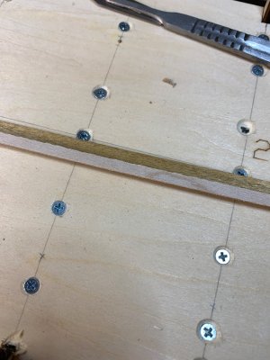
Now, i am thinking of deck planking… kit provided golden teak veneer does not quite fit my liking for deck planking, colour wide as well as width; the width is close to 5mm which looks a bit oversized to me for this ship.
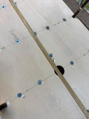
I put, as a test, a maple plank, 1x4mm and looks better to me then teak. Not sure how maple plank will handle other part of building, like scraping, oil, etc… any experience you guys might have with maple planking would be appreciated. I am leaning towards castello for deck since i like its colour and appearance.
Happy modelling..


Frame #18 needed to be removed from the keel with a bit of acetone… and other part glued first; then it will be put back on keel and attached to #21..

Now, i am thinking of deck planking… kit provided golden teak veneer does not quite fit my liking for deck planking, colour wide as well as width; the width is close to 5mm which looks a bit oversized to me for this ship.

I put, as a test, a maple plank, 1x4mm and looks better to me then teak. Not sure how maple plank will handle other part of building, like scraping, oil, etc… any experience you guys might have with maple planking would be appreciated. I am leaning towards castello for deck since i like its colour and appearance.

Happy modelling..
Thank you Tobias.Maple is quite easy to scratch as long as you work in the right direction with the grain, as is the case with all types of wood. It is a little softer than pear.
View attachment 505687
A picture of La Palme, it also harmonizes well with pear or serviceberry (Swiss pear)
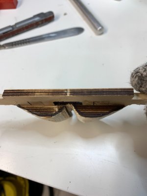
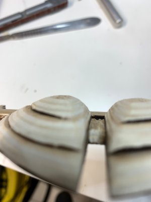
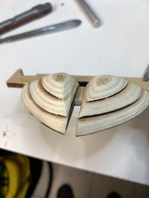
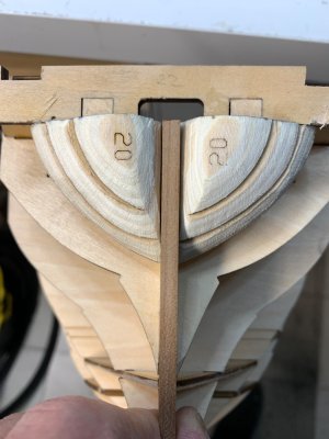
Continue with stern carving, very interesting shape… and not covered in the manual as it supposed to be since it is a challenging part… there are some pictures in manual of the curvature that needs to be achieved. Good thing is that some build logs are also available, showing this area in a bit more details but would expect a bit more from a manual. Anyhow, parts are removed and glued to #18.
I was thinking to carve it without being glued to #18 but decided to glue it anyway to the #18 frame. I think it is a bit easier..
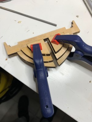
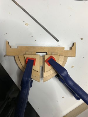
Then i marked the curvature that needs to be carved..
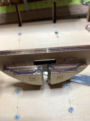
And lets start…
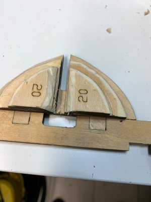
Curvature has been traced on parts ..
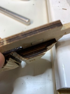
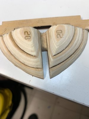
Continue tomorrow, it is getting to late..
Happy modelling..
I was thinking to carve it without being glued to #18 but decided to glue it anyway to the #18 frame. I think it is a bit easier..


Then i marked the curvature that needs to be carved..

And lets start…

Curvature has been traced on parts ..


Continue tomorrow, it is getting to late..
Happy modelling..


