
Thanks for the kind wishes. I am not working on a build at this time. Hoping to start one in 2021.Hallo Barry alias @Barry1
definitely today you are number 1
we wish you all the BEST and a HAPPY BIRTHDAY
PS: Are you working in moment on an actual project?

-

SUBSCRIBE TO SHIPS IN SCALE TODAY!
The beloved Ships in Scale Magazine is back and charting a new course for 2026!
Discover new skills, new techniques, and new inspirations in every issue.
NOTE THAT OUR NEXT ISSUE WILL BE MARCH/APRIL 2026 -

Win a Free Custom Engraved Brass Coin!!!
As a way to introduce our brass coins to the community, we will raffle off a free coin during the month of August. Follow link ABOVE for instructions for entering.
- Home
- Forums
- Ships of Scale Build Logs
- Super Detailing Static Models / Other Genres
- Historical Trailways, Guns, Aircraft, and Cars
You are using an out of date browser. It may not display this or other websites correctly.
You should upgrade or use an alternative browser.
You should upgrade or use an alternative browser.
Thanks!!!Happy Birthday, Barry!Enjoy your special day!
- Joined
- Jan 6, 2021
- Messages
- 16
- Points
- 8

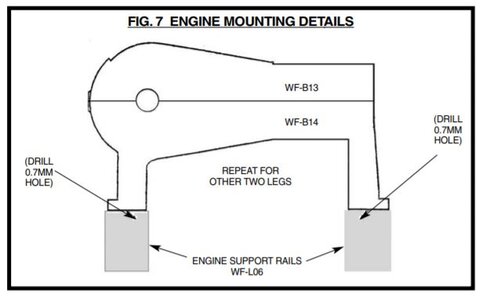
Can someone pls help me here: The instructions tell me to drill holes in the bottom four "feet" of the engine block and also holes in the engine mounting logs....but they don't say why. I called Model Airways. The very nice guy who works there said "I have no idea either". Who can tell me why I'm drilling these holes and how far fore or aft does the engine get mounted? Great model kit. CRUMMY instructions. Brian Amato, Traverse City, Michgian

Hallo Brian alias @Brian AmatoCan someone pls help me here: The instructions tell me to drill holes in the bottom four "feet" of the engine block and also holes in the engine mounting logs....but they don't say why. I called Model Airways. The very nice guy who works there said "I have no idea either". Who can tell me why I'm drilling these holes and how far fore or aft does the engine get mounted? Great model kit. CRUMMY instructions. Brian Amato, Traverse City, Michgian
first of all a warm welcome here on board of our forum.
I hope, that @Barry1 or somebody else knowning this kit is reading this post and is able to help..... I am crossing the fingers
- Joined
- Jan 6, 2021
- Messages
- 16
- Points
- 8
Thanks for the warm welcome ")
- Joined
- Dec 31, 2018
- Messages
- 20
- Points
- 58
Brian,Can someone pls help me here: The instructions tell me to drill holes in the bottom four "feet" of the engine block and also holes in the engine mounting logs....but they don't say why. I called Model Airways. The very nice guy who works there said "I have no idea either". Who can tell me why I'm drilling these holes and how far fore or aft does the engine get mounted? Great model kit. CRUMMY instructions. Brian Amato, Traverse City, Michgian
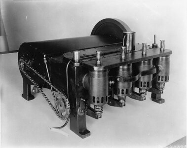
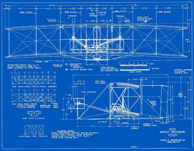
The two drawing are in the instructions and the photo of the engine used in the Flyer. The "feet" are what the engine rests and are used to attache the engine to the wooden mount ("logs") that is part of the wing structure. drill out the lugs on the engine and match drill in the correct location/orientation on the engine mounts. I'm guessing there is hardware provided to install the engine.
This build thread has a lot of helpful photos including the engine installation the should be of some help.

1/16 Model Airways Wright Flyer
Here are some pics of the Wright Flyer. This build reminds me a whole lot of building r/c planes. The details and parts are amazing. I haven’t veared from the instructions other than some wood stain. It probably would have looked great being entirely the lighter color, but I like the ribs detail...
 cs.finescale.com
Regards,
John McMakin
Attachments
- Joined
- Jan 6, 2021
- Messages
- 16
- Points
- 8
Thanks for all the help folks. Still no fore and aft dimension for mounting the engine to be found. Guess just wait until I'm far enough along to line up the engine/chains with the props and that should locate the engine.
- Joined
- Jan 6, 2021
- Messages
- 16
- Points
- 8
Thanks JMac !!

From what I recall seeing this Wright last Fall it is a delicate piece of work and rigging leading to a very accurate Flyer, RichThanks JMac !!
- Joined
- Jan 6, 2021
- Messages
- 16
- Points
- 8
I see some Navy "crows" on these pages. Who's Navy?That looks like a great kit. I have a Sopwith Pup on the shelf awaiting assembly. I look forward to your build.
Served aboard USS ESSEX CVS-9, 1960 - 1964. MM2 in "B" Division. Worked in the Evaporators, berthed with the guys from the "Oil & Water" gang.
Great ship, great crew. "THE OLDEST AND THE BOLDEST"
The "Crows you see at the bottom left are the rankings on this forum site. Any "Crows" you see on the TOP left are avitars, and these people may be NAVY.
EJ
Great ship, great crew. "THE OLDEST AND THE BOLDEST"
The "Crows you see at the bottom left are the rankings on this forum site. Any "Crows" you see on the TOP left are avitars, and these people may be NAVY.
EJ
No "crow" but an airdale served with Heavy Attack Reconnaissance Squadrons out of NAS Sanford in the middle '60s deploying aboard the Independence, Saratoga, and Ranger in Tonkin Gulf Yankee Station (Yankee Station Yacht Club!) Rich (PT-2) my E-5 rating as a photo interpreter.I see some Navy "crows" on these pages. Who's Navy?
- Joined
- Jan 6, 2021
- Messages
- 16
- Points
- 8
thanks for serving. I was a brown shoe. ASW squadron - VP-21 out of Brunswick, Maine, flying P2V7s. I was the photo intelligence kid taking pictures of Russian Subs and Freighters. 1967-1970Served aboard USS ESSEX CVS-9, 1960 - 1964. MM2 in "B" Division. Worked in the Evaporators, berthed with the guys from the "Oil & Water" gang.
Great ship, great crew. "THE OLDEST AND THE BOLDEST"
The "Crows you see at the bottom left are the rankings on this forum site. Any "Crows" you see on the TOP left are avitars, and these people may be NAVY.
EJ
- Joined
- Jan 6, 2021
- Messages
- 16
- Points
- 8
Hey guys. I'm starting the assembly of the engine on the Wright Flyer and can't find the crankshaft. I don't find it among the cast Britania metal parts. I'm beginning to think it's something I'm supposed to make out of brass tubing. Is that right? Couldn't they just say "WP-126 to made by the builder" or something like that? Am I right in this? How do I know how long to make it? Thanks in advance.
- Joined
- Jan 6, 2021
- Messages
- 16
- Points
- 8
Hey guys. I'm starting the assembly of the engine on the Wright Flyer and can't find the crankshaft. I don't find it among the cast Britania metal parts. I'm beginning to think it's something I'm supposed to make out of brass tubing. Is that right? Couldn't they just say "WP-126 to be made by the builder" or something like that? Am I right in this? How do I know how long to make it? Thanks in advance.Brian,
The two drawing are in the instructions and the photo of the engine used in the Flyer. The "feet" are what the engine rests and are used to attache the engine to the wooden mount ("logs") that is part of the wing structure. drill out the lugs on the engine and match drill in the correct location/orientation on the engine mounts. I'm guessing there is hardware provided to install the engine.
This build thread has a lot of helpful photos including the engine installation the should be of some help.
1/16 Model Airways Wright Flyer
Here are some pics of the Wright Flyer. This build reminds me a whole lot of building r/c planes. The details and parts are amazing. I haven’t veared from the instructions other than some wood stain. It probably would have looked great being entirely the lighter color, but I like the ribs detail...
Regards,
John McMakin
Brian, sorry to be late in replying. I built this model back in 2019 and I must admit it’s a bit of a challenge to remember the details. I did not drill any holes in the engine block. I chose to secure the engine block using epoxy. This was more than sufficient. The challenge to me with the engine assembly was getting the chain supports and chain line installed.
good luck on your build.
good luck on your build.
- Joined
- Jan 6, 2021
- Messages
- 16
- Points
- 8
I was a photo interpreter (PT) in ASW at NAS Brunswick flying in P2s. I was the kid hanging out the after station window photographing Russian Subs and Freighters.No "crow" but an airdale served with Heavy Attack Reconnaissance Squadrons out of NAS Sanford in the middle '60s deploying aboard the Independence, Saratoga, and Ranger in Tonkin Gulf Yankee Station (Yankee Station Yacht Club!) Rich (PT-2) my E-5 rating as a photo interpreter.
- Joined
- Jan 6, 2021
- Messages
- 16
- Points
- 8
Barry....what the heck is the crankshaft made out of? I kept looking for a pre-formed (Britania) crank until I finally found a footnote or addendum that said something about a change in part number nomenclature being 1/32 brass tubing. Is the crank something the builder is supposed to fab out of tubing? What length? Doesn't say anywhere. Maybe, as we used to say in the Navy "Hammer to fit...paint to match"Worked on the engine and magneto yesterday. Lots of very small and delicate parts to this kit. I have decided to paint all the engine and drive train related parts black based on the display of the Wright Flyer at the Smithsonian. I was recently able to visit the Air and Space Museum and found lots of good detail and ideas for the plane. More on that later.
I also assembled the jig to be used to assembleView attachment 101516 the plane. I jig holds the top and bottom wing so you can more easily add the struts and wires.
View attachment 101518