Naseby 1655 - reverse engineering the ship model

As for deadrise, indeed, it is directly related to stability. The best known examples of large ships with extreme deadrise are probably the Symond's designs. Excellent sailing ships, but hopeless gun platforms.
Let us not delve into the performance comparison of specially designed ships with high deadrise (or we will end up discussing Symonds and Forfait, which is totally out of scope here). :)

What I meant to say is that there was (I am not sure how common, but it certainly existed) a method of adding deadrise to, let's say, otherwise traditional designs specifically to increase performance, which may have been proposed by Sheldon as one of the modifications to the design he brought from England during the design phase of the Riskäpplet, and so it is possible the deadrise we see on the model is intended to be there. This may, by the way, account for discrepancies in depth-in-hold measurements in some way.
 
Last edited:
.​

Yes, it also occurred to me that the higher deadrise could have been the result of some deliberate modification during Sheldon's arrangements with the Swedish, but how to demonstrate this? Besides, this would be rather contrary to Baltic conditions featuring shallow waters. Remember David Balfour's design drawing of the Danish ship Hummeren 1623, designed precisely for Baltic specifics? Flat as a pancake. In that sense, the 'Dutch' proportions/shapes had it easier there. :)

.​
 
Last edited:
.​

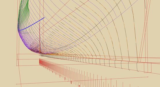
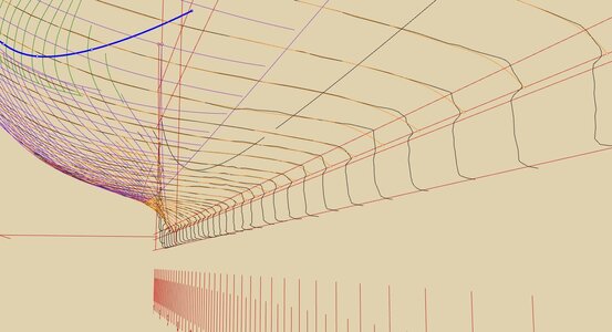
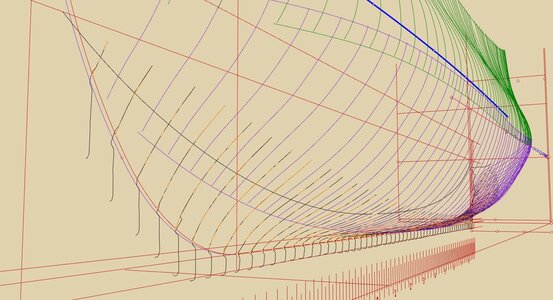
Following Fred's advice, which I picked up even more generally, I try to interpret as little as possible, at least for now. For example, the graphics below show a comparison between the 3D model intersection lines (black lines) and the hand-corrected, already smooth lines (orange lines). This is shown for the lowest, floor section only, and separately for the stern, the midship and the bow area. As can be seen, the only major deviations are in the middle/midship section close to the keel, where the modeller exaggerated the sanding, in my opinion.

ViewCapture20230501_151033.jpg

ViewCapture20230501_151144.jpg

ViewCapture20230501_150742.jpg

.​
 
Last edited:
As can be seen, the only major deviations are in the middle/midship section close to the keel, where the modeller exaggerated the sanding, in my opinion.

Yes, I can see what you mean by sanding irregularities now.

Yes, it also occurred to me that the higher deadrise could have been the result of some deliberate modification during Sheldon's arrangements with the Swedish, but how to demonstrate this?

There are some ways I can think of, but let's see what the model reveals first.

It's also a possibility that the Naseby also could have had this modification over the original 1654 lines.

Besides, this would be rather contrary to Baltic conditions featuring shallow waters. Remember David Balfour's design drawing of the Danish ship Hummeren 1623, designed precisely for Baltic specifics? Flat as a pancake.

Well, they did seem to opt for the overall smaller-dimensions ship in the end. And wrecked her on a rock.

And I have a certain suspicion that the Swedish Navy had more than their share of flat bottoms with Vasa.
 
Last edited:
Dear Waldemar,

Thus far I have found your analysis captivating with the amount of detail being put into it.
Great investigative work and analysis.

However, please excuse my novice question(s) and comments as this is a new field for me.
But why do you feel the model was over sanded?
Is the deviation the same on both sides of the model?

Couldn't it have been deliberate?
To my untrained eye they may have wanted a flatter surface in that area of the ship.
Possibly traditionally it may have been a smooth curve, but they may have had other reason's for this i.e. fitting, sealing, buoyancy issues, stabilization etc.
Recall this was an era of experimentation and testing out of new theories - which were sometimes not scientifically based.

I doubt the original master modeler would not have been cognizant that he was over sanding that area.
These gentlemen were masters at their trade just like many of the craftsmen of that era - thus my inclination is not to write it off as an error so hastily.
It may be a newly discovered remnant to a new proposal during the course of their deliberations of the proposed ship design.

Also, is it possible that this model represents two different design concepts within the same model thus saving time and money?
Thus why there are discrepancies from the port to starboard sides of the model ship.
 
@Allegheny ,

Please take a look here:

1682963650752.png

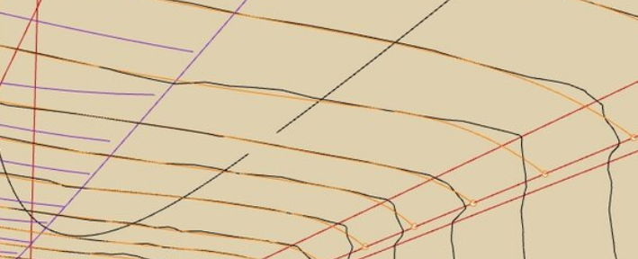
This is definitely a trace of rough treatment of the frames and since it is very different from one frame to the other. Furthermore, do not forget that on the real ship the frames are covered in planking, and it would negate any small differences.

Also take into account that most probably this model was a working model, involved in discussions of the ship's design, not a decorative one.

There indeed are models that did represent two variants of a design on different sides, but by general convention, they have those sides distinctly and differently decorated. The difference we observe on the model is more consistent with shrinking wood than anything else.
 
Last edited:
@Allegheny ,

Please take a look here:

View attachment 372321

This is definitely a trace of rough treatment of the frames and since it is very different from one frame to the other. Furthermore, do not forget that on the real ship the frames are covered in planking, and it would negate any small differences.

There indeed are models that did represent two variants of a design on different sides, but by general convention, they have those sides distinctly and differently decorated. The difference we observe on the model is more consistent with shrinking wood than anything else.
Thank you very much Martes for responding to my questions.
As I noted I'm still drinking from the proverbial firehose and the engineer in me likes to beg questions and look at issues with an alternative mindset.
 
It all goes to speed vs. quality in the end.
There is a difference between "knock me a demonstration framing for the board meeting next week" and a model of Victory of 1744 that wasn't complete by the time the ship was built, launched, commissioned and lost, and I am not sure if it was in time for the inquiry commission. :)

By the looks of it, this model is closer to the first case.
 
.​

Exactly as Martes wrote. I drew my conclusions mainly from the irregular shape of these parts. If anyone does manual work, they know how easy it is to have a similar mish-mash. It happens even to masters, and even more easily to their journeymen and apprentices. Then, in order to visually disguise it, the other side is usually 'corrected' in the same way. There is really no reason to come up with highly improbable theories. The simplest and most obvious explanations are almost always correct.

.​
 
Very interesting work Waldemar.
It would be fantastic if your research leads to a set of drawings for fellow modellers.
The mentioned book of Niklas Eriksson is also very interesting and I can highly recommend it, unfortunately only in Swedish. A combination of your research and the wreck information of Niklas Eriksson can be at the base of a fantastic model build using contemporary sources.

Keep the updates coming looking forward to them.

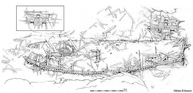
Guess you are familiar with the documented wreck of Riksapplet as documented by Niklas Eriksson.
1600px-Riksäpplet_Niklas_Eriksson.jpg
 
.​

Thank you very much Maarten. Indeed, Eriksson has published some very interesting work on Riksäpplet 1663 in 2017–2019 (also in English). However, there has not been as comprehensive an archaeological survey as for example for Mary Rose 1545 or Vasa 1628, so the structural and conceptual aspects of the ship are still to be worked out (at least to my knowledge). To be honest, I doubt they would be carried out, as they would require an enormous amount of work, time and money, and there are, after all, dozens and hundreds of other equally interesting shipwrecks on the bottom of the Baltic Sea. In this context, this model becomes even more important.

Niklas Eriksson, The ship Riksäpplet and the introduction of English naval architecture in Sweden in the 17th century, Post-Medieval Archaeology 2017
Niklas Eriksson, Riksäpplet. Arkeologiska perspektiv på ett bortglömt regalskepp, 2017
Niklas Eriksson, Riksäpplet (1676) resurrecting a neglected wreck, Symposium paper: Baltic and beyond. Change and continuity in shipbuilding 2015 (2017)
Niklas Eriksson, Riksäpplet – regalskeppet mitt i Stockholms skärgård, MT 1/2019 (the content as above)

* * *​

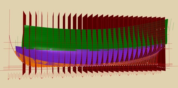
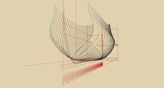
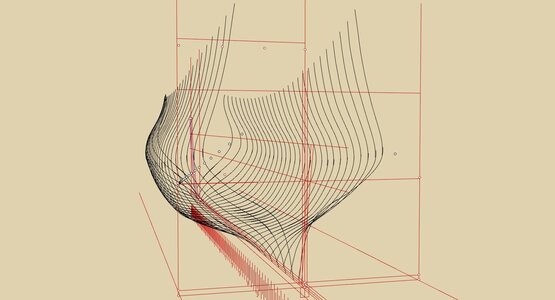
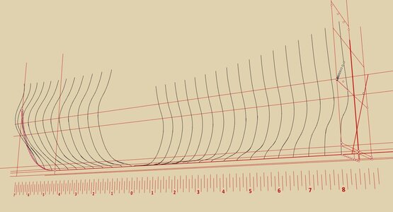
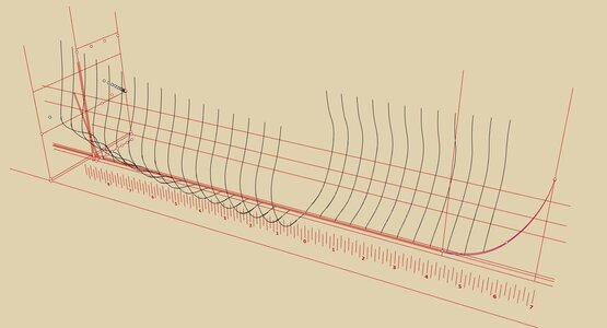
I have just completed the preparatory stage. The three separate hull surfaces (floor, futtock, toptimber) have been cut with common planes, every second station (so as not to get lost in the clutter of lines), and only now does the real game begin...

ViewCapture20230502_071859.jpg

ViewCapture20230502_072248.jpg

ViewCapture20230502_072329.jpg

ViewCapture20230502_072611.jpg

ViewCapture20230502_072709.jpg

.​
 
Last edited:
.​

Ah, yes, indeed, I did not elaborate on this earlier. After importing the 3D model (OBJ) into Rhino, I made adjustments to its shape by rotations, twists and bends, mostly of a local nature, to get it at least approximately symmetrical. The reference lines were the keel (at the bottom) and the masts and capstan (at the top). Just as few of these treatments as were absolutely necessary.

In the second stage of shape correction (the initial straightening was still not perfect), I laterally shifted some of the hull intersection lines, mainly at the bow and stern, aligning them with the keel, which I defined as having an equal width throughout. I realize that both the real ships and this model have a slightly tapered keel, but in the tracing process in the shipyard this has not yet had to be taken into account. Even more important, the differences are minimal, and defining tapered keel would unnecessarily complicate the 3D model without significant benefit. Anyway, I will remember this slight difference when fitting the supposed design curves.

Finally I decided to use only the left half. The right half was discarded as being more irregular and shrunken.

In fact, I now have two significant problems to solve. The first is to find the longitudinal position of the master frame. The issue is that the maximum breadth is in a different place at the level of the wales, and in a significantly different place in the lower parts of the hull (by about 4–6 timber&room intervals).

The second dilemma that now needs to be resolved is the overall breadth of the hull. Admittedly, the difference to Naseby's full 42ft is only about 2.5–3 mm at this scale, but in practice this makes quite a difference to the precise fitting of the supposed design lines, which you are certainly aware of. Be that as it may, I will point to it later, when hopefully this become more clear.

.​
 
Last edited:
ViewCapture20230502_072329.jpg

I definitely, definitely love this shape.
 
In fact, I now have two significant problems to solve. The first is to find the longitudinal position of the master frame. The issue is that the maximum breadth is in a different place at the level of the wales, and in a significantly different place in the lower parts of the hull (by about 4–6 timber&room intervals).

Can't say without seeing your current state of the model, but my general impression until now is not to trust the wales level.
 
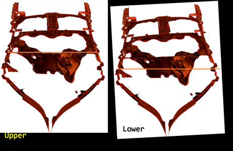
Sorry for the sidetrack, but what kind of image is this? It looks like someone dribbled blood on the page :)
In this case the 3d model has been created by stitching together a quantity of 2d photos. A normal camera does not penetrate wood, so the internal deck structure is recreated noisy from pixels got from the inside through various openings in the outer surface.
 
Possibly @fred.hocker could shed light on whether there are any known drawings, photos of the interior or x-rays/magnetic resonance imaging (mri) of the model that could be shared. If so I would imagine it would help your analysis significantly. He may have more available information given the access he has had to the model.
 
.​

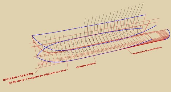
The first finding of which I am already quite certain, i.e. the shape and position of the line of greatest breadth.

In the aft part of the hull it is a curve obtained with the very popular mezza luna 'device'. In the fore part, a solution very typical of English shipwrights of this period was employed, consisting of two arcs of a circle. It is a practical way giving good results, but less elegant than, e.g. the one-piece logarithmic curve already used on the Continent. With this method, it was also necessary to make a sketch in advance of this two-part curve on paper in order to get coordinates for tracing the frames on the mould loft in the yard. Needless to say, huge up-scaling and the transfer itself introduced inevitable errors, unless they were calculated arithmetically, which was only possible for the better educated shipwrights.

These two parts, fore and stern, are connected by a straight section of a length of 16 timber&room intervals. The master frame falls almost perfectly at 1/3 of the keel length.

Note: this is not of great conceptual importance, but it should be added here that the arc of the circle, which is marked in the diagram as having 130.49 feet radius, should be slightly flatter for perfect conformity with the model. However, if this is the case, this arc loses tangency with the adjacent curves and the resulting hull surfaces will not be smooth but will have slight kinks/creases. This has indeed been the case in practice then, and it also makes this method of two arcs not elegant in a design sense.

ViewCapture20230503_001048.jpg

ViewCapture20230503_001150.jpg

.​
 
Last edited:
Guys, I'm really enjoying the research, drawings and history of this ship. Looking forward to the final design and of course the actual model. Magic Mike
 
Back
Top