-

Win a Free Custom Engraved Brass Coin!!!
As a way to introduce our brass coins to the community, we will raffle off a free coin during the month of August. Follow link ABOVE for instructions for entering.
-

PRE-ORDER SHIPS IN SCALE TODAY!
The beloved Ships in Scale Magazine is back and charting a new course for 2026!
Discover new skills, new techniques, and new inspirations in every issue.
NOTE THAT OUR FIRST ISSUE WILL BE JAN/FEB 2026
You are using an out of date browser. It may not display this or other websites correctly.
You should upgrade or use an alternative browser.
You should upgrade or use an alternative browser.
Naseby 1655 - reverse engineering the ship model
- Thread starter -Waldemar-
- Start date
- Watchers 27
-
- Tags
- naseby 1655
.
Adminitrators, can I ask you to increase the resolution of the inserted images? Also for non-registered (not logged in) people. Around 1600 dpi for bitmap widths would be ideal. What do you guys think about this?
.
Hi Waldemar,.
Adminitrators, can I ask you to increase the resolution of the inserted images? Also for non-registered (not logged in) people. Around 1600 dpi for bitmap widths would be ideal. What do you guys think about this?
.
I think the current resolution of pictures and files has to do with the storage capacity of the site on the server space.
Maybe an idea to add an additional link to a site where you can store high resolution files and people can download.
@Donnie, @zoly99sask guess you have more insight in this server related topics.
Waldemar,
Well, there are several moving parts to answer here. However, in this short explanation, I want to get back on topic again after this post.
1) the software that we are using automatically compresses the image file you are uploading. The final size is usually around 195k to 200k and the image "size" is limited to about 1400 x 1200. We feel that this is more than adequate for posting images and should deliver a posted image within a good balance.
2) we do have the forum set up to where the "Guest" usually only sees the thumbnails. This should encourage people to register and join so that they can participate.
3) Using an example image of post #41, you can click on the image and it will open a new browser window. When you mouse over the image, will open up a slightly larger image. Therefore, I right-click and "saved as" to my PC which the image is exactly 195K and pixel size is 1339 x 1222 (which is close to the 1400 x 1200) that I stated earlier. Now, to go further with this, I opened that image into my Corel Paint Shop Ultimate and I "resized" the image to 5000 x 3055 and it produced a file size of 1.7 Meg. Still, the image retained as far as I could tell hardly any artifacts.
4) Yes, BMP files contain large, raw, high-quality images, which makes them better for editing. JPEG files automatically compress, so they're generally smaller and of lower quality. I assume (and have never tried) to upload a BMP file, but I am sure that the forum software will still compress it down to 200k and 1400 x 1200 pixels.
5) lastly, you can also research that there are image converters that can take an image and convert it to a VECTOR image which is almost nearly immune to resizing.
6) another reason for the size of image files that you see here on the forum:
- is that not everyone has high-speed internet.
- allowing for larger files, yes, does mean more storage and more yearly cost to add storage.
.
Thank you very much for your replies on this matter. I was a bit perplexed myself and actually expected such explanations and decisions, but I had to at least try. Thanks again.
.
What a coincidence!
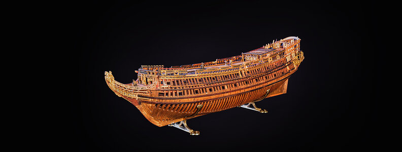
That we too have been working on this projekt since 2018. My husband Dr. Kroum Batchvarov - Professor of Underwater Ship Archaeologi and me. It really isn’t Naseby... We did photogrammetry with high resolution photos to make a 3D model. Now I am working on the lines drawings, while my husband is writing the research part!
That we too have been working on this projekt since 2018. My husband Dr. Kroum Batchvarov - Professor of Underwater Ship Archaeologi and me. It really isn’t Naseby... We did photogrammetry with high resolution photos to make a 3D model. Now I am working on the lines drawings, while my husband is writing the research part!

Hi Olga,What a coincidence!
That we too have been working on this projekt since 2018. My husband Dr. Kroum Batchvarov - Professor of Underwater Ship Archaeologi and me. It really isn’t Naseby... We did photogrammetry with high resolution photos to make a 3D model. Now I am working on the lines drawings, while my husband is writing the research part!
View attachment 372653
Great to hear this info, will you be publishing this research? All this info will make a great book for all our libraries.
- Joined
- Nov 10, 2018
- Messages
- 5
- Points
- 43

Serves me right for dragging my feet with my work on the model. I ought to have published it long ago! Waldemar's work is interesting and is along the lines of what I have been doing. Thank you for sharing it!
While I worked at Vasa Museum, I was the one who requested SMM to dig the model out of storage. It was hidden in a plywood box, in a storage cave, covered with modern garbage such as fishing nets, buoys, life buoys, etc. Fred requested the loan of the model and it sat on my desk during the time I was there. Fred and I did a FaroArm recording of the model then (2011!) and in 2018 my wife Olha Batchvarov and I did a photogrammetry. I have built the 3D-model and now she is working on the lines. I was not aware of the scan on Sketchup.
Niklas Eriksson and I are working on a joint article about this model and its reverse-engineering. Nothing, absolutely nothing in this model suggests that it is of Naseby. As early as 1980, in his book Great Ships, Frank Fox who was one of the foremost scholars in the field of 17th century naval ships, pointed out that the model is NOT Naseby, but Rijksapplet. I concur with Mr. Fox, Fred and with Niklas on this. It has nothing to do with Naseby, beyond Sheldon having allegedly worked on her construction. We have enough images of Naseby thanks to the van de Veldes to know what she looked like. We know the distribution of guns for both ships. We know the decoration and shape of the galleries. We know the deck arrangement of Naseby, and it does not match that of the model. I am aware of only one drawing that shows similar deck arrangement to the that of the model and it pre-dates Naseby by good 20 years. Furthermore, the Model does not have a forecastle, the Naseby did have one. The model has archaic features that were not present on Naseby (see above). The armament and distribution of gunports differs, as Niklas, Fox and Glete pointed out. The surviving shape of the galleries on the model do not match Naseby - as Fox himself pointed out to me in our correspondence. The dimensions of the model do not match Naseby's. I am perfectly satisfied that the model does NOT represent Naseby, no matter how disappointed the Naseby enthusiasts are. I also fully understand that no matter how much data one brings to bear on this issue, the Naseby enthusiasts will stick to their guns and beliefs. Incidentally, I personally would refer to her as Royal Charles, of course, being a Cavalier at heart .
.
I am an archaeologist so for me is important what the data actually shows, rather than what I want it to show me. My interest is not related to shipmodeling, but to archaeology and what we can learn about shipbuilding in this period from the model. Thus, I have no horse in this race: I do not care which vessel it represents. Either is of interest to me and my research on 17th century shipbuilding. However, there just isn't any evidence to support identifying the model as Naseby and lots to identify it with Rijks Applet. (Yes, I know it is spelled with umlaut, but I do not have it on my keyboard). So unless and until archival material tells me differently, to me this ship is not Royal Charles, aka Naseby.
Cheers,
Kroum
While I worked at Vasa Museum, I was the one who requested SMM to dig the model out of storage. It was hidden in a plywood box, in a storage cave, covered with modern garbage such as fishing nets, buoys, life buoys, etc. Fred requested the loan of the model and it sat on my desk during the time I was there. Fred and I did a FaroArm recording of the model then (2011!) and in 2018 my wife Olha Batchvarov and I did a photogrammetry. I have built the 3D-model and now she is working on the lines. I was not aware of the scan on Sketchup.
Niklas Eriksson and I are working on a joint article about this model and its reverse-engineering. Nothing, absolutely nothing in this model suggests that it is of Naseby. As early as 1980, in his book Great Ships, Frank Fox who was one of the foremost scholars in the field of 17th century naval ships, pointed out that the model is NOT Naseby, but Rijksapplet. I concur with Mr. Fox, Fred and with Niklas on this. It has nothing to do with Naseby, beyond Sheldon having allegedly worked on her construction. We have enough images of Naseby thanks to the van de Veldes to know what she looked like. We know the distribution of guns for both ships. We know the decoration and shape of the galleries. We know the deck arrangement of Naseby, and it does not match that of the model. I am aware of only one drawing that shows similar deck arrangement to the that of the model and it pre-dates Naseby by good 20 years. Furthermore, the Model does not have a forecastle, the Naseby did have one. The model has archaic features that were not present on Naseby (see above). The armament and distribution of gunports differs, as Niklas, Fox and Glete pointed out. The surviving shape of the galleries on the model do not match Naseby - as Fox himself pointed out to me in our correspondence. The dimensions of the model do not match Naseby's. I am perfectly satisfied that the model does NOT represent Naseby, no matter how disappointed the Naseby enthusiasts are. I also fully understand that no matter how much data one brings to bear on this issue, the Naseby enthusiasts will stick to their guns and beliefs. Incidentally, I personally would refer to her as Royal Charles, of course, being a Cavalier at heart
I am an archaeologist so for me is important what the data actually shows, rather than what I want it to show me. My interest is not related to shipmodeling, but to archaeology and what we can learn about shipbuilding in this period from the model. Thus, I have no horse in this race: I do not care which vessel it represents. Either is of interest to me and my research on 17th century shipbuilding. However, there just isn't any evidence to support identifying the model as Naseby and lots to identify it with Rijks Applet. (Yes, I know it is spelled with umlaut, but I do not have it on my keyboard). So unless and until archival material tells me differently, to me this ship is not Royal Charles, aka Naseby.
Cheers,
Kroum
- Joined
- Nov 10, 2018
- Messages
- 5
- Points
- 43

The deadrise on the model most definitely was intended to be there! There is no room for doubt there. It is part of the design feature, there are explanations in contemporary treatises how to do this.Let us not delve into the performance comparison of specially designed ships with high deadrise (or we will end up discussing Symonds and Forfait, which is totally out of scope here).
What I meant to say is that there was (I am not sure how common, but it certainly existed) a method of adding deadrise to, let's say, otherwise traditional designs specifically to increase performance, which may have been proposed by Sheldon as one of the modifications to the design he brought from England during the design phase of the Riskäpplet, and so it is possible the deadrise we see on the model is intended to be there. This may, by the way, account for discrepancies in depth-in-hold measurements in some way.
This has absolutely nothing to do with the depth in hold measurement, as that is taken in the hold - just what it says on the tin. It would influence the draught of the ship to some extent, but this is rarely registered in archival documents, because it varied depending on trim, loading.
Cheers
Kroum
- Joined
- Nov 10, 2018
- Messages
- 5
- Points
- 43

We actually did use a camera and videoed the interior of the model, yes.Possibly @fred.hocker could shed light on whether there are any known drawings, photos of the interior or x-rays/magnetic resonance imaging (mri) of the model that could be shared. If so I would imagine it would help your analysis significantly. He may have more available information given the access he has had to the model.
- Joined
- Nov 10, 2018
- Messages
- 5
- Points
- 43

And, the simplest explanation, as Fred pointed out, the model was found in three separate pieces. I believe the unevenness of the frames as assembled now, is thanks to that. I have not seen any evidence for "sanding" or any other deformation caused by the builder of the model, Sheldon himself. There is no evidence for two different designs mixed in the same model, either. There is evidence of relocating the cheeks (which currently are a modern addition - beginning of the 20th c) and the hawse holes. As I said elsewhere, this model sat in Fred Hocker's office for years and more specifically on my own desk while I worked there. I had the opportunity to observe it directly; not via scans or 3D models. Thus, I am quite sure that the deadrise is original feature of the model.@Allegheny ,
Please take a look here:
View attachment 372321
This is definitely a trace of rough treatment of the frames and since it is very different from one frame to the other. Furthermore, do not forget that on the real ship the frames are covered in planking, and it would negate any small differences.
Also take into account that most probably this model was a working model, involved in discussions of the ship's design, not a decorative one.
There indeed are models that did represent two variants of a design on different sides, but by general convention, they have those sides distinctly and differently decorated. The difference we observe on the model is more consistent with shrinking wood than anything else.
This is exactly what we do together with @AdmiralBenbowHi Olga,
Great to hear this info, will you be publishing this research? All this info will make a great book for all our libraries.
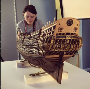
I found a photo from the museum with this model)))
Goosebumps when you realize that you are photographing a model that is over 300 years old...
Hi Kroum,
Just to let you know I have many of your articles via academia. They are excellent and written so we can understand them in layman's terms.. You and Olha make a great team. God Bless and stay safe.
Just to let you know I have many of your articles via academia. They are excellent and written so we can understand them in layman's terms.. You and Olha make a great team. God Bless and stay safe.
Last edited by a moderator:
- Joined
- Nov 4, 2020
- Messages
- 80
- Points
- 103

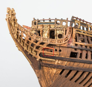
. There is evidence of relocating the cheeks (which currently are a modern addition - beginning of the 20th c) and the hawse holes.
I noticed it already and told Waldemar in private correspondence.
Port side:
Starboard side:
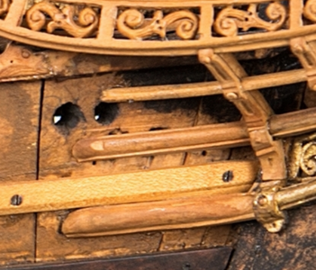
They are still somewhat asymmetric, but closer to the place where they should be.
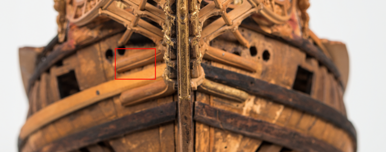
Also, some internal details obstruct the cable entry from the inside in the _new_ holes, so their place is apparently wrong.
However, there just isn't any evidence to support identifying the model as Naseby and lots to identify it with Rijks Applet.
As we explained before, that is a question of dimensions. If the dimensions of the model as we know them are correct, and we assume the scale of 1:48, the ship depicted by the model is larger than the known dimensions of Riksapplet as built. (see post #15)
However the model indeed can and probably have incorporated changes from the English original (including deadrise - if the deadrise was not already present on the original - the shape of the bow and decorations), yet I would wait for Waldemar to make at least a preliminary set of lines before looking at this more closely.
Last edited:
- Joined
- Nov 4, 2020
- Messages
- 80
- Points
- 103

This has absolutely nothing to do with the depth in hold measurement, as that is taken in the hold
We use the term "depth in hold" not only in the commonly known sense, but also in the design sense, i.e. as the depth/height of the design grid from the deadrise line to the line of greatest breadth. In this sense, this term is as closely related to the deadrise value as possible.
.
Olga, Kroum, thank you very much for your entries and very valuable, extensive information regarding the assumptions about the identification of the model. However, I must confirm that the most valuable and convincing data for me are the dimensions.
I think everything is already written above, but for the record: for the 1:48 scale, the dimensions of the model given by Jan Glete and the proportions of the 3D model perfectly match the dimensions of the Naseby 1655, as given by Rif Winfield (I will stick to the name Naseby because it is the first, and besides, having generally egalitarian views, it does not bother me; well, and it's short). However, if you have any other specific details, please provide them.
On the other hand, I know that most models do not faithfully represent all the details of the originals, because they simply cannot. For various reasons, both today and even more so then, without photography, television, etc. This is, for example, very well illustrated in John Franklin's catalog of Navy Board models. Ships undergo various repairs and modernizations, even very serious ones, including the removal or addition of decks, changes in decorations, etc., and the modellers working with the original (design) materials did not even need to know about them. And one model cannot present several variants at the same time, e.g. with and without a deck at the same time, with the date of the change.
The same reservations apply to period illustrations, and in addition, even the incomparable van de Velde did not avoid many mistakes. This is also well described in the literature.
Much more could certainly be written about all this, but even this makes me approach this type of data with more caution.
Finally, I set the deadrise value at 10 inches (see post #41), and you?
.
- Joined
- Nov 4, 2020
- Messages
- 80
- Points
- 103

Summarizing the question of identification, we are currently assuming that the model is a preliminary design presented by Francis Sheldon to the Swedish Navy, of dimensions identical to the Naseby of 1655, made in scale of 1:48. As I said above, it is entirely possible there are already some changes from the original to the requirements of the Swedish Navy, which we hope in time to identify and catalogue.
However, noting that the difference between the dimensions [and likely the lines] of 1655 Naseby and 1654 series is that of pure scale, it is possible to suppose that the real Riksapplet when built was downscaled from this design to a slightly smaller version in the same manner Naseby was enlarged from earlier ships.
Is it known if there was an attempt to determine where the wood of which the model's frames are made comes from?
This could tentatively tell if it was made in Sweden or brought from England.
.
OK, thanks again for the hints. Taking it all together, I now assume that the Ö 3 model, at least as far as proportions and hull shapes are concerned, represents Naseby 1655 at the scale of 1:49.58 (or so), the original design assumptions of the 1654 programme ships at the scale of 1:45.42 (or so), and at the same time the design proposal of Riksäpplet 1663 at the scale 1:48. Fortunately, the proportions are constant, regardless of scale.
I made a few adjustments (e.g. shortened the midship section from 16 to 12 timber&room intervals) and the sought-after design lines finally started to fit as they should.
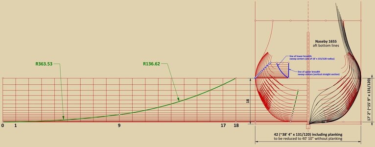
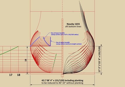
Below is a diagram with the reconstructed design of the aft section (still without the hollowing curves and toptimbers). Quite typical design for the place and period, and using once again a two-part curve (two arcs of the circle) for the rising line of the floor aft, as described by Bushnell 1664.
.
Last edited:
.
Now, for connoisseurs, this may be the best part, but at the same time, for orthodox sceptics clinging to the previous knowledge, it will be a rather uncomfortable discovery.
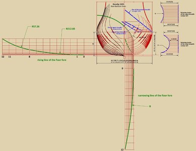
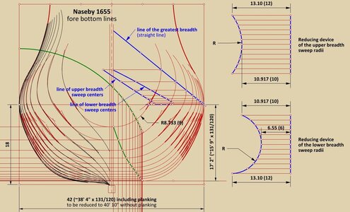
No more and no less, I have just found the second case of application of variable floor sweeps, which historians have hitherto regarded as an invention only from the second half of the 18th century. My first such discovery concerned the London 1656 and, as a reminder, I have also included the relevant diagram below. There are some slight differences in implementation, but the general method is very similar.
Precisely because this is the second finding of its kind, I feel entitled to conclude that variable floor sweeps may have been the standard method of achieving smooth hull surfaces by English shipwrights in the 17th century (or at least some of them). After the adoption in the first decades of the 18th century of waterlines and diagonals fulfilling corrective functions, variable floor sweeps went out of common use but were not forgotten. They experienced their renaissance in the second half of the 18th century, used by some shipwrights with more traditional inclinations, such as John Williams.
The rising line of the floor is again a line constructed from two arcs of a circle of different radii which, especially when three-dimensionally combined with other lines, gave not very harmonious resultant shapes.
In brackets are the supposed values for the ships of the 1654 programme.
Reconstructed lines of the London 1656:
Thanks for watching so far.
Waldemar Gurgul
Now, for connoisseurs, this may be the best part, but at the same time, for orthodox sceptics clinging to the previous knowledge, it will be a rather uncomfortable discovery.
No more and no less, I have just found the second case of application of variable floor sweeps, which historians have hitherto regarded as an invention only from the second half of the 18th century. My first such discovery concerned the London 1656 and, as a reminder, I have also included the relevant diagram below. There are some slight differences in implementation, but the general method is very similar.
Precisely because this is the second finding of its kind, I feel entitled to conclude that variable floor sweeps may have been the standard method of achieving smooth hull surfaces by English shipwrights in the 17th century (or at least some of them). After the adoption in the first decades of the 18th century of waterlines and diagonals fulfilling corrective functions, variable floor sweeps went out of common use but were not forgotten. They experienced their renaissance in the second half of the 18th century, used by some shipwrights with more traditional inclinations, such as John Williams.
The rising line of the floor is again a line constructed from two arcs of a circle of different radii which, especially when three-dimensionally combined with other lines, gave not very harmonious resultant shapes.
In brackets are the supposed values for the ships of the 1654 programme.


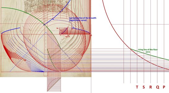
Reconstructed lines of the London 1656:

Waldemar Gurgul
.
Last edited:
.
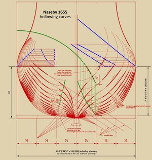
Hollowing curves are invariably one of the most poorly described aspect of ship design in contemporary works. It was either an obvious carpentry skill unworthy of description or, on the contrary, one of the best kept secrets of shipwrights.
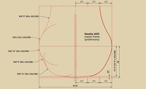
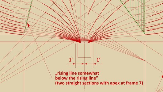
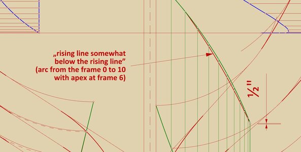
The method shown below has not been described so far (at least for this period) and has been reconstructed from the lines of the scanned model. As the tracing process is already quite complex, it requires an additional description apart from the attached diagram itself:
1. first, temporary floor sweeps were drawn by shifting down the normal floor sweeps by an amount defined by "rising lines somewhat below the rising line" (a term taken from Sutherland 1711),
2. then straight lines tangent to these temporary floor sweeps were drawn radially from more or less arbitrarily chosen points,
3. arcs with a radius of 19.65 (18) feet were later drawn connecting these radial lines to the floor sweeps, and tangentially to these lines,
4. finally, another set of arcs was drawn tangentially to these radial lines and passing through the appropriate points on the keel; the radius of most of these arcs is 10' 11" (10'), at the bow it is 19.65 (18) feet, and there is also an exception at the stern with a radius of 13.1 (12) feet (marked in the diagram).
As can be seen, the process of designing the ship's hull using this 'transverse' design method was a multi-stage task with enough elaboration and finesse to say that it had reached the peak of its capabilities, beyond which there was only a wall. The future belonged to a completely different method, just being born elsewhere, more flexible and at the same time intuitive, based on the harmonious division of the longitudinal design diagonals. This does not mean, of course, that ships designed with different variants of the pulling up/hauling down method had to be always inferior, and those designed on the basis of diagonals were always better, it rather depended on the skills of the designers. Here, it is more about the advantages and qualities of the design methods used.
It may be added that in this particular case, the chosen method of tracing the hollowing curves with its values, effectively lowered the design deadrise by about one inch (taken at 1/3 of the breadth of the ship), and also that just below the design grid is an anomaly of two inches, which may be related to the suspect workmanship of the model in this particular area.
A final remark, that once the method of drawing is found, one can see at a glance all the inaccuracies of the execution of the model and the nature of the minor but quite numerous mistakes the modeller made, alternatively evaluate the model's natural distortion.
.
Last edited:


